SEISMIC DESIGN OF MULTISTORIED AND MULTI BAY STEEL BUILDING FRAME
Chetan Sanjeev Beldar
Department of Civil Engineering
SND College of Engineering & Research Center
Babhulgaon Tal.yeola Dist.Nashik
Prof Nikam PravinAnkushrao
Department of Civil Engineering
SND College of Engineering & Research Center Babhulgaon Tal.yeola Dist.Nashik
Dr S.P.Ahirrao
Department of Civil Engineering
SND College of Engineering & Research Center Babhulgaon Tal.yeola Dist.Nashik ***
Abstract : Steel isone of the world'smost extensivelyused buildingmaterials.Steel isanideal choicefor earthquake designduetoitsinherentstrength,hardness,andductility.Totakeadvantageofthesebenefitsinseismicapplications,the designengineermustbefamiliarwiththerelevantsteeldesignprovisionsaswellasthepurposerepresentedinthecodes. ThebuildingstructureforthisprojectwasdesignedaccordingtoIS1893 2002andIS800.Thepurpose of this studyis to explore and developan earthquake resistantmultistoryand multibay (G+5) building frame using IS 1893 and IS 800:2007. The building stands six floors tall, with three horizontal bays and five lateral bays.Therandompieceselectionwasdoneinasystematicmanner.Theequivalentstaticloadapproachandthe ResponseSpectrummethodwerebothusedintheinvestigation.
INTRODUCTION :-

Seismicanalysisisasubsetofstructuralanalysisthatinvolvesestimatingabuilding'sseismicresponse. In earthquake prone areas, it's part of the structural design, earthquake engineering, or structural evaluation andretrofitprocess.
Themostpowerfulearthquakesstrikeneartheboundariesoftheworld'smajortectonicplates.These plateshaveanaturaltendencytomoverelativetooneanother,butfrictionpreventsthemfromdoingsountil thestressesbetweenplatesundertheepicenterpointgrowsogreatthattheysuddenlyshift.Therehasbeenan earthquake.The localshockcausesgroundwavesto travel throughouttheearth'ssurface, causingmovement atthefoundationsofstructures.Wavesbecomelessimportantasyougetfurtherawayfromthecore.
As a result, depending on their proximity to the main tectonic plate borders, there are regions of the world with a higher or lower seismic risk. Because of their ductility, steel structures are good at resisting earthquakes.Steelstructuresthathavebeensubjectedtoearthquakeshaveshowntoperformwell.Structures composedofdifferentmaterialsaregenerallyassociatedwithglobalcollapsesandlargenumbersofvictims.
Because element failure is not ductile, a structure constructed to the first choice will be heavier and maynotprovideasafetymargintocoverearthquakeactionsthatarehigherthanplanned.Theglobalbehavior of the structure in this scenario is "brittle," which corresponds to concept a) in a Base Shear V Top Displacementdiagram.Inthesecondoption,certainareasofthestructurearebuilttowithstandcyclicplastic deformationswithoutfailure,andthestructureasawholeisdesignedsothatonlythoseselectedzoneswillbe plastically
InternationalResearchJournalofEngineeringandTechnology(IRJET) e ISSN: 2395 0056
Volume: 09 Issue: 05 | May 2022 www.irjet.net p ISSN: 2395 0072
LOAD PARAMETERS:
LoadCalculationThedeadloadissetto=5KN/m2whiletheliveloadissetto3 KN/m2
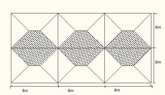
Fig: Load distribution diagram
METHODOLOGY:
The preliminary design of the building frame is the first phase. The technique entails the choosing of sections of frame members. Because the dynamic action effects are a function of member stiffness, a lot of iterationisunavoidable.
Moment resistant frames (MRF) provide earthquake resistance in both the x and y directions in the buildingunderconsiderationhere.MRFs(momentresistantframes)areatypeofflexiblestructure.Asaresult, they are frequently designed to meet deformation standards under service earthquake loading or to limit P effectsunderdesignearthquakeloading.Becauseofthis,stiffconnectionsarepreferable.
Thestepsinthepreliminarydesignareasfollows: 1. BeamSectionsSelection 2. Checkingthe"weakbeamstrongcolumncriteria"whendefiningcolumnsections. 3. Checkforbucklingorcompressionatgroundlevelundergravityloading. 4. Seismicmasscalculation 5. Astaticanalysisofasingleplanestructuresubjectedtolateralloads. 6. Gravityloadingstaticanalysis. 7. Inaseismicloadingsituation,checkforstabilityusingP effects(parameter).
InternationalResearchJournalofEngineeringandTechnology(IRJET) e ISSN: 2395 0056
Volume: 09 Issue: 05 | May 2022 www.irjet.net p ISSN: 2395 0072
1. LATERAL FORCE METHOD:-
Theseismicloadoneachflooriscalculatedatfulldeadloadandimposedload.Anylevel'scolumnand wallweightshouldbeevenlydistributedbetweenfloorsaboveandbelowit.Largepercentagesofserviceload arepredictedtobepresentinbuildingsbuiltforstorageatthetimeoftheearthquake.Theimposedweighton theroofisnottakenintoaccount. The equivalent static technique, which accounts for the dynamics of the buildings in an approximate manner,isusedtocalculatethedesignseismicbaseshear. Thefollowingassumptionsaremadebytheidenticalstaticmethodtechnique. Thefundamentalmodeofconstructioncontributesthemosttobaseshear. Thewholebuildingmassiscomparedtothemodalmassusedinthedynamictechnique,and.Bothofthese assumptionsapplytotypicallowandmedium risestructures.
Table: Analysis by lateral force method
Storeyno. Absolute Displacementof storeyDi (m)
Designinter storeydriftDr(m) Storeylateral forceVtot (KN)
Shearatstorey Ptot(KN) 1 0.003869 0.003869 1.969 179.201 2 0.012595 0.008726 7.951 177.232 3 0.023837 0.011242 17.83 169.281 4 0.035892 0.012055 31.657 151.451 5 0.047566 0.011674 49.212 119.794 6 0.058123 0.010557 70.582 70.582
2. RESPONSE SPECTRUM ANALYSIS: Thisisoneofthemostusedwaystoseismicanalysis.Adesignspectrumdiagramisusedtoachievethis. To idealize a multi story shear structure, the response spectrum technique employs a basic assumption. The mass is gathered at the roof diaphragm and floor levels, according to the assumption. The diaphragms are endlessly stiff, and the column is axially rigid but laterally flexible. The dynamic response of the spectrum is representedaslateraldisplacementsofthelumpedmass,becausethenumberofmassesmatchesthenumber ofdegreesofdynamicfreedom(ormodesofvibrationn).
InternationalResearchJournalofEngineeringandTechnology(IRJET) e ISSN: 2395 0056
Volume: 09 Issue: 05 | May 2022 www.irjet.net p ISSN: 2395 0072
The deflected form is justa mixture of all mode shapes that can be generated by superposition of the vibrations of each individual lumped mass if the ground motion is provided at the base of the multi mass system. The dynamic response of a multi degree of freedom system is determined using a modal analysis approach.Modalanalysis,whichisdetailedinthisarticle,isrecommendedbyIS1893. Eachvibrationmodehasitsownvibrationperiod(anditsuniqueshape,whichisgeneratedbythelocus ofpointsofthedeflectedmasses).
Table: Analysis by response spectrum method.
No. Storey
Absolute displacementof storeyDi (m)
Design inter storeydrift Dr (m)
Storey lateral forceVtot(KN) Shear at storey Ptot (KN)
1
0.00491 0.00491 1.877 120.981 2 0.0115 0.0066 6.112 119.104 3 0.0161 0.0046 10.651 112.992 4 0.0196 0.0035 17.331 102.341 5 0.0219 0.0023 29.98 85.01 6 0.0234 0.0015 55.03 55.03
RESULTS OF LATERAL FORCE METHOD:
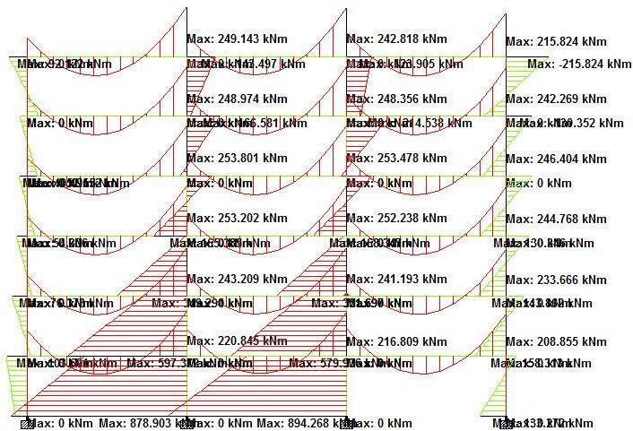
The maximum bending moment, shear force, and other parameters were determined for the load combination1.7(EQ+DL).
FIG Bending moment diagram for load combination 1.7(EQ+DL)
InternationalResearchJournalofEngineeringandTechnology(IRJET) e ISSN: 2395 0056
Volume: 09 Issue: 05 | May 2022 www.irjet.net p ISSN: 2395 0072
RESULTS OF RESPONSE SPECTRUM ANALYSIS:
The maximum bending moment, shear force, and other parameters are calculated for the load combination1.3(DL+LL+EQ).
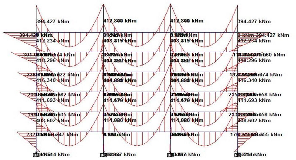
Fig (6.3) Bending moment diagram for load combination 1.3(DL+LL+EQ)
CONCLUSION:
1. Inter storeydriftwasdeterminedusingthelateralforcemethodandtheresponsespectrummethod,with theresponsespectrummethodyieldingsmallerdisplacementsthanthelateralforcemethod.
2. TheresponsespectrummethodfindslessStoreyshearthanthelateralforcemethod.
3. The lateral force method's assumptions are to blame for the disparity in results between the response spectrumandlateralforcemethods.Theyare:
4. a. Thefundamentalmodeoftheconstructionhasthemostimpactonthebaseshear.
5. b. Thetotalmassofthebuildingiscomparedtothemodalmassemployedinthedynamicmethod.Both assumptions arecorrectfornormallowandmediumrisebuildings.
6. Asseenintheabovedata,thevaluesobtainedbydynamicanalysisarelowerthanthoseproducedthrough the lateral force approach. This is because the dynamic analysis initial mode period of 0.62803 is longer thantheprojected0.33softhelateralforceapproach.
7. The first modal mass accounts for 85.33 percent of overall seismic mass, according to the research. The timeperiodis0.19s,andthesecondmodalmassis8.13percentoftheoverallseismicmassm.
InternationalResearchJournalofEngineeringandTechnology(IRJET) e ISSN: 2395 0056
REFERENCES:-
N.Subramanian,OxfordUniversityPress,DesignofSteelStructures,7thedition,2011,173 209.
LSNegi,TataMc GrawHillPublishingCompanyLimited,DesignofSteelStructures,2ndedition,1997
Earthquake Resistant Design of Structures, PankajAgarwal and Manish Shrikhande, Prentice Hall of India Limited,July2006,251 336.
AnExampleofArcelor MittalDesign(www.arcelor mittal.org)
GeneralConstructioninSteel CodeofPractice,IS800:2007,ThirdRevision
Criteria for Earthquake Resistant Design of Structures, Part 1 General Provisions and Buildings, IS 1893:2002,FifthRevision.
Volume: 09 Issue: 05 | May 2022 www.irjet.net p ISSN: 2395 0072 © 2022, IRJET | Impact Factor value: 7.529 | ISO 9001:2008 Certified Journal | Page3806