International Research Journal of Engineering and Technology (IRJET) e ISSN: 2395 0056

Volume: 09 Issue: 05 | May 2022 www.irjet.net p-ISSN: 2395-0072
International Research Journal of Engineering and Technology (IRJET) e ISSN: 2395 0056
Volume: 09 Issue: 05 | May 2022 www.irjet.net p-ISSN: 2395-0072
Rohit Sunil Navale Department of Civil Engineering
SND College of Engineering & Research Center Babhulgaon Tal.yeola Dist.Nashik
Prof. Nikam Pravin Ankushrao Department of Civil Engineering
SND College of Engineering & Research Center Babhulgaon Tal.yeola Dist.Nashik
Dr Mate N.U. Department of Civil Engineering
Amrutvahini College of Engineering, Sangamner, Dist.Ahehmadnagar ***
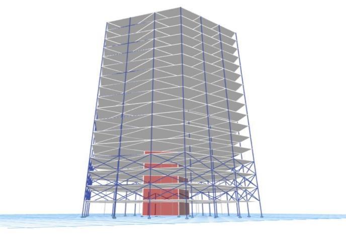
Abstract Theincreasingrequirementtoachievelargerheightshasfueledthegrowthofstructuralsystemconceptsfor tallbuildings.Structuralengineershavebeenabletodesignandconstructbuildingsthathavegrownhigherandhigherfor overa century.Manynewideashavearisenasa resultofthisprocess,includingtherelativelynewandground breaking high rise diagrid structural system. The diagrid structure was born from the development of this notion to a system without vertical columns. For tall buildings, digrid structural systems are developing as structurally efficient and architecturally remarkable assemblies. Diagrid structures are effective in terms of both strength and stiffness in giving solutions.A tall skyscraper with a G+16 storey structure is investigated and compared under various circumstances. We explore three modules in our project: structures without diagonal grids, structures with diagonal grids at selected bay's outerface,andstructureswithdiagonalgridsatselectedbay'sinnerface.Storeydriftsanddisplacementwillbecompared, aswellasaxialforcesandbendingmoments,andshearforcesinthecolumn.
Keywords: Displacement,StoryDrift,BendingMoment,AxialForces,ShearForces,
INTRODUCTION: Thediagridisatypeofdiagonalmemberthatisusedinbothgravityandlateralloadresisting systems.Bracedtubestructureshaveevolvedintodiagridsystems.Engineerscannowusecutting edgestructuralsystems toconstructstructuresthataremorethan100storiestall.Researchersbeganusingthetermdiagrid,whichisamixof diagonalandgrid,in1970.Diagridisasteel frameconstructionmethodthatresultsintriangularstructureswithdiagonal supportbeams.Asidefromeliminatingperimetercolumns,thediagriddesignhasotheradvantages.Verticalloadcarrying capabilityisoftenprovidedbycolumns,withdiagonalsorbracesprovidingstabilityandresistancetolargeforceslikeas windandseismicstresses.Thediagrid'sdiagonalmembercarriesbothshearandmoment.Asaresult,thebestanglefor placingdiagonalsisdeterminedbytheheightofthebuilding.
International Research Journal of Engineering and Technology (IRJET) e ISSN: 2395 0056
Volume: 09 Issue: 05 | May 2022 www.irjet.net p-ISSN: 2395-0072
• "Diagrid: An innovative, sustainable, and efficient structural system," by Esmaeel Asadi and Hojjat Adeli, published in 2016.
This study discusses several diagrid configurations, as well as the primary aspects that influence their behaviour and designparameters.Thediagridapplicationsforfreeformsteelandconcretestructuresarepresented,demonstratingthe diagrid's applicabilityinstructural designforcomplicatedbuildings.Italsocovers diagridconnections, nonlineardiagrid behaviour,anddiagridstructuralcontrol.Thearticlesuggeststhatdiagridhasthepotentialtobecomeamoreextensively employedstructuralsysteminmidtohighrisebuildingsduetoitsexceptionallateralstiffnessandaestheticqualities.The adjustability of diagrid density and diagonal angle, as well as the flexibility of triangulated diagrid parts to produce complexforms,aretheessentialstructuralpropertiesofdiagrids.
• "Improving the seismic performance of diagrid buildings with buckling constrained braces," Saman Sadeghi and Fayaz R. Rofooei, 2019.
The seismic performance of diagrids with buckling limited bracing is investigated in this study (BRBs). The seismic performance factors of six three dimensional diagrid structures with varied heights and diagonal angles that were modelled using the Open sees programme are evaluated using nonlinear static analysis. The findings show that utilising BRBs enhances the seismic performance of the models investigated by collecting plastic damages in the BRBs and spreadingplastichingesmoreuniformlyacrossthemodels.
• "Seismic fragility evaluation of a diagrid structure based on energy approach," Majid Moradi and Moein Abdolmohammadi (2020).
The goal of this research is to use energy approach principles to analyse the seismic behaviour of diagrid structural systems under near field and far field earthquakes in order to acquire a better understanding of their seismic behaviour and the benefits of adopting energy approaches. The Incremental Dynamic Analysis (IDA) method and a finite element model are used to investigate the behaviour of a 50 story skyscraper. The results reveal that the structure is more vulnerable in far field earthquakes than in near field earthquakes, using both the maximum story drift and energy approaches.
Thefollowingisthemethodsusedtoattaintheaforementionedgoals: i) Conductaliteraturereview ii) InETABSoftware,chooseabuildingmodelforthestudy. iii)Createadiagonalcolumnmodelofthechosenstructure(diagridbracing).
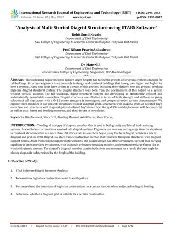
Model1:Plainhexagonalstructurewithnobracing.
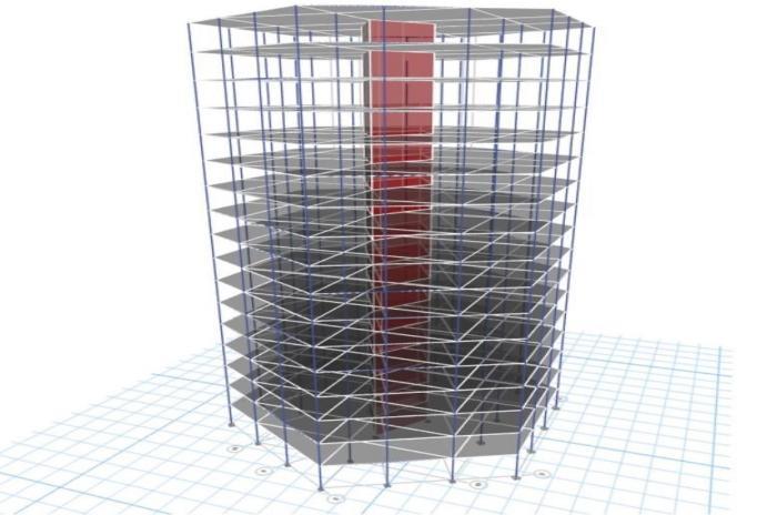
Model2:Astructurefeaturingdiagonalbracing(diagrids)ontheground,first,andsecondfloors.
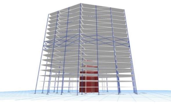
Model3:Astructurehavingdiagonalbracingonthe13th,14th,and15thfloors.
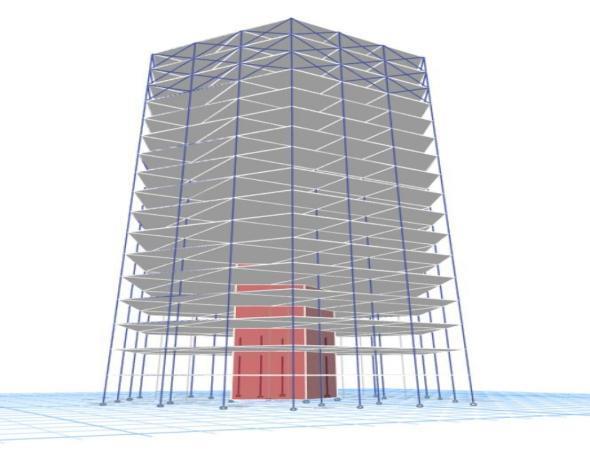
Model4:Astructurefeaturingcrossbracingonthe7thand8thfloors.
iv) AcomparisonassessmentofthedataproducedfromtheanalysisinETABSoftwareandaseismicanalysisofthe selected buildingmodel.
v) Discussionsandobservationsofoutcomes
International Research Journal of Engineering and Technology (IRJET) e ISSN: 2395 0056
Volume: 09 Issue: 05 | May 2022 www.irjet.net p-ISSN: 2395-0072
Theloadpatternappliedonthestructuresisasfollows:
Define Load Pattern Type of Load Load DeadLoad(DL) Dead LiveLoad(LL) Live 2kN/m FloorFurnishLoad SuperDead 1.5kN/m WallLoad SuperDead 10kN/m EarthquakeLoadinx dir (EQX) Seismic SeismicZoneFactorZ 0.16 ImportanceFactorI 1.2 EarthquakeLoadiny dir (EQY) Seismic SeismicZoneFactorZ 0.16 ImportanceFactorI 1.2
BasicLoadCombinationsasper[IS456:2000,Table18,pg.no.68].
1. 1.5(DL+LL) 14.1.2(DL+LL+EQX)
2. 1.2(DL+LL+WLX) 15.1.2(DL+LL+EQ X)
3. 1.2(DL+LL+WL X) 16.1.2(DL+LL+EQY)
4. 1.2(DL+LL+WLY) 17.1.2(DL+LL+EQ Y)
5. 1.2(DL+LL+WL Y) 18.1.5(DL+EQX)
6. 1.5(DL+WLX) 19.1.5(DL+EQ X)
7. 1.5(DL+WL X) 20.1.5(DL+EQY)
8. 1.5(DL+WLY) 21.1.5(DL+EQY Y)
9. 1.5(DL+WLY Y) 22.0.9DL+1.5EQX 10. 0.9DL+1.5WLX 23.0.9DL+1.5EQ X 11. 0.9DL+1.5WL X 24.0.9DL+1.5EQY
12. 0.9DL+1.5WLY 25.0.9DL+1.5EQ Y 13. 0.9DL+1.5WL Y
14. Various load combinations as per [IS 1893 part 1:2016, 6.3.2.2, pg. no. 8] have been implemented on the structure. Theyareasfollows:
15. 1.2DL+1.2LL+1.2EQX+0.36EQY
16. 1.2DL+1.2LL 1.2EQX 0.36EQY
17. 1.2DL+1.2LL+1.2EQY+0.36EQX
18. 1.2DL+1.2LL 1.2EQY 0.36EQX
19. 1.5DL+1.5EQX+0.45EQY
20. 1.5DL 1.5EQX 0.45EQY
21. 1.5DL+1.5EQY+0.45EQX
22. 1.5DL 1.5EQY 0.45EQX
23. 0.9DL+1.5EQX+0.45EQY
24. 0.9DL 1.5EQX 0.45EQY
25. 0.9DL+1.5EQY+0.45EQX 12 0.9DL 1.5EQY 0.45EQX
Model 2: Building with diagonal bracing(diagrids) at Ground floor, 1st floor and 2nd floor.
Item Storey Size Grade of Concrete
Diagrid Ongroundfloor,1st and 2nd floor 230X230mm M30
Model 3: Building with diagonal bracing at 13th storey, 14th floor and 15th floor.
Item Floor Size Grade of Concrete
Diagrid On13th,14th and 15th floor 230X230mm M30
2022, IRJET | Impact Factor value: 7.529 | ISO 9001:2008 Certified Journal | Page3705
International Research Journal of Engineering and Technology (IRJET) e ISSN: 2395 0056
Model 4: Building with cross bracing at 7th floor and 8th floor.
Item Storey Size Grade of Concrete Diagrid
On7th and8th floor 230X230mm M30
Conclusion and Discussion:
Model 1: Plain hexagonal structure with no bracing.
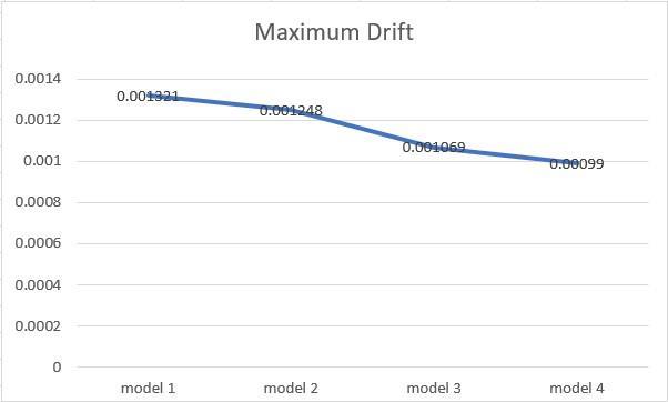
A hexagonal building with G+16 stories and no diagrid is considered. The greatest drift found after the analysis was 0.001321. Under the operation of the design base of shear, storey drift in any storey shall not exceed 0.004 times the storey height [IS 1893 part1:2016]. As a result, the structure is not safe since it shows more deflection than is required, namely0.0012.
Model 2: A structure featuring diagonal bracing (diagrids) on the ground, first, and second floors.
A 16 story hexagonal building with diagrids on the ground, first, and second floors is considered. The largest drift found aftertheanalysiswas0.001248.Asaresult,thestructureissafebecauseithasthesamedeflectionastherequired0.0012.
Model 3: A structure having diagonal bracing on the 13th, 14th, and 15th floors.
A16 storyhexagonalskyscraperfeaturingdiagridsonthe13th,14th,and15thfloorsisbeingconsidered.Thelargestdrift foundaftertheanalysiswas0.001069.Asaresult,thestructureissafebecauseithaslessdeflectionthanrequired,namely 0.0012.
Model 4: A structure featuring cross bracing on the 7th and 8th floors.
A16 storyhexagonalstructurefeaturingdiagridsonthe7thand8thfloorsisbeingstudied.The greatestdriftfoundafter theanalysiswas0.00099.Asaresult,thestructureissafebecauseithaslessdeflectionthanrequired,namely0.0012.
Graph1.Maximumdriftofthefourmodels.
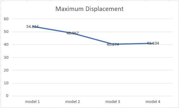
Graph2.Maximumdisplacementofthefourmodels.
1. AccordingtoIS1893part 12016,thelateraldisplacementofhexagonalbuildingsisgreaterthanenvisaged.
2. It was discovered that the maximum drift was correct to the required drift according to IS code after installing diagonalbracings(Diagrid)attheground1stand2ndfloors.
3. After installing diagonal bracings (Diagrid) on the 13th, 14th, and 15th floors, it was discovered that the maximum
Volume: 09 Issue: 05 | May 2022 www.irjet.net p-ISSN: 2395-0072 © 2022, IRJET | Impact Factor value: 7.529 | ISO 9001:2008 Certified Journal | Page3706
International Research Journal of Engineering and Technology (IRJET) e ISSN: 2395 0056
driftwaslessthantheIScode mandateddrift.
4. Afterinstallingdiagonalbracings(Diagrid)onthe7thand8thfloors,itwasdiscoveredthatthemaximumdriftwasfar lessthantheIScoderequireddrift.
5. As a result, the building's drift when diagrids are installed at the bottom storeys is greater than the building's drift whendiagridsarepositionedatthetopstoreys.Also,whenthediagridsareputinthestructure'smiddlestories,the driftisreducedtoaminimum.
6. Whencomparingthefourmodelsofeachcolumn,thereisnosuchvarianceinaxialforceandshearforce.
7. Thebendingmomentsofthemodelsdifferslightly.
1.EsmaeelAsadiandHojjatAdeli,Wiley,Dec2016,"Diagrid:Aninnovative,sustainable,andefficientstructure system."
2. Saman Sadeghi, Fayaz R. Rofooei, “Improving the seismic performance of diagrid structures using buckling restrained braces.”,JournalofConstructionalSteelResearch166,2019.
3."Seismic fragility assessment of a diagrid structure using the energy technique," Majid Moradi and Moein Abdolmohammadi,JournalofConstructionalSteelResearch174,2020.
4. Vahid Mohsenian, Saman Padashpour, Iman Hajirasouliha, “Seismic reliability analysis and estimation of multilevel responsemodificationfactorforsteeldiagridstructuralsystems.”,JournalofBuildingEngineering,2019.
5. G.B. Ramesh Kumar and Neha Tirkey, "Analysis on the diagrid structure with the Conventional building frame using ETABS," Materials Today: Proceedings, Elsevier, 2019."Analyzing alternative configurations of variable angle diagrid structures." by Kamil Ashraf Bhat and Peerzada Danish, Elsevier, Materials Today: Proceedings,2020
Volume: 09 Issue: 05 | May 2022 www.irjet.net p-ISSN: 2395-0072 © 2022, IRJET | Impact Factor value: 7.529 | ISO 9001:2008 Certified Journal | Page3707