International Research Journal of Engineering and Technology (IRJET) e ISSN: 2395 0056

Volume: 09 Issue: 05 | May 2022 www.irjet.net p ISSN: 2395 0072
International Research Journal of Engineering and Technology (IRJET) e ISSN: 2395 0056
Volume: 09 Issue: 05 | May 2022 www.irjet.net p ISSN: 2395 0072
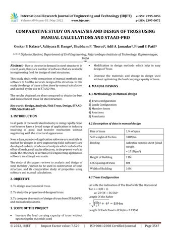
Omkar S. Kalase1, Adityara B. Dange2, Shubham P. Thorat3 , Adil A. Jamadar4, Pranil S. Patil5
1,2,3,4,5 Diploma Student, Department of Civil Engineering, Rajarambapu Institute of Technology, Rajaramnagar, India ***
Abstract - Duetotheriseindemandinsteelstructuresin recentyears,therearenumberofsoftwarethatareavailable inengineeringfieldfordesignofsteelstructures.
Thisstudydealswithcomparisonofmanual methodsand softwaretofindtheaccuratedesignofthestructure.Inthis studythedesignoftrussisfirstdonebymanualcalculation andsecondbytheuseofSTAAD Pro.
Theresultsobtainedarethencomparedtoobtainthebest andmostefficienttrussforsteelstructure.
Key words: Design, Analysis, Fink Truss, Design, STAAD PRO, Steel take off
Inallpartsoftheworldsteelindustryisrisingrapidly.Steel roof trusses have a broad range of application in industry involving of good load transfer mechanism without negotiatingwiththestructuralappearance.
Nowadays,numberofapplicationsoftwareareavailablein marketfordesignsincivilengineeringfield.software’sare developedonbasisofadvancedanalysiswhichincludesthe effectofloads,earthquakeeffectsetc.inthepresentwork,to studytheefficiencyofcertaincivilengineeringapplication softwareanattemptwasmade.
The study of this paper reviews to analysis and design of steel member /section to be used in construction of steel structure, and its comparative study of properties using softwareandmanualcalculations
1.Todesignaneconomicaltruss. 2.Tostudythepropertiesofdesignedtruss.
3.TocomparetheresultsofdesignoftrussfromSTAADPRO andmanualcalculations.
Increase the load carrying capacity of truss without optimizingthematerialsused
Modification in design methods which help in easy designofTruss
Decrease the materials and change in design used withoutoptimizingtheloadcarryingcapacityoftruss.
4. MANUAL DESIGNS
4.1 Methodology in Manual design 1]Trussconfiguration 2]LoadsConfiguration 3]Memberforces 4]Reactions 5]Resultants
4.2 Description of data in manual design
Riseoftruss 1/4ofspan
Self weightofPurlins 318N/m
Roofing
Asbestoscementsheet(dead weight =171N/m2)
HeightofBuilding 11M
C/CSpacingoftruss 8M
WidthofBuilding 16M
4.3 Truss Configuration
LetɑBetheInclinationofTheRoofwithTheHorizontal Tanɑ=4/8=½ ɑ=26o34’ =26.566o
LengthOftheRafter =
LengthOfEachPanel=8.94/4=2.235M
International Research Journal of Engineering and Technology (IRJET) e ISSN: 2395 0056
Volume: 09 Issue: 05 | May 2022 www.irjet.net p ISSN: 2395 0072
=6700/2=3350N=3.35KN

AssumeWeightofBracing=12N/M2 DeadWeightofAcSheetSheets=171N/M2 Self WeightofPurlin=318N/M2 =318x8=2544N
PanelLength=2.235m
ThePanelLengthinPlan =2.235Cos260 34’=2.00m.
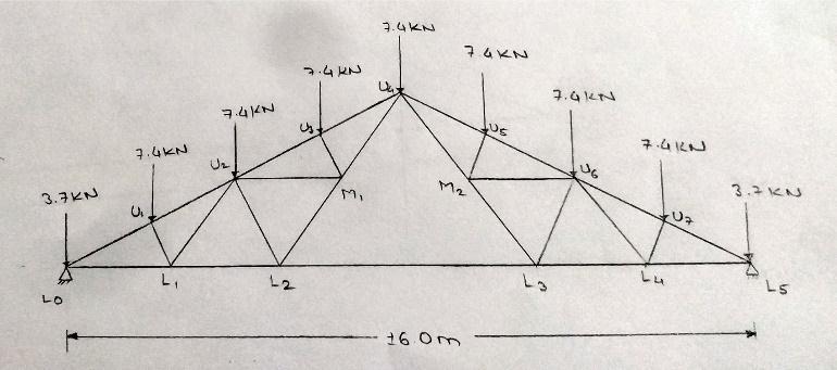
LoadOnEachIntermediatePanelDuetoDeadLoad =(12+171+110)X(8X2)+2544=7232N ≌7.4KN
LoadOnEndPanelPointsoftheRafter =7.4/2=3.7KN
ɑ=26o 34’=26.566o
AssumeNoAccessProvidedtoTheRoof.TheLiveLoadIs ReducedBy20N/M2
ForEachOneDegreeAbove10o Slope LiveLoad=750 20X(26.566 10) =418.68N/M2
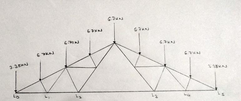
TheLoadOnEachIntermediatePanel =418.68*8*2 =6698.88N=6700N=6.7KN
TheLoadOnEachPanelPoint
ExpectedTheLifeoftheIndustrialBuildingis50Years andTheLandisPlainandSurroundedbynumberSmall Building
K1 = 1.0
K2 = 0.89
K3 = 1.0 Vb = 47 M/S
Design Wind Speed Vz =K1 *K2 *K3 *Vb = 1.0*0.89*1.0*47
Design Wind Pressure, Pd = Vz 2 =0.6*41.832=1049.8N/M2
HeightOfBuildingColumnAboveGroundLevel,H=11m
WidthOfBuilding,W=16m
InThisPresentExampletheRoofAngleΑIs26.566oFor WhichtheCoefficientsAreTabulatedBelow
TheValuesofCoefficientCpeforVariousConditionsinThe TableHaveBeenCalculatedbyTheInterpolationfor AppendixXvIs800 PartIII
1) Windward Side
F1 = = ( 0.8 0.2) X 1.05 X (8 X 2.235) = 18.77≌ 18.8kn
2022, IRJET | Impact Factor value: 7.529 | ISO 9001:2008 Certified
International Research Journal of Engineering and Technology (IRJET) e ISSN: 2395 0056
Volume: 09 Issue: 05 | May 2022 www.irjet.net p ISSN: 2395 0072
F2 = 18.8/2 = 9.4 KN [ Intermediate Panel Points]
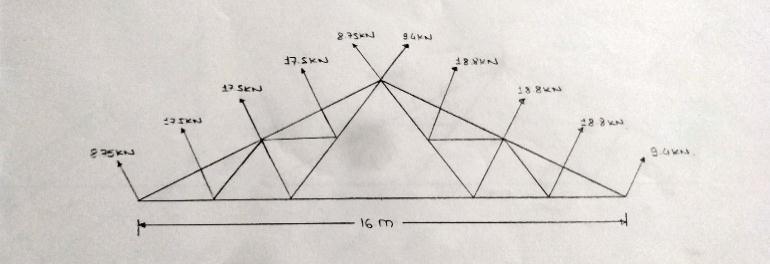
2) Leeward Side
F3 = = ( 0.731 0.2) X 1.05 X (8 X 2.235) = 17.48≌ 17.5kn
F4 = 17.5/2= 8.75 KN [Intermediate Panel Points]
Horizontalcomponent = 75.2sin 26.566o = 33.63 KN →
Nethorizontalcomponent = 33.63 31.30 = 2.33kN →
Horizontalforceateachfaceshoe = 2.33/2 = 1.165kN →
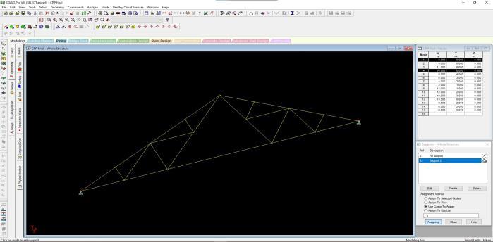
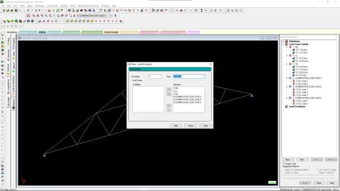
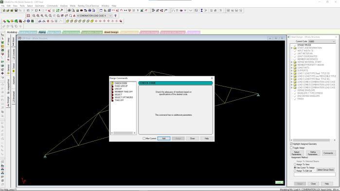
MethodologyusedindesignonSTAAD
1]Snapnode/beam
2]Supports
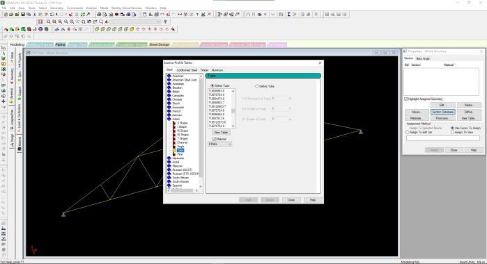
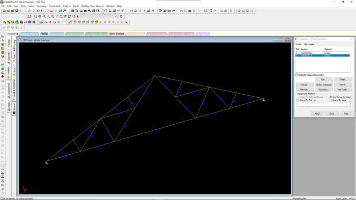
3]Properties
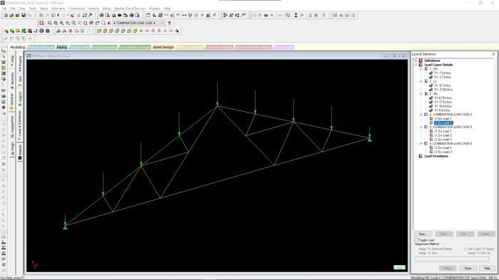
4]Loading[DL,LL,WL]
5]LoadEnvelope
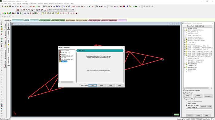
6]SteelDesign ApplyIScodes
Thetrussissymmetricalandtherefore,thedeadloadand live reactions will be the same on both supports but the reactions due to wind load will be different on the two supports
Dead Load Reaction
Taking Moment at Lo 7.4 X 2 + 7.4 X 4 +7.4 X 6 + 7.4 X 8 + 7.4 X 10 + 7.4 X 12+ 7.4 X 14 + 3.7 X 16 = R15 X 16
Rl0 = 29.6KN
By Symmetry, Rl0 = Rl5= 29.6KN
Taking Moment at L0 6.7 X 2 + 6.7 X 4 +6.7 X 6 + 6.7 X 8 + 6.7 X 10 + 6.7 X 12+ 6.7 X 14 + 3.35 X 16 = R15 X 16
Rl0 = 29.6kn
By Symmetry, Rl0 = Rl5= 29.6 KN
Force: 70.0 KN
Verticalcomponent = 70.0 cos 26.566o =62.60kN ↑
Horizontalcomponent = 70.0 sin 26.566o =31.30 KN ←
Force:75.2kN
Verticalcomponent = 75.2 cos 26.566o = 67.26 KN ↑
7]SteelTake off 8]Analysisofloads
9]Results
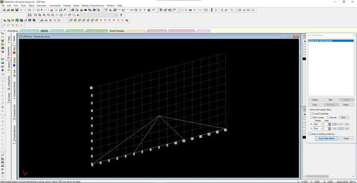
STAADDesign:
Use of figures has been done to explain the design process
Figno5AssigningNode/beam
FigNo.6AssigningSupports
© 2022, IRJET | Impact Factor value: 7.529 | ISO 9001:2008 Certified Journal |


International Research Journal of Engineering and Technology (IRJET) e ISSN: 2395 0056 Volume: 09 Issue: 05 | May 2022 www.irjet.net p ISSN: 2395 0072


International Research Journal of Engineering and Technology (IRJET) e ISSN: 2395 0056


Volume: 09 Issue: 05 | May 2022 www.irjet.net p ISSN: 2395 0072
International Research Journal of Engineering and Technology (IRJET) e ISSN: 2395 0056
Volume: 09 Issue: 05 | May 2022 www.irjet.net p ISSN: 2395 0072
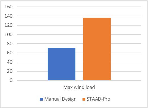
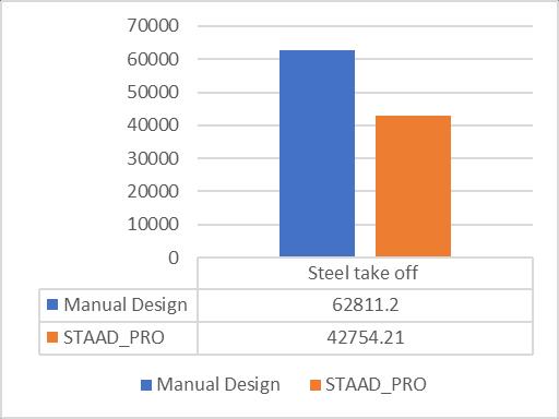
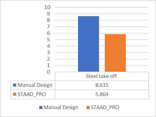
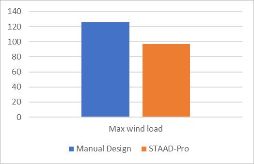
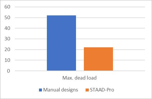
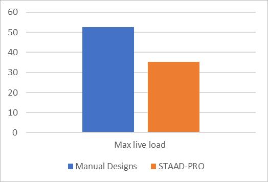
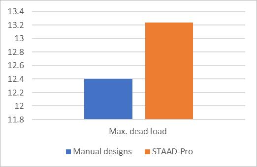
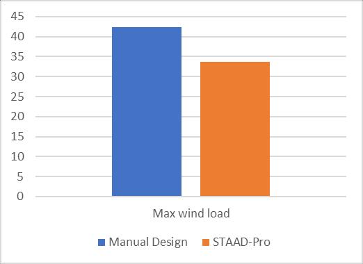
1. Fromtheaboveresultsweconcludethattheaxial forcesinMANUALDESIGNaremoreascomparedto STAAD PRO.
2. From the above results we conclude that the STAAD PROismoreeconomictouseaslessforces arerequired.
3. From the above results we conclude that STAAD PRO model is more economical and suitable for buildingaslessmaterialarerequiredascanresista greaternumberofforcesthanmanualdesign