1
International Research Journal of Engineering and Technology (IRJET) e ISSN:2395 0056

Volume: 09 Issue: 04 | Apr 2022 www.irjet.net p ISSN:2395 0072

1
International Research Journal of Engineering and Technology (IRJET) e ISSN:2395 0056
Volume: 09 Issue: 04 | Apr 2022 www.irjet.net p ISSN:2395 0072
1Faculty of Electrical DepartmentYCCE, Nagpur Nagpur, India 2,3,4,5 Student of Electrical Department, Final YearYCCE, Nagpur, India. ***
Abstract
Nowadays, use of conventional vehicles is increasing rapidly, which cause to rise pollution and dangerous
environmental effects. Hence, Electric vehicle comes into a picture, because they runs on no or very less fuel. This vehicle totally runs on battery, so battery charger system should be fast and work effectively. So, here in our paper we have use boost converter to charge our battery. Along with this we have also used rectifier circuit, CT, PT, micro controller. We used boost converter because it is chip and boost output voltage that’s why efficiency of battery charger increases. Here, we try to maintain power factor at AC side near to unity that’s why losses in system decreases and ultimately efficiency increases. Simulation in the paper shows the practical output of our topic, which is nearly unity and output waveform is almost ripple free. So, we get almost DC wave for battery charging.
Keywords Electric vehicles (EV), Proportional Integral Derivative (PID), Metal Oxide Semiconductor Field Effect Transistor (MOSFET, Boost converter, Comparator, Power Factor Correction (PFC).
Emerging trends in vehicles nowadays have created huge progress in a field of automobiles, but rapid increase in a numberofconventionalvehiclesleadstoincreaseinpollutionandalsouseoffuel.Thisbothfactorshaveveryharmfuland dangerous effect economy as well health too. So to overcome all these challenges there is a invention of Electric Battery vehicle. Electric vehicle includes Electric lorries, electric trains, electric cars, Electric trucks. Battery is virtual soul or heartofEV. Thedesignofthebattery should besuch thatitshouldabletocharge itselffastandWork efficiently E Vhas zero fuel emission. EV works on very less or no fuel, so it is a green energy. EV runs on battery so the battery needs to chargedaily.Henceweneedefficientaswallasfastbatterycharger.Hencethistopiccomesintoapicture.
Here transformer to step down the voltage of 230v to 12v. We have use rectifier to convert AC DC as battery needs DC supply.Capacitorsarealsousedhereasafiltertoremovethedistortions ina signal. Anddue tothisEVbatterychargers haveveryhigh efficiency.Herewehave useda Boostconverter becauseitisthecost effectiveand most reliablesolution forbothinputcurrentshapingcapabilityandvoltageregulation.BoostconverterisDC DCtypeofconverter.
Whichisusedtostepupthevoltageattheoutputside.
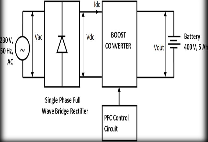
TheBlockdiagramfortheproposedworkisshowninthebelowfigure(3)thisprojectconsistsofthreemaincircuitsthose circuitsare:
Prof. Atul Lilhare sir, 2Achal Shravanji Ekunkar, 3Rutuja Ratnakar Tambekar, 4Shivani Ramesh Kalmore, 5Aishwarya Ramdas KhandteInternational Research Journal of Engineering and Technology (IRJET) e ISSN:2395 0056
Volume: 09 Issue: 04 | Apr 2022 www.irjet.net p ISSN:2395 0072
AsshownintheBlockDiagramthe230VoltACSupplyisgiventotheBridgeRectifier.TheBridgeRectifierisSingle phase FullWaveBridgeRectifierasitistermedanUncontrolledrectifierinthattheappliedinputvoltageispasseddirectlytothe outputterminalsprovidingafixedaverageDC207.06Volt.TheOutputoftheRectifierisgiventotheBoostConverter.The output voltage of the bridge rectifier is connected to the Inductor the rating of the inductor is 0.3mH. The solid state devicewhichoperatesasaswitchisconnectedacrossthe bridgerectifierwhichisMOSFET.ThegatepulseofMOSFETis givenbythePFCControlCircuitwhichisusedforimprovingthepowerfactoroftheCircuitandtoimprove theefficiency ofthecircuit.Thediodeisconnectedtoa capacitor;theratingofthecapacitoris2000microfarad whichisusedtoripple by smoothing capacitors that convert the ripple voltage into a smoother dc voltage. As aLoad, the battery is used. The ratingoftheBatteryis400 VoltandtheStateofChargeofthebatteryiskeptat30,sothebatterygetschargedupto400 Volt.
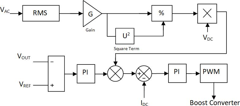
WeneedtodetectpeakvalueofACinputvoltageinordertogeneratesinusoidalreferenceforthecurrentcontroller.Then we have voltage regulator to control voltage which isfollowed by the current controller. It controls inductorcurrent and also maintains sinusoidal wave shape and finally the output is given to the PWM block which is connected to the gate terminaloftheMOSFET
Output of Simulation of Input Supply:
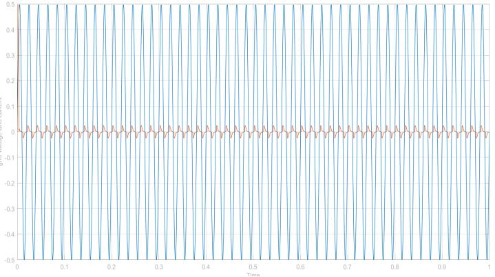
Fig.3:InputACSupplyVoltageandCurrent
2022, IRJET | Impact Factor value: 7.529 | ISO 9001:2008
International Research Journal of Engineering and Technology (IRJET) e ISSN:2395 0056
Volume: 09 Issue: 04 | Apr 2022 www.irjet.net p ISSN:2395 0072
AsshowninFig.3ItistheSimulatedWaveformofInputsideVoltageandcurrentwhichisACWaveform.TheRMSvalueof Voltageis230Volts,itspeakvalueis325.26VoltsandtheCurrentis0.03AmpereastheBatteryisfullycharged.
Output of Simulation of Bridge Rectifier:
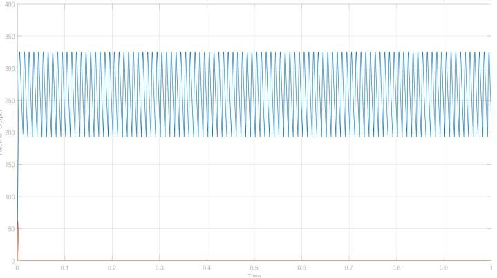
Fig.4:OutputVoltageandCurrentWaveformofBridgeRectifier
Output Current Waveform of Bridge Rectifier As shown in the Waveform, It is the Simulated Output Waveform of the BridgeRectifierwhichis DCVoltageandDcCurrent.TheaverageoutputvoltageoftheBridgeRectifieris207.06Volts,and theaveragecurrentis0.002ampere.
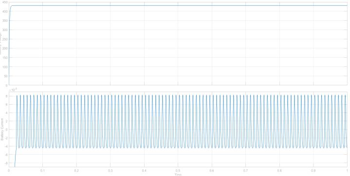
Output of Simulation of Battery:
AsshownintheWaveform,Itisthesimulatedoutput WaveformofChargingoftheBattery,The BatterygetsChargedup to430VoltastheStateofChargeoftheBatteryis50%andthecurrentisupto0.008Ampere.
When the angle between Current and Voltage comes near to the unity then It is called an improved power factor, In the tapping of the Boost Converter, the gate pulse is taken fromtheclosed loopastheFeedbackistakenfromtheOutput.In theFeedbackcircuit,thelogicisdesignedinsuchawaythat theswitchingoperationofMOSFETisdoneatZerocrossing meanscurrentandVoltageisremaininginphaseandthenthepowerfactorgetimprovedinBatteryastheLoadisBattery.
Calculation of parameters:=
InputVoltage(RMS)=230VoltsVmax =VRMS*√2 =325.26Volts © 2022, IRJET | Impact Factor value: 7.529 | ISO 9001:2008 Certified Journal | Page3525
International Research Journal of Engineering and Technology (IRJET) e ISSN:2395 0056
Volume: 09 Issue: 04 | Apr 2022 www.irjet.net p ISSN:2395 0072
Rectifier Calculation:
Vdc =2Vm/π
=2*325.26/π
=207.06Volts
Calculation Of DC DC Converter
Lithium ion Battery(Vout)=400VoltsVdc (Vin)=207.06Volts
DutyCycleRatio(D)=1 Vin/Vout =1 207.06/400 =0.5
Capacitor=2000µF
Inductor=0.3mH
Advantages of Power Factor Correction Device:
1) ImprovesPowerFactor.
2) Improvesefficiency.
3) Batterygetchargedatratedvoltage.
CONCLUSION:
Asweassumethatourbatteryvoltagemustreachupto400volts,butwhenweperformedoursimulationweobservethat themaximumreachofbatteryis430volts.As wegivetheInputSupplyas230VoltsAC,ItgetconvertedintoDCbyusing Bridge Rectifier and the average value of Rectifier is 207.06 Volt DC so it get Step up to 400 Volts by using Boost Converter,sowegottheresultsasperourexpectations.
The expected outcome of this paper is to improve the power factor of the Electric Vehicle Battery by using the Zero CrossingDetectiontechniqueastheFeedbackistakenfromtheoutputinaclosedloopandswitchingtheMOSFETatzero crossingthustheanglebetweenthecurrentandvoltagewaveformreducesandpowerfactorcomesneartounityandthe voltageisalsoboostedbyusingboostconverter,Therippleisreducedbyusingthesmoothingcapacitorwhichtransforms theripplevoltageintosmoothingDCvoltage.ThusoverallefficiencyoftheBatteryisimprovedandtheperformanceofthe batteryalsogetsimproved
We would like to express our sincere gratitude to our mentor and guide MR. Atul Lilhare sir, Electric Department, Yeshwantrao Chavan college of Engineering, Nagpur, Maharashtra, For his time to time guidance and mentorship. He was always there for us to support, keen interest and promptsupport.Histimelyadvice,meticulousscrutiny,scholarlyadvice,andscientificapproachhavehelpedmetoa very greatextenttoaccomplishthistask.
We owe a deep sense of gratitude to Dr. S. G. KADWANE, Head of Electrical Department (HOD), Yeshwantrao Chavan College of Engineering, Nagpur, for his keen interest in us at every stage of our project. His prompt inspirations, timely. suggestionswithkindness,enthusiasm,anddynamismhaveenabledustocompleteourthesis.Wethankprofuselyallthe staffoftheElectricalDepartment,YeshwantraoChavanCollegeofEngineering,Nagpurfortheirkindhelpandcooperation throughoutourwork.Also,thankstoourallcolleaguesfortheirsupportandwillingnesstohelpoutduringvariousstages of my project. We are so greatful to our family and our friends for their kind help, financial help, and coordination throughoutourstudyperiod.
International Research Journal of Engineering and Technology (IRJET) e ISSN:2395 0056
Volume: 09 Issue: 04 | Apr 2022 www.irjet.net p ISSN:2395 0072
:
[1] V.BharathKumarandM.R.Sindhu,"EVChargerPower
qualityImprovementusingSynchronousrectifiedBridgeless CUKConverter,"2021IEEEInternationalPowerandRenewableEnergyConference(IPRECON),2021, pp. 1-6, doi:
10.1109/IPRECON52453.2021.9641057
[3] N. Liu, Q. Chen, X. Lu, J. Liu and J. Zhang, "A charging strategy for pv based battery switch stations considering service availability and self consumption of pvenergy", IEEE Transactions on Industrial Electronics,vol.62,no.8, pp.4878 4889,2015.
[4] Z. Bi, L. Song, R. De Kleine, C. C. Mi and G. A. Keoleian, "Plug in vs. wireless charging: Life cycle energy and greenhousegasemissionsforanel
[5] .Y.J.Jang,G.H.ChoiandS.I.Kim,"ModelingandanalysisofstockersysteminsemiconductorandLCDfab", Proc. IEEE Int. Symp. Semicond. Manuf. (ISSM),pp.273 276,Sep.2005.
[6] J. Shin et al., "Design and implementation of shaped magnetic resonance based wireless power transfer system for roadway poweredmovingelectricvehicles", IEEE Trans. Ind. Electron.,vol.61,no.3,pp.1179 1192,Apr.2014
[2] S.KimandF.-S.Kang,"Multifunctional OnboardBatteryChargerforPlug-inElectricVehicles,"inIEEETransactions onIndustrialElectronics,vol.62,no.6,pp.3460 3472,June2015,doi:10.1109/TIE.2014.2376878. © 2022, IRJET | Impact Factor value: 7.529 | ISO 9001:2008 Certified Journal | Page3527