International Research Journal of Engineering and Technology (IRJET) e ISSN: 2395 0056

Volume: 09 Issue: 05 | May 2022 www.irjet.net p ISSN: 2395 0072
International Research Journal of Engineering and Technology (IRJET) e ISSN: 2395 0056
Volume: 09 Issue: 05 | May 2022 www.irjet.net p ISSN: 2395 0072
1
, Thompson Roland2
, Aneesh P3, Pravin Kumar4
1Manager at Engineering Tooling Solution at Schneider electric India Pvt Ltd. 2 Senior Manager at Engineering Tooling Solution at Schneider electric India Pvt Ltd. 3Senior Engineer at Engineering Tooling Solution at Schneider electric India Pvt Ltd. 4Manager at Engineering Tooling Solution at Schneider electric India Pvt Ltd ***
Abstract - High pressure die casting is type of permanent molding process where in hightemperature moltenmaterialis injected into die to get desired component with high production rate. In high pressure die casting tool life is main concern because of high temperature of molten metal. This molten metal of temperature 650 degree is injected into die with 1000 bar pressure Die casting tool faces problems like soldering, Shrink porosity, cracks, erosion, flash. All these problems can be minimized with effective cooling in tool. This cooling channels can be calculated by using thermodynamic principles. These calculations can guide us for coolingchannel length as well as its diameter and location fromthe surface. To achieve better heat transfer H13 material used for tool making.
Key Words: H13
ThisTherearetwotypesofhighpressurediecasting1.Hot chamberdiecasting2.Coldchamberdiecasting.
1.Hot chamber die casting This is type of HPDC where melting furnace includes injection system. No material transfer required. Typically used for low melting temperaturemetalslikezinc.Usedforhighvolumeandsmall parts.
2.Cold Chamber die casting In this type material is to be transferred from furnace to injection system. Cooling od piston,sleeveanddie required.Highmeltingtemperature metals can be casted through this process. Used for high volumeandallkindsofparts.
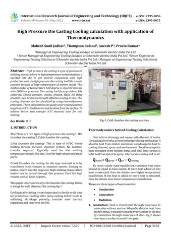
Thispaperisforspecificallycoldchamberdiecasting.Below isimageforcoldchamberdiecastingfig 1
Coolingindiecastingisveryimportanttodecidecycletime forproduction.Coolingsolvemanycastingdefectssuchas soldering, shrinkage porosity, controls steel thermal expansionandimprovesdielife.
HeatisformofenergyandmeasuredintheunitofJoules. Diecastingdieworksasheatexchangerduringproduction.It absorbsheatfrommoltenaluminumanddissipatesheatto coolingchannel,sprayandenvironment.Totalheatinputis heat extracted from molten metal and total heat output is totalheattranspiredtospray,internaldiecoolingandtoair.
To reach steady state equilibrium condition heat input should be equal to heat output.If more heataddedorless heatisextracted,then dieattains newhigher temperature equilibrium.Iflessheatisaddedormoreheatisextracted, thendieattainsnewlowertemperatureequilibrium.
Therearethreetypesofheattransfers:
Convection
Radiation
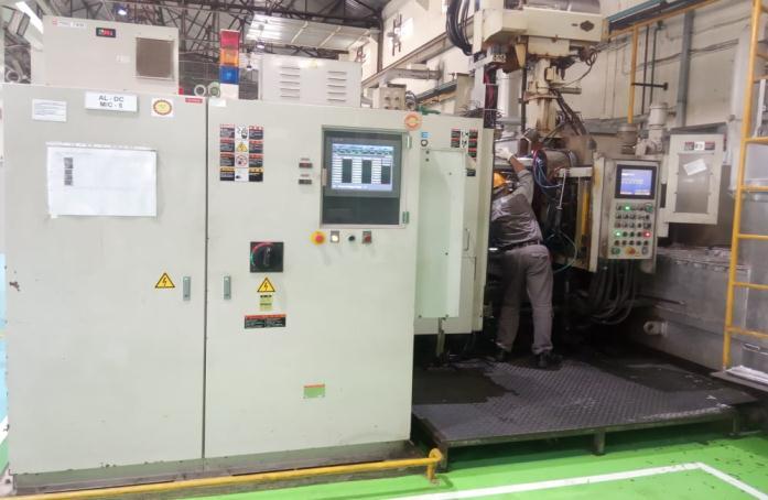
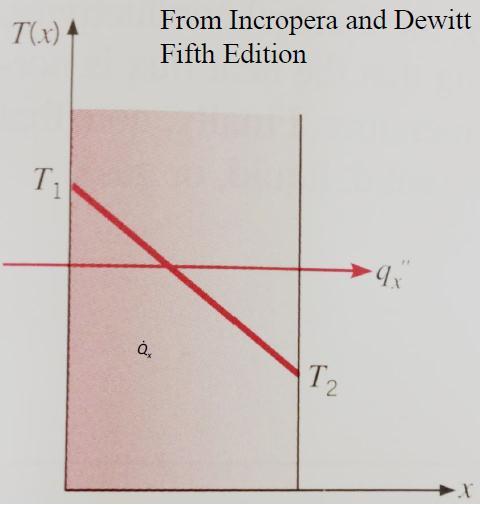
1. Conduction: Heat is transferred through molecules to moleculeswithoutmotion.Whendieabsorbsheatfrom moltenmetal,ittransfersheattoeverycornerofthetool byconductionthroughmoleculesofsteel. Fig 2shows howheattransfersinsteelfrompart.
From
International Research Journal of Engineering and Technology (IRJET) e ISSN: 2395 0056
Volume: 09 Issue: 05 | May 2022 www.irjet.net p ISSN: 2395 0072
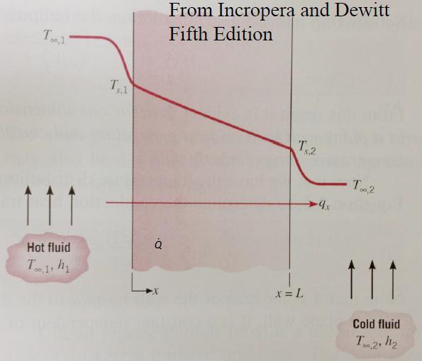
2. Convection:Heattransferredduetomassmotionof the fluid.Heat transferred by convection from die steel tocoolingchannels.Thisisthemosteffective heattransfermode.Heatlossduringcavityfillingis by convection. Heat transferby cooling channel is shownbyfig 3
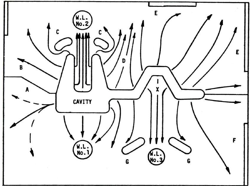
Heattransferratethroughconvectioncanbecalculatedby belowformula: Q= hA(Ts Tf) Q=Heattransferratein(Joules/sec) h=Heattransfercoefficient A=Areaofsurface Ts=Surfacetemperature Tf=Fluidtemperature
To calculate Heat transfer coefficient, we should know Reynold Number and Prandtl Number for specific cooling channel.
International Research Journal of Engineering and Technology (IRJET) e ISSN: 2395 0056
1. ReynoldsNumber: Re= v*D*ρ µ
2. PrandtlNumber: Pr=Cp*μ k
Where
V=Velocityoffluid
D=diameterofcoolingchannel
ρ=Densityoffluid
μ=DynamicViscosityoffluidinKg/sm
Cp=Specificheatoffluid
K=Thermalconductivityoffluid
By using above to Number, we can calculate heat transfer coefficientbyusingDittus Boelterrelationshipasfollows
Considering Reynolds Number more than 2300, we have followingequation:
Nu =0.023*Re 0.8*Pr 0.3 andHeattransfercoefficientas h= Nu*K D So h =0.023*Re 0.8*Pr 0.3*K
D
3. Radiation: Heat transferred by radiation from sourcetoatmosphere.Indiecastingheattransferred throughradiationisverylessmaximum2%.
Heat Load To DCD:
Total heat load to die casting die is the summation of latentheatandsensibleheat.
Qtot = QL + Qs
Qs Sensible Heat:
This is the heat required to raise the temperature of substance.
ORheatreleasedduringloweringthetemperature. Thiscanbecalculatedbyfollowingformula:
Qs=m*Cp*(Ti Te) Where,
Qs=Sensibleheatenergy(Joules) m=massofmaterial(Kg)
Cp=materialspecificheat Ti=InjectionTemperature Te=Ejectiontemperaure
This is the heat required to change the state of the substance(solidtoliquid) ORheatreleasedduringchangeof stateofthesubstance(liquidtosolid). Thiscanbeclaculatedasfollows:
QL=m*Lf
Where,
QL=Latentheat(Joules) m=massofmaterial(Kg) Lf=materiallatentheatoffusion
Cooling Calculation:
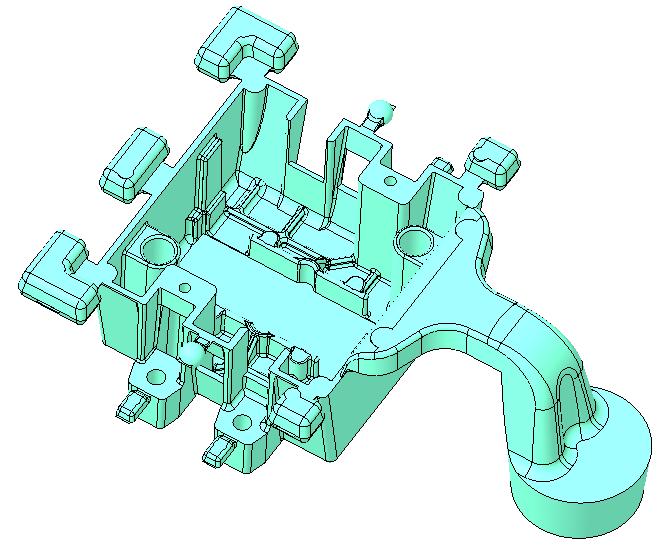
Consideringonediecastingtoolexample,wewillcalculate coolingchannellengthanditspositioninthedie. Casting ContactorHousing
WeightoftheCasting 400gm Moldingmaterial Aluminum Diematerial H 13 MachineTonnage 250Ton
Belowdatacapturedfrom3DsoftwareCreo. Volumeofshot 287.85cm3
Totalsurfaceareaofshot 1153.31cm2
Volume: 09 Issue: 05 | May 2022 www.irjet.net p ISSN: 2395 0072 © 2022, IRJET | Impact Factor value: 7.529 | ISO 9001:2008 Certified Journal
International Research Journal of Engineering and Technology (IRJET) e ISSN: 2395 0056
Volume: 09 Issue: 05 | May 2022 www.irjet.net p ISSN: 2395 0072
Volumeofcastingwithoverflow 176.87cm3
Surfaceareaofcastingwithoverflow 957.84cm2
Surfaceareaformovingside=446.9cm2
Surfaceareaoffixside=386.04cm2
Projectedareaonmovingside=14163.9mm2
Projectedareaonfixside=18128.9mm2
Inputsfrommachine:
Cycletime=25sec
InjectiontemperatureTi=660°C
EjectiontemperatureTe=425°C
Cavitysurfacetemperature=220°C
Watertemperatureinletforcore&cavity=25°C
Calculate heat transfer coefficient for specified cooling channelconsideringmachinewaterflowrateof3lpm.
Coolingmedium=water DiameterofcoolingchannelD=10mm=0.01m
VelocityoffluidV=0.64m/sec.
ThermalconductivityoffluidK=0.58(w/mk)
Densityoffluidρ=996.3(kg/m3)
Dynamicviscosityoffluidμ=0.0008684(Ns/m2)
Specificheatoffluid=Cp=4072.7(J/Kg/K)
Calculate Reynold Number: Re=VDρ/μ =0.64*0.01*996.3/0.0008684 =7342.6
Calculate Prandtl Number: Pr=Cp*μ/k =4072.7*0.0008684/0.58 =6.097
Calculate Heat transfer Coefficient h: h=0.023*Re 0.8*Pr 0.3*k/D =0.023*(7342.6)0.8*(6.097)0.3*0.58/0.01 =2840.45W/m2K
Calculate Total heat input to the die steel:
Considermaterialdata: Liquidustemperatureofmaterial:580°C Solidustemperatureofmaterial:507°C Dietemperaturearoundwaterline:120°C
Calculateweightofmoltenaluminumoncoreside&cavity side:
Weightonmovsidemm =Volume*Density =446.90*0.1847*0.00125 =0.1031Kg.
Weightonfixsidemf=Volume*Density =386.04*0.1847*0.00125 =0.089Kg.
Calculate Total Heat Input: Considerheatinputforeachcycleso=n=1/25=0.04
TotalHeatInput=LatentHeat+SensibleHeat.
LatentHeatforAluminum=389000J/Kg
Followingdataforaluminum:
Specificheatforaluminum:963J/Kg/C
Sensibleheatpersecond=n*m*Cp*(Ti-Te)
TotalHeatonmovside:
Qmov=Ql+Qs =n*mm*Lf+n*mm*Cp*(Ti-Te) =(0.04*0.1031*389000)+(0.04*0.1031*963*(660-425)) =2538.78Watt
TotalHeatonfixside: Qfix=Ql+Qs=n*mf*Lf+n*mf*Cp*(Ti-Te) =(0.04*0.1031*389000)+(0.04*0.089*963*(660-425)) =2193.06Watt
Calculate Length & Position of water line:
1. Length of water Line required for mov side: Consider below heat transfer through convection equation: Q= hA(Ts Tf) Where A=πDL
D=coolingchanneldiameter
L = Length of channel required to maintain cavity surface temperature
L=Q/(hπD(Ts Tf))
L=2538.78/{2840.45*π*0.01(120 25)} L=299.53mm
2. Depth of cooling line from surface for mov side: Considerbelowheattransferthroughconductionequation: Qx=KA(T1 T2)
2022, IRJET | Impact Factor value: 7.529 | ISO 9001:2008 Certified Journal |
International Research Journal of Engineering and Technology (IRJET) e ISSN: 2395 0056
Volume: 09 Issue: 05 | May 2022 www.irjet.net p ISSN: 2395 0072
Also, we express our deep sense of gratitude and appreciationtoourH.O.D. Mr. G A Reddy formotivatingus towritethispaper.
K=ThermalconductivityofH13material=0.0273w/mm°C D=0.0273*14163.9*(220 120)/2538.78
Depthfromsurface=15.23mm Fix side: Calculateinsamemannerforfixside
1. Lengthofcoolingchannelforfixside:258.74mm 2. Depthofcoolingholefromcavitysurface:22.56mm
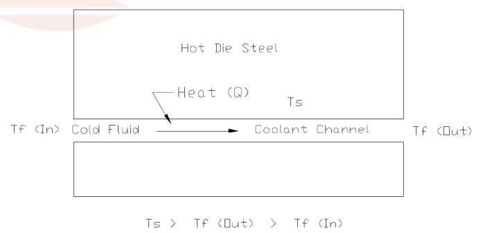
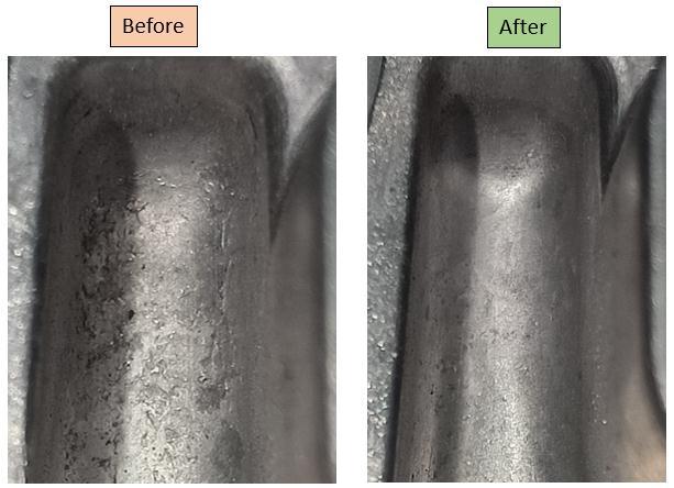
Aftercoolingcalculation,wefoundrequiredcoolinglength anditslocationfromdepthtoachieverequiredcycletimefor bestproduction.Inoldertooldesigncoolingchannelfound as 250mm for mov side and 200 for fix side. Now this channelmodifiedtoachieve300formovsideand260forfix side.Itsolvedsolderingprobleminthecasting.Referbelow Fig 4imageforbetterunderstandingsoftheresult.
[1] E.AHerman,1979,DieCastingDies(NADCA)SocietyOf DieCastingEngineers,USA.
[2] EC 415DieCoolingsystemEngineering,NADCA,USA
[3] Mike Ward, EC 506 Engineering Die casting Dies, NADCA,USA
[4] “Engineering properties of aluminum alloys 1981, International Lead Aluminum Research Organization, NewYork(Vol.5).
Mr. MAHESH SUNIL JADHAV
Working as Manager Tool Design Dept, ETS, ATL Schneider Electric IndiaPvtLtd, Ahmednagar,Maharashtra.
Mr. Thompson Roland


Working as Sr. Manager Tool Design Dept, ETS, VTL Schneider Electric India Pvt Ltd, Vadodara, Gujarat
Mr. Aneesh P.
Working as Sr. Engineer Tool Design Dept, ETS, VTL Schneider Electric India Pvt Ltd, Vadodara, Gujarat
Fig 4 TrialSampleCastingImage

Iwouldliketoacknowledgetheassistanceofseveralpeople, whoplayeddecisiveroleinwritingthispaperwiththehigh technicalimpact.
Wetakethisopportunitytoexpressourrespectfulregards to Mr. Rajesh Aggarwal forguidingusaboutsciencebehind diecastingdies.
Mr. PRAVIN KUMAR
Working as Manager Tool Design Dept, ETS, ATL Schneider Electric IndiaPvtLtd, Ahmednagar,Maharashtra.