International Research Journal of Engineering and Technology (IRJET) e ISSN: 2395 0056 Volume: 09 Issue: 05 | May 2022 www.irjet.net p ISSN: 2395 0072

International Research Journal of Engineering and Technology (IRJET) e ISSN: 2395 0056 Volume: 09 Issue: 05 | May 2022 www.irjet.net p ISSN: 2395 0072
SeismicevaluationofstrengthenedConcrete(RCC) homesare one of the studies pastimes in recent times and it's far due to thefact of,earthquakereasons plentyofharmandlosseswith appreciate to existence and harm of structures. The gift observeisconstrainedtostrengthenedconcrete multi storied residential constructing beneath have an impact on of earthquake floor motions. In this observe, a nonlinear time records evaluation is carried out on G+8 storey RCC constructing body thinking about time records the use of ETABS software. Analysis additionally carried out to observe the conduct of constructing beneath the seismic and gravity hundreds as in step with the IS:1893 2016. All evaluation are as compared for results inclusive of storey displacements and base shears. From the observe it's far encouraged that evaluation of multistoried RCC constructing the use of Time History approach turns into essential to make certain protection towards earthquake force
Key Words: Time History Analysis, Story Drift, Base Shear, Earthquake Load.
Now a day’s Earthquake has multiplied because of excavationanddifferentsources.Earthquakeisthebiggest supplyofcasualtiesandreasonsdamagesininhabitedareas. Great efforts have been madein latest yearsfor fixing the hassleofconstructinglayoutinseismicareas;noshapecan absolutelydisposeofharmfromearthquakes.Theimportant motive of earthquake resistant creation is to construct systems that carry out higher at some point of seismic interestthantraditionalcreation.Accordingtoconstructing codes,earthquake resistantsystemsaresupposedtofaceup tothebiggestearthquakeofapositivechancethisisinall likelihood to arise at their location. This manner that systems ought to be capable of face up to minor stage earthquakes with none damages, mild stage earthquakes withafewnon structuralharminanefforttoberepairable andfundamentalstageearthquakewithoutcollapse
Themainobjectiveofthepresentstudyistocarryoutthe seismicresponseof8storeyRCCframestructureusingtime historyanalysismethods.Thespecificobjectivesareasgiven below
TostudythecomparisonofperformanceofFixedBase Building using published work as a reference and understandsthebehavioralaspects.
Todevelopasimplifiedmodelofamultistorybuilding with identical parameters and simultaneously providingitwithbaseisolationandviscousdamper.
Tocarryoutdynamicseismicanalysisonthemodeled buildings using scaled records of acceleration time historiesandcomparingtheirresults.
Seismic non linear time history analysis of multi storied RCC building under influence of different earthquakesusingEtabs.
To study the behavior of multi storied RCC building under the action of load combination (seismic loads andgravityloads).
The time history analysis is performed for the RCC building firstly and then the seismic analysis is performedforloadcombination(DL,LL,andEQL).
Analysisofbaseshearanddisplacementondifferent storey.
To compare seismic behavior of multistoried RCC framedbuildingfordifferentearthquakesintermsof various responses such as, base shear and displacements.
The entire process of modeling and analysis of all the primary elements for all the models are carried by using ETABS2020nonlinearversionsoftware
ETABissoftwareprogramevolvedwiththeaid ofusingmaintainingtargetedonevaluationandlayoutofthe constructing structure. Its person interface is likewise pleasantandsmoothtouse.Ithasfunctionalitytoaddress eacheasyinadditiontomaximumcomplicatedconstructing model, which incorporates a giant sort of linear and non linear behaviors, which turns into a device for structural engineerswithinsidetheindustry.Usinganotunusualplace database, it may combine modeling, analytical and layout
International Research Journal of Engineering and Technology (IRJET) e ISSN: 2395 0056
procedures; it additionally capabilities an intuitive and effectivegraphicalinterface
Theanalysisproceduresarefurtherclassifiedasgiven below:
1.Linearstaticanalysis
1.1.Equivalentstaticmethod
2.Lineardynamicanalysis
2.1.Responsespectrummethod
2.2.Elastictimehistorymethod
3.Nonlinearstaticanalysis
3.1.Pushoveranalysis
4.Nonlineardynamicanalysis
4.1.Inelastictimehistorymethod
Thistechniqueoffersusthemaximumcorrectsolutionandis maximumstate of the arttechniquefordynamicevaluation of buildings. Time records evaluation is a grade by grade system of the dynamic reaction of the shape to a specific loadingwhichcouldrangewithtime.Thistechniquesolves the equation of movement through grade by grade direct integration over a time c language with displacements, velocities and accelerations of preceding step serving as preliminaryfunction.
M +C +KU=F(t)
TherearemanycaseswhichcanbeperformedusingTime HistoryAnalysis,whichisas:
1. Linearvs.Non Linear
2. Modalvs.DirectIntegration
3. Transientvs.Periodic
As per IS 1893 (Part I):2002 the following load combinations are considered in limit state design of reinforcedcementconcretestructureduringtheanalysisof themodel:
a)1.5(DL+LL)
b)1.2(DL+LL EL)
c)1.5(DL EL)
d)0.9DL 1.5EL
TheaboveequationcanbefurtherexpressedforELinxand ydirectionsareasfollows: i)1.5(DL+LL) ii)1.2(DL+LL EX) iii)1.5(DL+EX) iv)0.9DL 1.5EX v)1.2(DL+LL EY) vi)1.5(DL+EY) vii)0.9DL 1.5EY
2.2 Design steps for Fixed Base Building:
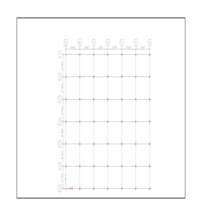
G+8 storied constructing is modeled the use of concrete beams, columns, slabs, infill wall and stairs. It has given a geometry form of rectangle with plan dimensions of 30mX24m.ItisloadedwithDead,LiveandSeismicForces [accordingtoIS:1893(PartI):2002].Itisthenanalyzedthe useofTimeHistoryMethodforearthquakeregionVofIndia (ZoneFactor=0.36).Theinfoofthemodeledhomesareas follows:Modal dampingof 5%is taken into consideration with SMRF (Response Reduction Factor, R = 5) and ImportanceFactor(I)=1.ETABSisusedto documentthe overall performance of fashions to give a quick concept approximately the position of base isolation and fluid viscous damper in shielding the shape in opposition to earthquake hazards. The following assumptions had been madeearlierthanthebeginofthemodelingtechniqueinan efforttokeepcomparablesituationsforallofthefashions:
a)Onlytheprincipleblockoftheconstructingistaken into consideration. The staircases aren't taken into considerationwithinsidethelayouttechnique
b) The important cognizance is at the reaction of the bodyconfiguration,becausetheconstructingisforuse forresidentialpurposes.
c) The ground is resting at once at the floor, so slabs aren'tsuppliedonthefloorground.
d)Thebeamsarerestingcentrallyatthecolumnsinan efforttokeepawayfromthesituationsofeccentricity. ThisiscarriedoutroutinelyinETABS.
e)Forallstructuralelements,M25&Fe415isused.
Volume: 09 Issue: 05 | May 2022 www.irjet.net p ISSN: 2395 0072 © 2022, IRJET | Impact Factor value: 7.529 | ISO 9001:2008 Certified Journal | Page3367
International Research Journal of Engineering and Technology (IRJET) e ISSN: 2395 0056
f)Thefootingsaren'tdesigned.Supportsareassigned withinsidetheshapeofconstantsupports.
g)Seismichundredsaretakenintoconsiderationwith insidethehorizontalpathonly(X&Y)andthehundreds inverticalpath(Z)areassumedtobeinsignificant.
h)Unitweightofconcreteandbrickare25KN/m3and 18KN⁄m3respectively.
Table : Member Properties & Specifications for the Models Sizes of the member are as follows:
1 PlanDimensions(X Y) 30m 24m 2 FloortoFloorHeight(Z) 3m 3 TotalHeightofBuilding(G+8) 27m 4 TypeofStructure SMRF 5 SoilType(asperIS:1893(Part 1) 2002) Medium 6 Response Reduction Factor 5 7 Importance Factor 1 8 Seismic Zone Factor 0.36(ZoneV) 9 Grade of Concrete&Steel M25&Fe415 10 BeamSize 0.30m 0.50m 11 ColumnSize 0.30m 0.60m 12 SlabThickness 0.150m 13 WallThickness 0.200m 14 Staircase
Rise 0.120m Thread 0.350m Width 1.5m Stringer 0.160m 15 LoadCombination According to IS : 1893 (Part 1) :2002 16 LoadsApplied
DeadLoad Calculated as per SelfWeight FloorFinish 1KN/m2 LiveLoad 3KN/m2 SeismicLoad Calculated as per IS: 1893 (Part 1) 2002
2.3 Steps involved in design of fixed base building are as follows:
STEP 1: Lumped mass calculation of various floor levels
Atrooflevel:(M9)
Weight of structure at roof level (W9) = weight of slab + weightofbeam+weightofcolumn+weightofwall +imposedload =2700+1417.5+330.75+2041.2+0=6489.45KN
Massofstructureatfloorlevel(M9)= =661.5tone
Forotherstories:(M1=M2 =M3 =M4 =M5 =M6 =M7 =M8)
Weightofslab=25×0.15×24×30=2700KN
Weightofbeam=25×0.3×0.5[30×7+24×7]=1417.5KN
Weightofcolumn=49(25×0.3×0.6×3)=661.5KN
Weightofwall=18×0.2(30×7+24×7)×3=4082.4KN
Weightoffloorfinish=1×24×30=720KN
Liveload=3×30×24×3×0.25=540KN
Weightofstructureforotherstories(W1) =weightofslab+ weightofbeam+weightofcolumn+weightofwall +Liveload+floorfinish =2700+1417.5+661.5+4082.4+540+720=10121.4KN
Massofstructureforotherstories(M1)= =1031.74tone
Note: Theearthquakeforcesshallbecalculatedforthefull deadloadplusthepercentageofimposedloadasgivenin Table8ofIS1893(Part1):2002.TheimposedloadonRoof isassumedtobezero.25%ofimposedload,ifimposedload isupto3KN/m2
Seismic Weight of the building= 8×10121.4 +6489.45 = 87460.65KN
Massofthebuilding=8915.45tone
STEP 2: Determination of fundamental natural period
Ta =0.09
Where,h=heightofbuildinginmeterand d =base dimension of the building at the plinth/groundlevelinmeteralongthe considereddirectionofthelateralforce.
Tax = 0.09 = 0.44 second, Tay = 0.09 = 0.49 second
STEP 3: Determination of Design Base Shear
Designseismicbaseshear,VB =Ah W
Ah = = × ×2.5=0.09
Volume: 09 Issue: 05 | May 2022 www.irjet.net p ISSN: 2395 0072 © 2022, IRJET | Impact Factor value: 7.529 | ISO 9001:2008 Certified Journal | Page3368
International Research Journal of Engineering and Technology (IRJET) e ISSN: 2395 0056 Volume: 09 Issue: 05 | May 2022 www.irjet.net p ISSN: 2395 0072
=2.5,accordingtoIS1893(PartI):2002
VB =0.09 87460.65=7871.45KN
The design base shear (VB) computed shall be distributed alongtheheightofthebuildingaspertheexpression, Qi =VB Where,Qi =Designlateralforcesatfloori, Wi =Seismicweightsofthefloori, hi =Heightofthefloori,measuredfrombase,and n=Numberofstories Q1 =27.62KN,Q2 =110.48KN,Q3 =248.57KN,Q4 =441.90 KN,Q5 =690.48KN,Q6 =994.29KN,Q7 =1353.34KN,Q8 = 1767.62KN,Q9 =2237.15KN
STEP 5: Total Lateral Stiffness of each story k1=k2=k3=k4=k5=k6=k7=k8=k9=49 ( )I=k E=5000 =5000 =25000N/mm2 , I= =0.0054m4 , L=3m k=2.94 106 KN/m.
Fig: Plan view of G+ 8 Residential building model
3.1 Description of Models :
Model =TimeHistoryAnalysisofFixedBaseBuilding
3.1.1 Building Details :
a) PlanDimension=30m 24m b) HeightofBuilding=27m(G+8) c) HeightofeachStory=3m d) BuildingType=Residential
3.1.2 Material Properties :
a) Gradeofconcrete=M25 b) Gradeofsteel=Fe415andFe250 c) Densityofconcrete=25KN/m3 d) Densityofbrickinfillwall=18KN/m3
3.1.3 Section Properties
a) Beamsize=300mm 500mm b) Columnsize=300mm 600mm c) SlabThickness=150mm d) WallThickness=200mm
3.2 Load Consideration:
3.2.1 Gravity Load: a) DeadLoad=Beam,Column,Wall,Stair, Slab b) LiveLoad=3KN/m2 c) FloorFinish=1KN/m2
3.2.2 Various terms used in Time History Analysis: a) SeismicZone=Zone5 b) SoilProfiletype=Medium c) ResponseReductionFactor=5.0 d) ImportanceFactor=1.0 e) Damping=0.15 f) Zonefactor=0.36
Seismicnon lineartimehistoryanalysisofamultistoriedRC buildingearthquakes iscarriedout.Fromthepresentstudy thefollowingconclusionscanbedrawnout.
In Time History Analysis, The Base Shear of the Structure by manual method is more than the value givenbyEtabs Themaximumlateralforcesis7871.45 KN&7820.3408KNrespectively.
BaseShearofStructureasperEtabsresultis99.35% manualmethod.ThisReductiondecreasestheground motion,whichmakesthestructuremorestable.
© 2022, IRJET | Impact Factor value: 7.529 | ISO 9001:2008 Certified Journal | Page3369
International Research Journal of Engineering and Technology (IRJET) e ISSN: 2395 0056
Volume: 09 Issue: 05 | May 2022 www.irjet.net p ISSN: 2395 0072
InTimeHistoryAnalysis,TimePeriodofthestructure thevaluegivenbyEtabsismorethanmanualmethod, which gives more time for the structure to react duringearthquake.
5. RomyMandPrabhaC(2011),“DynamicAnalysisof RCC Buildings with Shear Wall”, International Journal of Earth Sciences and Engineering, ISSN 0974 5904,Vol.04,659 662.
Fromthisstudy,ithasbeenfoundthatdisplacement increases on higher floors, which make higher floor morecriticalascomparetolowerstory.
6. ShahaVandKarveS(2010),“IllustratedDesignof Reinforced Concrete Buildings”, Sixth Edition, StructuresPublication,Pune.
Stiffnessofthebuildingisfoundtobemorenearthe ground and its value decreases as the distance increasesfromground.Thismakeitmorestablenear the ground and result in less displacement in lower stories.
7. Patil A.S, Kumbhar P.D,“Time history analysis of multistoried RRC building for different seismic intensities”,InternationalJournalofStructuraland CivilEngineeringResearch,vol. 02,issue 03,Aug 2013.
From results it is observed that the storey shear is decreased as height of the building increased and reduced at top floor in all the building models subjected to seismic loads considered. The storey shearismaximumatthebase.
8. Bhagwat Mayuri D, “Comparative study of Performance of multistoried building for Koyna and Bhuj earthquake by THM and RSM”, International Journal of Advanced Technology in Engineering and Science, vol.no. 02, issue 07, ISSN:2348 7550,July2014.
As time history is realistic method, used for seismic analysis, it provides a better check to the safety of structuresanalyzedanddesignedbymethodspecified byIScodeResultsfromvarioustimehistoriescanbe efficientlypresented andutilizedfor future building design problems. Standards can be established for same.
9. Dubey S.K, Sangamnerka Prakash, Agrawal Ankit, “Dynamic analysis of structures subjected to earthquakeload”,InternationalJournalofAdvance Engineering and Research Development, vol. 02, issue 09,ISSN:2348 4470,Sep.2015.
Forimportantstructurestimehistoryanalysisshould be performed as it predicts the structural response moreaccuratelyincomparisonwithothermethods.
The results should be the same but as software calculationstendstorequirelesseffortoncetheyare setuptheyusuallycalculatemoreloadcases.where asanengineerthatdoeshisworkbyhandwilltryto worksmarterandidentifythekeysectionsandload casesandsolimittheamountoftheworkrequired.
1. Anil K. Chopra. “Dynamics of Structures” Theory andApplicationtoEarthquakeEngineering,Third Edition.
2. ASCE/SEI 7 05 Minimum Design Loads for BuildingsandOtherStructures.
3. DuggalSK(2010),“EarthquakeResistanceDesign of Structure”, Fourth Edition, Oxford University Press,NewDelhi.
4. HaseltonCBandWhittakerAS(2012),“Selecting and Scaling Earthquake Ground Motions for PerformingResponse HistoryAnalyses”,The15th WorldConferenceonEarthquakeEngineering.
© 2022, IRJET | Impact Factor value: 7.529 | ISO 9001:2008 Certified Journal | Page3370