International Research Journal of Engineering and Technology (IRJET) e-ISSN: 2395-0056

Volume: 09 Issue: 05 | May 2022 www.irjet.net p-ISSN: 2395-0072
International Research Journal of Engineering and Technology (IRJET) e-ISSN: 2395-0056
Volume: 09 Issue: 05 | May 2022 www.irjet.net p-ISSN: 2395-0072
*1 Bijay kumar sah, 2Keerthana Rathinavel, 3Naveenkumar. M, 4Ashir Azar , 5Dr.Venkatesan Saradha Paramashivaiah
1,2,3,4 UG, Final year student, Department of Aeronautical engineering, Excel engineering college 5Associate Professor (HOD), Department of Aeronautical engineering, Excel engineering college Salem Main Road, Komarapalayam, Namakkal 637303, Tamilnadu, India ***
Thedesigningandanalysingoftheprocessiscarried outona supersoniccommercial aircraftwith delta wing configuration, which aims to provides depth knowledge of aircraft gross weight calculation, fuel weight, empty weight, wing span, wing area, aspect ratio, lift to drag ratio. As using Carlson method, we get sonic boom overpressures and signature duration results. A simplified method of calculation of sonic boom is been performedbothnumericallyandanalytically.
The numerically predicted results are in good agreement with that of experiment data. Sonic boom overpressures and N wave signature duration has been predictedforthe entireaffectedgroundarea foraircraft in level flight path using Carlson theory. In this both theoretical and computational aspect of aerodynamic, structure, propulsion and weight values of an entire aircraft are calculated for the design. Modelling of aircraft is carried out using CATIA V5 where computational method is been performed using ANSYS FLUENTsoftware
Keywords: Supersonic, Aerodynamic aspect, Commercial aircraft, Computational analysis, Carlson theory
Overthelastfewyears,airtraffichasseena high increase in capacity, range and efficiency. In addition to these, the need for a faster aircraft. Carry of people and other payloads over a longer distance within a shorter interval of time will be the aim of the most airline industry in the near future. Conceptual design of an aircraft involves many different steps. The Commercial Supersonic aircraft is Structure using CATIA V5 and analysis is been carried out using ANSYS FLUENT software.Thisprogramwasmadeupofcomponentsthat evaluated each performance parameter of the aircraft whilesolving forthesmallestmaximumtake offweight. Reducing noise and disturbance, this boom signature is tobelimited.
Creation of an environmentally friendly aircraft is an important design parameter. The high Mach number which the Supersonic aircraft will travel at will create thesonicboomoverpressureatsealevel.Reducingnoise and disturbance, this boom signature must be limited. Work wasdonetoanalyseandchoosethemostefficient aerodynamic shape. The sonic boom of the aircraft was approximated using methods described by Carlson. Whereas, Sonic boom approximation by Sea bass provided a rough estimate of boom overpressure using simplyaircraftweight,morein depthanalysiswasdone using Carlson which considers geometric parameters and area distribution of the aircraft. Iteration of design yields an aircraft that satisfies the design mission of 4600km cruise, and an overpressure of 0.547. Control surface area is estimated by using analysis done by Dr. Roskam. The necessary surface area of the delta wing is determinedusingsimplenumericalapproximations.Key constraints necessary for the aircraft to operate safely under normal flight conditions were analysed for the aircraft configuration. From the thorough analysis of aircraft component create a concept that both satisfied majorrequirementssetintheopportunitydescription.
Since the retirement of Concorde's airline service in 2003, there is no more civil supersonic transport. The environmental concerns (sonic boom, noise, emissions, etc.) raised by Concorde have been the major barriers for future civil supersonic aircraft. The fundamental problempreventingthereturnofsupersonicflightisthe sonic boom at ground level. However, the public's perceived acceptance of the sonic boom intensity is still uncertain. Since the weight and size of a supersonic aircraft have first order effects on the intensity of the sonic boom signature, it has been deemed nearly impossibletocreatealow boomlevelwithaheavierand largerconventional aircraft.Though,fora wide rangeof customers the low price airline is attractive, there still exist customers who attribute great value to time. Recognition of the value of time has led to increased interest in the feasibility of supersonic business jets. Double the cruise speed could result in half the time in theair.
International Research Journal of Engineering and Technology (IRJET) e-ISSN: 2395-0056
Volume: 09 Issue: 05 | May 2022 www.irjet.net p-ISSN: 2395-0072
Operational flexibility, safety and privacy working environment,andadequateambienceforfosteringsocial contacts add value to supersonic business jets. The unit priceanddirectoperationcostsshouldbeviableforboth manufacturers and customers. The interest of supersonic civil flight is not only driven by enterprising human spirit or profit seeking but also by technology itself. The basic technical capability for the supersonic cruise has existed for decades and the technology has improved considerably since Concorde. The variable cycle engine concept and acoustic problems caused by the inlet and nozzle require more development to be solve. Sonic boom mitigation concepts still need further ground and flight testing. Therefore, environmentally friendly, economically viable and tech nonlogically feasible characteristics are required for any future super sonic airliner. There have been prominent publications on supersonic aircraft design review. The National Research Council analysed the design challenges and critical solutions appropriate to supersonictransport.
ThisaircraftsetsthecertainvalueofMachno.1.6, design range of 4600km with passengers accommodate of48and4crewmembers.Also,the aircraftisexpected toachievesupersoniccruise efficiency,have a low sonic boomandhighliftfortake offorlandingmakinggrowth to the aviation industry. As, the requirement of the supersonic commercial aircraft is much in need so the designwillleadtothemassivegrowth.
It is cost effective, advance and fastest mode of transport. It’s expected to hold total number of 52 passenger including crew members. Sonic boom overpressure is estimated to be of 0.547 psf for the designed supersonic commercial aircraft with a signaturedurationof0.3sec.
Tupolev Tu 144 was known to be the first supersonic transport aircraft introduced two months beforetheConcordewitha cruisespeedof2,200km/hr (1,400 mph, Mach 2). The design of both the airliner were slightly similar with same delta wing design configuration.Itsregimeendedsoonasitexperiencedan in flight failure during a pre delivery test flight, crash landing on 23 May 1978 with two crew fatalities. As of now the last two remaining aircraft is in Gromov Flight ResearchInstituteinZhukovsky.
Secondlythe British French supersonic passenger aircraftwiththeMachspeedof2.04wasfirstintroduced on 21 stJan 1976. It took its first flight on 2ndmarch 1969
and retired in the year 2003. Companies like Airbus, Sud Aviation(Aerospatiale),BritishAircraftCorporation (BAC), Rolls Royce/ SNECMA etc. were join under the Anglo French treaty for manufacturing Concorde. Total number of 20 aircraft were built including 6 non commercial aircraft. Concorde lasted in service for 27 years until 25thJuly 2000 when Air France flight 4590 wascrashedandkilled113people(109onaircraft,4on ground).Theaccidentwascausedbyapieceofmetalleft on the runway after falling from a continental jet. Therefore, after three years of accident the Concorde was retired in the year 2003. The total seating capacity of the aircraft was about 92 128 passengers, 3 crew members. Range of these aircraft was 7,222.8 km, cruisingspeed of2,180 km/ hr(1,354mph,Mach2.04). Where, the maximum cruising altitude of the Concorde was 60,000ft (18,300m). Concorde was the only aircraft thattravelfasterthanthespeedofthesound.Becauseof thistheairpressureandfrictioncouldreallyheatupthe aircraft.So,Concorde was madeupofhighstrengthand high temperature aluminium alloy named RR58. The temperature at the nose was the highest about 127 degreesCelsiusandwas91degreesCelsiusattheendof thefuselage.
Overthese ongoingyears wecanvisualizetheairtraffic hasseenahighincreaseincapacity,rangeandefficiency. In addition to these, the necessity for a faster aircraft is essential at the present time. Transportation of people over a longer range within a minimum amount of time willbethemaingoaloftheairlineindustryinthecoming future. There are many current ongoing projects like BOOM, SPIKE, Lockheed Martin X 59 Quest expertizing inthisfieldwhichareexpectedtobeonservicetill2024 laterorsooner.
Sinceovertheseveralyearstherehasbeenasupersonic stagnationfordecades,researchonsupersonictransport hasneverstopped.Basedonthefailuresoftheprevious SST program, NASA was given the responsibility to establish the technology base for a viable supersonic cruise aeroplane. As part of the effort, the Supersonic Cruise Research (SCR)program was carried out from 1971to1981.TheVariableCycleEngine(VCE)program, a propulsion offshoot of SCR, was conducted from1976 to1981tostudythepromisingVCEconcepts.Feasibility studiesforthenext generationSST wereinitiatedinthe late 1980s. The highspeed Research (HSR) program beganbyNASAin1989,includingin depthstudiesfrom 1995withTu 144testflights.
The High Speed Civil Transport (HSCT) program, the focus of HSR program, aim developing a 300 passenger, Mach 2.4 supersonic airliner. The pro gram terminated in 1999 on account of environmental challenges and budget problems. The Quiet Supersonic Platform (QSP) was conducted by the US Defence Advanced Research Projects Agency (DARPA) from 2000 to 2006, aimed at
International Research Journal of Engineering and Technology (IRJET) e-ISSN: 2395-0056
Volume: 09 Issue: 05 | May 2022 www.irjet.net p-ISSN: 2395-0072
developing a low boom (0.3 PSF) supersonic aircraft both for military and civil applications. In Europe, the next generation supersonic research program was initiatedin 1994 but wasstoppedinthesame period as the HSR program because Europe turned to a large aeroplane. High Speed Aircraft (HISAC), also called environmentally friendly High Speed Aircraft, was conductedfrom2005to2009toresearchthetechnology baseofasmall sizeenvironmentallyfriendlysupersonic transport. Japan Aerospace Exploration Agency (JAXA) initiated a scaled supersonic experimental aeroplane project named NEXST (National Experimental Supersonic Transport) project [16]in 1996 so as to establish advanced design technologies for the next generation SST. The program ended in 2007. The Silent Supersonic Technology Demonstration (SSTD) program started in 2006 to validate MDO design tools and demonstrate the silent supersonic aircraft concept. The DroptestforSimplifiedEvaluationofNon symmetrically distributedsonicboom(D SEND)project[18,19]started in 2007 to drop models from balloons to validate the sonicboommitigationtechnology.Sinceseveraldecades ofResearch,itistransparentthatasmall sizesupersonic transport could be the first step into a modern supersonic era. The increasingly stringent noise requirements have created the need for the supersonic jettothequietsupersonicjet(QSJ)program.
Sir James Hamilton the designer of the Concorde OgivaldeltawingwasappointedastheBritainDirector General of the Concorde Project in 1966.This wing design led to cruise the aircraft at twice of speed of the sound, yet provide safe take off and landings. The feature of delta wing doesn’t operate the factors of low speedintake off,landingquitewell.So,Ogivaldeltawas thechangeforprovidinggreaterefficiencyatlowspeed. Tomaintain efficient liftat lowspeed(take off,landing) the angle of attack should be high, which leads to the drawbackofhighdragatlowspeedandflowseparation at high angle of attack. So, the modification was an update of slender ogival delta wing making the flow separation slow. The idea of slender delta wing was proposed by Kuchemann and Weber, they published referring the strong vortices produced on the upper surface by the delta wing at high angle of attack. The vortex leads to the cause of increase lift, lowering air pressure.Weberfoundthatwiththeincreaseinlengthof the wing, lift from the vortex will be increased. Thus, leading to extend the wing along the fuselage. This designledthedrawbackoflowspeedwhiletakeoffand landduetonosehightogeneratetherequiredvortexlift. Also,maximumpowerwasrequiredtoflyatalowspeed or high angle of attack. Flow separation or boundary layerseparationistheseparationofboundarylayerthat isformedbytherelativemotionbetweenthefluidanda solid surface (aerofoil). The flow type of boundary layer
can be calculated with the Reynolds no. Whereas, the laminarflowisindependenttotheReynoldsnumber,the turbulent flow increases with the increase in Reynolds number.Theflowtravelsforlongandstoppedatapoint and flow reverse, then the flow will be detached and forms of eddies and vortices leading to the increase in induced drag and reduction in lift. Which is generally caused by the pressure differential between front and rear.
Where for Tupolev the wing was replaced by Canard Delta with a double delta wing including spanwise and chordwisecamberaddingtwosmallretractablesurfaces (moustache canard). The advantage of this was to increase lift at low speed. The movement of elevons movingdownwardsinadeltawingincreasesthelift,but also pitches its nose downward. Placing the canards at the nose downwards moment thus helps reducing the landing speed of the production of Tu 144. It also had thefuelcapacityof98000kgto125000kg.
When the angle of attack is high the built in abilityproducesstrongvorticesovertheuppersurfaces, lowering air pressure and increasing lift. This effect is knownsasVortexLift.At,lowspeedtheairswirlingover the wing produceda bouncingmotion,ata frequencyof about half a second, which can sometimes mistake for lightturbulence.Thismotionsoondisappearedoncethe speed had increased after take off, but was during final approach. Supersonic aircraft used thinner aerofoil in order to reduce drag and was also designed to fly with separated vortex flow, which is also a method of lift generation. The wing area and the wing span of the aircraft was 358.25m2(3,856 sq. ft) and 84ft (25.6 m) respectively.Theseparatedvortexflowwillformacone shapedvorticeswhichmaycontrolseparationleadingto not stall and increase angle of attack up to 40 . The vortices will soon fall off at the higher angles. This method of lift generation took over 5000 hours of wing tunneltests
Shockwavesaregeneratedwhentheaircraftfliesatthe speed of the sound. The large pressure waves (750 miles/hr.) formed from the air flowing through the shock waves is the cause for Sonic Boom and are heard as a loud sound at the ground. Generally, the subsonic aircraftdon’tgeneratesonicboomasitfliesbelowspeed of sound and the air ahead of it makes a way before the aircraft reaches and avoids from the huge formation of pressure waves. Sonic boom generated by the Concorde was1.94psf(Poundspersq.ft),atspeedofMach2.
The Engine used in Concorde was Olympus 593 produced by the Rolls Royce and SNECMA. There are Total four number of Rolls Royce/SNECMA engine were used in the aircraft. Each engine generates 18.7 tons(180kn) of thrust and the total fuel burned by the fourengineswas6,771gallons(25,629litres)offuelper hour.
Concorde had the total number of seventeen fuel tanks that hold 31,569 gallons (119,500 litres) of kerosene fuel.ThefuelusedwasA1jetfuel.Theenginedimension was 1212 mm (47.75 inch) in diameter and length of 4039 mm (159 inch). Afterburning Kuznetsov NK 144 turbofan with a cruise SFC of 1.58 kg/kgp hr was the engineusedinTupolev
Material used in Tupolev was 15% titanium and 23% non metallic materials. Structural materials used were aluminum alloys, titanium or stainless steels. Concorde was made up of high strength and high temperature aluminium alloy named RR58. The temperature at the nose was the highest about 127 degreesCelsiusandwas91degreesCelsiusattheendof the fuselage. Thus, Concorde used high reflectivity white paint that having double reflective in comparison to the white paint that applied on the other jets. The head encountered by the Concorde caused the airframe to expand 7 inches (17.8 cm) in flight. Thus, special aluminium alloy (AV2GN) light weight and more heat resistant than titanium were used. This alloy having relatively low density i.e., 7.75g/cc. The various ComponentsforConcordeweremanufacturedbyseveral company of the UK and France, and there were two assemblylines,oneatFiltonandoneatToulouse.
A brief overview of key design parameters is given in table 1. The aircraft’s maximum take off weight of 66530.99lbs includes 48 passengers and 4 crew membersincludingluggage
DesignParameters Value Units
Aircraft(MTOW) 30177.95 Kg
Fuelweightfraction 0.299
Emptyweightfraction 0.522
Wingarea 132.201 m2
Winglength 14.689 M
Wingspan 18 M Rootchord 14.689 M
AspectRatio 2.4
Aircraftlength 120 Ft Tipchord 0 T/W 0.25 t/c 10%
MACdistance 3 M
MAClength 9.793 M
FuselageDiameter 2.87 M
Fig1:MACandCGlocation
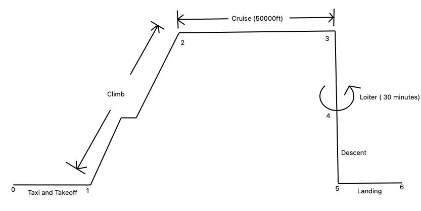
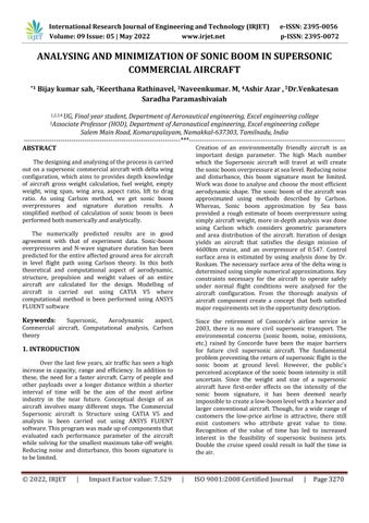
Fig2:AircraftDesignMission
International Research Journal of Engineering and Technology (IRJET) e-ISSN: 2395-0056
Volume: 09 Issue: 05 | May 2022 www.irjet.net p-ISSN: 2395-0072
aircraftisthreedimensional,thuswingshad athickness interpretedbythet/c ratio andthefuselagehada cross sectional area distribution predicted by the radial distributionovertheaircraftlength.
Theabovefig 2representsthetypicalmissionprofilefor the aircraft. This aircraft will climb to cruise altitude at bestrateofclimbrightaftertake off.Themissionprofile has accounted for air traffic control altitude restrictions in order to clear any traffic in the airspace if necessary. This is important especially when flying out from busy airportsthataremajorworldwidehubs.Theaircraftwill thencontinueinasteadylevelcruisefor1227.63mphat an altitude of 50000ft. The especially high altitude is essential to the achievement of a low sonic boom overpressure, as will be discussed in the sonic boom section. The mission profile includes a total loiter duration of 30 minutes in order to comply with FAA regulations.
The aim of the aircraft geometry function was to predict a mathematical identification of the aircraft that could be dynamically varies by giving a few key aircraft characteristics. The function used in aircraft, the aspect ratio and wing loading is to determine the second wing sweepandtotalwingarea.Theradialdistributionofthe fuselage is hardcoded. If the radial allotment of the fuselage predicted in extreme results, then the values would be varied, however they were not changed in an iterative manner primarily because of the rise in computation time associated with adding the extra ramification. Thus, the wing and fuselage designed, the performance then took a normal cross sectional area distribution and transported that to other programs. This program then come back to the area distribution andawireframedepictionoftheaircrafttotheuser.Itis key to note that the mathematical presentation of the
To make the function work properly, it is necessary to holdseveralvaluesconstant.Thesweepwas59degrees, mean t/c was 10%, length of a/c was 120ft, and the beginning locations of the wing, engine nacelle, vertical tail and canard were all held constant. The general airplane calculation has been differed in a more complete way to yield a more powerful and point by point model, anyway since time is running short limitations for identication, it is infeasible to carry out such an estimating calculation. The region circulation shouldbe proposedtounchanged intheabsenceof that capacity.Thisisundesirable,andthereforethisfunction feed to the program by providing a more precise area distribution of the aircraft which varies with each aircraftconfigurationiteration.
Asperthemissionsegmentsidentifiedearlier in the Design Mission portion, the mission function is categorized into 6 parts. These parts include: taxi and take off, climb, cruise, loiter, descent, and landing. Each and every flight condition has assumptions that go with it; these assumptions will be introduced below. It is importanttonotethatforeachflightcondition,dragand thrust was calculated, whereby the aircraft is either acceleratingorinanequilibrium.
Based on historical values presented in Raymer missionofthesegmentsaretakenforthetake off,climb and landing mission segments as illustrated in Table 2. AircraftDesignMissionValues.
UsingDanielP.Raymer,weget
=exp[ 0.2447]
0.783
d.Descent: ⁄ =exp[ 0.0347] =0.966 e. f.Landing: Then, ( ) =1.06[1 0.717] =0.299 Now, = Table3:Grossweightcalculation
TakenGrossweight=66530.991lbs
Where, Wf =0.299*30177.95 Wf =9023.21kg
Therefore,theweightofthefuelis19892.773lbs And, We =30177.95*0.539 We=16252.06kg Theemptyweightis35829.659lbs
The total weight of the aircraft is estimated as 30177.95 kg. The total number of passengers are 48 calculating its weight as 5944kg with its luggage and adding the weight of 4 crew weights 795kg. Book of
International Research Journal of Engineering and Technology (IRJET) e-ISSN: 2395-0056
Volume: 09 Issue: 05 | May 2022 www.irjet.net p-ISSN: 2395-0072
Daniel book outlines component weights for both militaryandair transportvehicles.
4.1.4
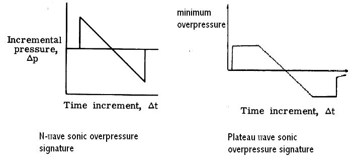
The sizing code used two numerical approximations for determining the sonic boom overpressurecreatedbytheaircraft.Twopaperswritten by Carlsonand Seebassoutlined numerical methods for approximating the sonic boom overpressure created by the aircraft. These numerical models were integrated into the sizing code and iterated for each aircraft configuration. The two numerical models were used in parallel because they each predicted a different type of sonicboomsignature.TheSeebassmethodpredictedthe plateau wave sonic boom signature, while the Carlson methodpredictedtheN wavesonicboomsignature.
Eachmethodrequireddifferentdatatopredictthesonic boom overpressure. Carlson required a cross sectional area distribution, while Seebass required basic aircraft dimensions including take off gross weight. From Seebassit was seen that for a supersonic aircraft, it would be more desirable to have a plateau wave rather than an N wave pressure distribution as it spreads the overpressure over a finite period of time. This would result in a lower average sonic boom overpressure and thus a smaller sonic boom signature. The objective of thisfunctionwastogivetheuseranideaonwhatkindof sonic boom overpressures the aircraft configuration would produce for these two boom signatures. This function completes that objective by using two different numericalmodelstopredicttheresultingpressurewave. A more detailed analysis of the methods used and the results from the sizing process is presented in the Sonic Boomsection.
The Aerofoil function takes in the geometry of the new wing and calculates the CL, max at take off and landing. The air foil used in the working model is NACA64A410. Itst/cis10%.
Thisisnecessaryforcalculatingthelandingandtake off fieldlengthsintheConstraintsfunction.Amoredetailed description on how this function works is outlined in Aerodynamicssection.
SELECTION:
1. Wavg =½(Wi +Wf )
Wi; aircraft initial weight at the beginning of the cruise
Wf;finalaircraftweightattheendofthecruise
2. Clc =
Clc;aircraftidealcruiseliftcoefficient
Vc;aircraftcruisespeed airdensityatcruisingaltitude S;wingplanformarea
3. Clcw
Clcw;wingcruiseliftcoefficient
4. Cli=
Cli;wingaerofoilidealliftcoefficient
5. Clmax =
VS=aircraftstallspeed
WTO =maximumtake offweight =airdensityatsealevel
6. Clmaxw =
Clmaxw ;wingmaximumliftcoefficient
7. Clmaxfrom=
Clmaxfrom; wing aerofoil gross maximum lift coefficient
8. Clmax =Clmaxfrom
Clmax;wingaerofoilnetmassliftcoefficient
9. Rootchord,Cr =
10. Tipchord,Ct =Cr *
LIFT COEFFICIENT:
It relates the angle of attack to the lift force. If the lift force is known at any specific airspeed, then, lift coefficientcanbedeterminedfromtheformula
CL =
Where, L;liftforce
;fluiddensity
S;surfacearea
To find lift coefficient value we refer NACA aerofoil series
CL, CD done in wind tunnel effect test “coefficient of lift (CL)Vs angleofattack“graph.
CL dependsRe,M,angleofattack.
International Research Journal of Engineering and Technology (IRJET) e-ISSN: 2395-0056
Volume: 09 Issue: 05 | May 2022 www.irjet.net p-ISSN: 2395-0072
Enginesplaysagreatrolewhenitcomestodesigningor accuratelysizeofanaircraft.Thisisprimarilyduetothe need for different fuel consumption data during the manydifferentpartsofthedesignmission.Varioussteps were identified when modelling of the Supersonic engines.
This in turn drives the engine selection to satisfy the level flight condition during cruise. Further, the amount of fuel required for the mission is dependent on how muchthrust isrequired, andtherefore dragcalculations have a great influence on the sizing process of the aircraft. Drag prediction is divided into three phases: subsonic,transonicandsupersonicflightregimes.These flightregimescorrespondtoMachnumbers1.6.
Insupersonictocomputeparasitedrag,sameequation as subsonic but form factors and interference factors ignored.
√ Where,
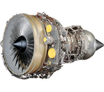
TheengineusedinthismodelisGeneralElectricCF34 8E turbofan engine of 14200pounds (62.28 KN) thrust each2engines.Maximumtake offbyis5394ft(16444m) andmaximumlandingis4072ft(1241m).
Tofindthetimeittakestotravelagivendistanceat agivenspeed,usingthefollowingequation Now, tofindtheaircraftfuelconsumption,wetake =4643.50litres
Therefore, the amount of fuel burned in an hour is 4643.50litres.
An accurate prediction of drag is essential to the design of the Supersonic aircraft. For steady level flight, a simple force balance reveals that the thrust that the aircraft must have is equal to the drag that acts on it.
Oneofthemajorcomponentsofdragariseduetoshock wave is wave drag. While there are NASA codes that predict wave drag, they require a very detached description of the aircraft geometry to work effectively. AsimplifiedarearulemethodologydevelopedbyJumper isusedinpredictingwavedrag. D= ∬ | |
The Aerofoil selection process for the Commercial Supersonic aircraft requires an in depth knowledge of aerofoil performance in supersonic, subsonic and transonicflight.Thewingistheprimarysourceofliftfor the aircraft and wing aerodynamics plays a vital role in deciding the aircraft flying qualities. Very little information was available on aerofoils suited for the required design mission. For this reason, a database of existingsupersonicaircraftalongwiththeaerofoilsthey used was created. Below table provide available informationon aerofoils used in supersonic commercial aircraft.Giventhepopularityofitsapplicationinmodern supersonic commercial aircraft, the NACA 6 series and the biconvex aerofoils stand out as the best options for therequireddesignmission.
Type of aerofoil
International Research Journal of Engineering and Technology (IRJET) e-ISSN: 2395-0056
Volume: 09 Issue: 05 | May 2022 www.irjet.net p-ISSN: 2395-0072
overpressure. A number of different technologies were employed to help reduce the sonic overpressure of this aircraft.
Fig5.a:NACA64A410Rootchordofanaerofoil
1. Blunt nose The blunt nose design on the Supersonic aircraft will create a bow shock in front of the aircraft which keeps the shock waves from coalescing under the aircraft. This coalescence of shockwaves is the reason for high sonic boom overpressures. They create N wave shock signatures as in the case of earlier supersonic aircraft. A blunt nose design will help bring the N wave shock signature to a plateauwavesignaturewithalowersonicoverpressure. Conversely, using a blunt nose increases the wave drag of the aircraft. Optimizing the aerodynamic shaping can reducethewavedragoftheaircraft.
Fig5.b:NACA64A410Tipchordofanaerofoil
To select the best aerofoil for use on the Commercial Supersonicaircraftare:
1.HighCLmaxasrequiredduringtake offandlanding. 2.Delayedstallangle.
5.1.2 Drag build-up
Oneofthemajorcomponentsofdragarisedue toshockwaveiswave drag. WhilethereareNASAcodes that predict wave drag, they require a very detached descriptionoftheaircraftgeometrytoworkeffectively.
AsimplifiedarearulemethodologydevelopedbyJumper isusedinpredictingwavedrag: D= ∫ ∫ | |
5.2
The 0.3 lbs./sq. ft overpressure limit is one of the primary reasons why supersonic aircraft are not in operation in the commercial market today. In order for the Supersonic aircraft to get its passengers to the destination fast, it has to surpass this upper limit on
Fig6:showsthedifferentsonicoverpressuresignatures discussed.
2.Dihedral angle – A dihedral angle on the lifting surface of the aircraft can reduce the sonic overpressureby making the area distributionsmoother, which has a high effect on the sonic overpressure signature. Also, a dihedral angle has the effect of increasingtheeffectivelengthoftheaircraft.
3.Low AR, high sweep A highaspectratio,lowsweep wing has the effect of increasing lift rapidly over the wing.ThisisanothermajorreasonforthecreationofN wave shaped sonic signature. A low aspect ratio, highly sweptwingbringstheaircraftsonicboomoverpressure signaturetothatofaplateauwave.
4.Smooth area distribution A smooth area distributionisvitaltoreducecreatingmultipleshocksat multiple locations on the aircraft. Smooth area distributioncoupledwiththebluntnosedesignwillhelp bringdownthechancesofmultipleshocksoriginatingall over the surface of the aircraft, which could coalesce togethertogiveahighsonicoverpressure.
Twodifferenttechniqueswereemployedtocalculatethe sonic overpressure on the aircraft. One technique was based on the “Simplified sonic boom prediction” paper
International Research Journal of Engineering and Technology (IRJET) e-ISSN: 2395-0056
Volume: 09 Issue: 05 | May 2022 www.irjet.net p-ISSN: 2395-0072

by Harry W. Carlson. The other method used was developed by R. Seebass and A.R. George in the paper titled “Sonic boom minimization”. While the Carlson methodmakesuseoftheareadistributionoftheaircraft todeterminetheshapefactoroftheaircraftandusethe shape factor to calculate the N wave overpressure signature, the Seebass method makes use of basic aircraftparameters(Weight,length,Machnumber,etc...) to determine the plateau overpressure signature of the aircraft.
SignatureDuration,Δt0.03s
Since the Carlson method was used to calculate the aircraft sonic overpressure based on the aircraft geometry, it is chosen as the more reliable of the two methods and is explained in more detail. The Carlson method was obtained from NASA Technical Paper 1122 titled “Simplified Sonic Boom Prediction”. Although this methodgivesaroughestimateofthesonicoverpressure and signature duration, much more research and analysisinsupersonicsonicboommitigationisrequired to develop the final aircraft design. The Carlson method involves three major steps to calculate the sonic boom overpressureanditstimesignature.
1 Determine Shape factor In order to calculate the shapefactoroftheaircraft,
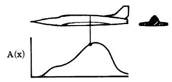
a.Generate axis normal cross-sectional area distribution The cross sectional area distribution alongthelengthoftheaircraftwasgeneratedbytheA/C Geometry function in the sizing code. Details about this process were discussed earlier in the aircraft geometry section.Thewireframearea
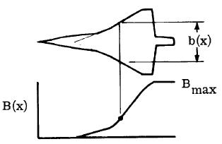
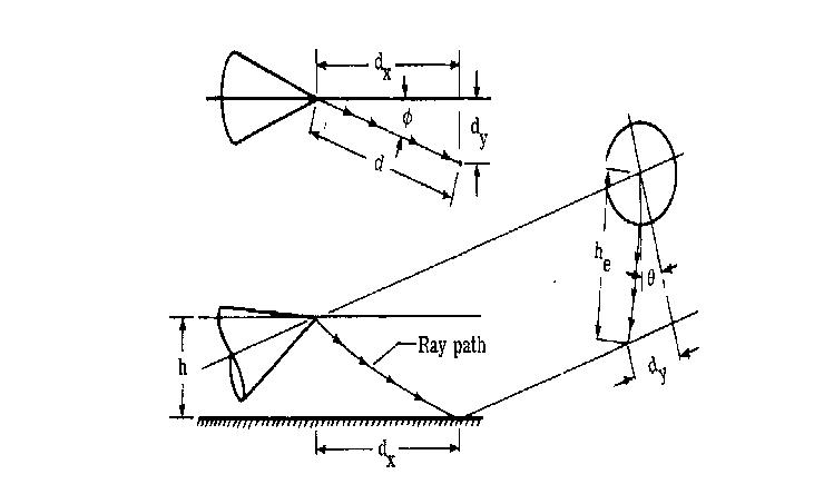
b.Equivalent area due to lift A reasonably accurate approximation of the equivalent area due to lift is calculatedfromthespandistributionalongthelengthof theaircraft.ThishasbeendescribedinFigure24,where b(x)isthespanwisedistributionalongthelengthofthe aircraft. This is used to calculate the equivalent area distribution,B(x).B(x)iscalculatedusingtheequation √ ∫
where M is the supersonic cruise Mach number of the aircraft, pv is the atmospheric pressure at vehicle altitude,Wistheweightoftheaircraft,Sistheplanform area, istheflightpathangle forsteady levelflight) and θ is the initial ray path angle if directly under flightpath)
Fig
c. Combined effective area The geometric area combined with the equivalent area due to lift gives the effective area. The combined effective area for the Supersonic aircraft is given in Figure. This distribution curve was smoothened to yield a better plot with lesser kinks.
International Research Journal of Engineering and Technology (IRJET) e-ISSN: 2395-0056
Volume: 09 Issue: 05 | May 2022 www.irjet.net p-ISSN: 2395-0072
Fig10:Shapefactorasafunctionofeffectivearea parameters
2. Calculate effect of atmosphere on propagation The effect of atmosphere on boom propagation needed to be calculated. This was done by determining the effective Mach number and effective altitude of supersoniccruise.TheeffectiveMachnumberisgivenby theformula(Carlson). Me = √ Where,
Fig11:cutoffMachnumber,Mc
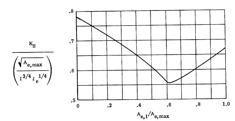
Thus, we find the formulae to calculate the Peak shock overpressureandtimesignatureare, =KPKR√ ⁄ ⁄ ⁄
Fig12:Ray PathdistancefactorKd
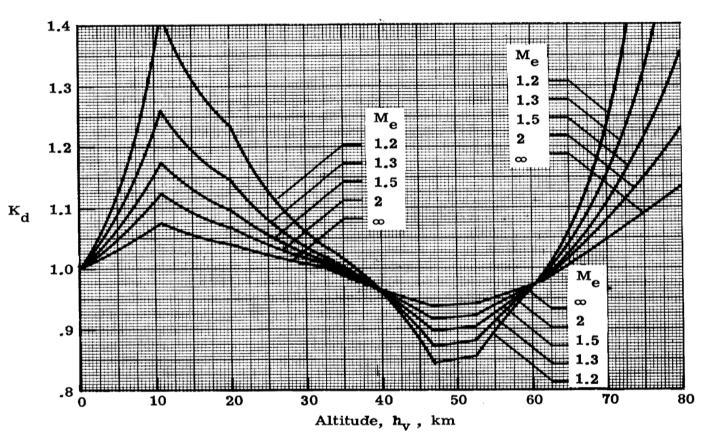
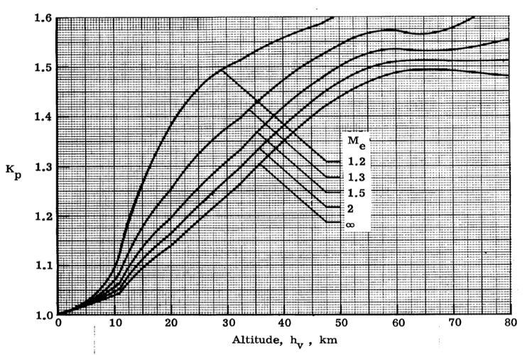
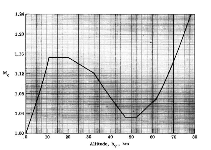
Fig13:Pressureamplificationfactor,kp
Volume: 09 Issue: 05 | May 2022 www.irjet.net p-ISSN: 2395-0072
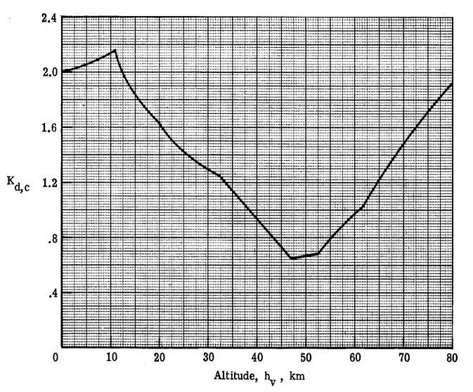
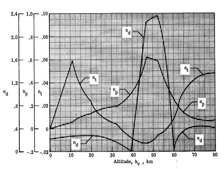
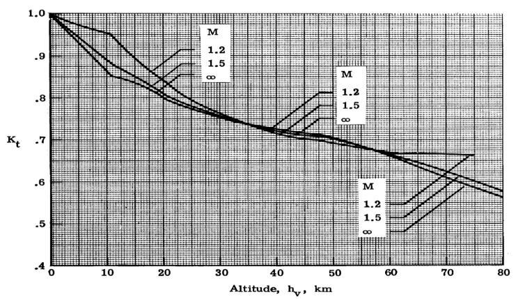
Fig14:Signaturedurationfactorkt Fig15:Atmosphericfactorcurvefitexponents
KL =0.000421 b. KS = 0.74√ =0.123 c. Me = √ =1.049 d. d = Kd (√ ) =12.529km e. √ =44.56degree f. dy= d Sin =12.529Sin44.56=8.791km g. he = √ =15.892km h.Kd =0.3 i.Kp =1.5 j.Kt =0.9
Fig16:Cut offraypathdistancefactork d,c
Usingtheaboveformulae,wecalculatetheoverpressure andtimesignatureoftheaircraftweget, a. KL = √ √
Now,substitutingallthevaluesweget, =KPKR√ =0.547psfor26.23Pa Also, ⁄ ⁄ ⁄ =0.3sec Hence,usingCarlsonwefoundcertainvalues
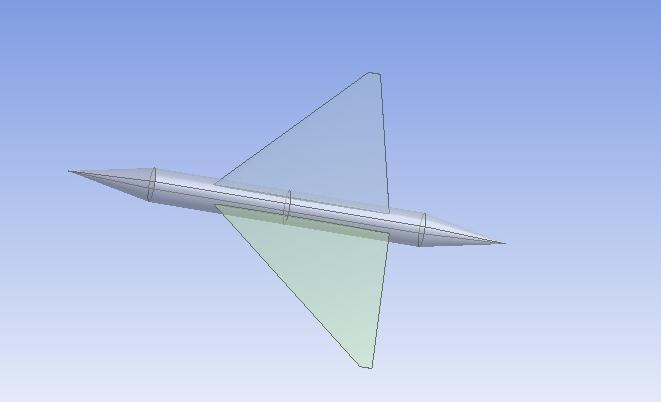
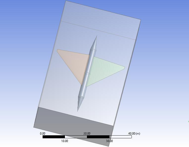
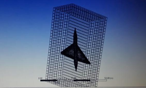
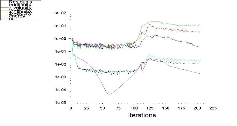
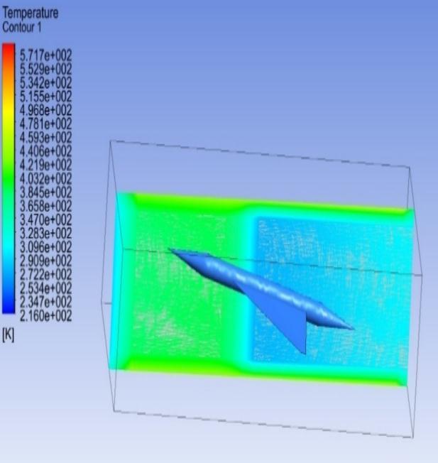
Fig23:Temperaturedistributionovertheaircraft
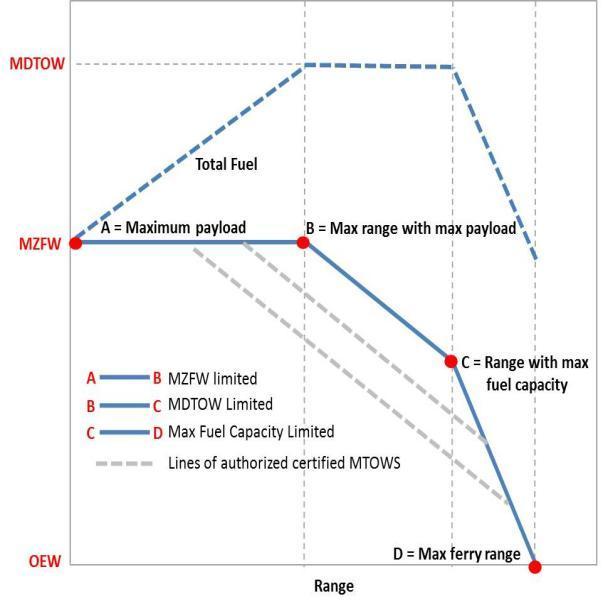
Creation of the range diagram provides an outline for cargo loading capability of the aircraft with correspondingrange.Thenumericalvalueswerederived from the Breguet’s range equation from the start of cruise to the end of cruise. The initial aircraft weight with fuel weight has to correspond to the mission statement at the beginning of cruise end of climb. The maximum zero range for this aircraft is the maximum cargo load. There is no horizontal steady range for the commercial Supersonic aircraft because of the aircraft’s fuel requirements. The Supersonic aircraft cannot reach its operational altitude with a cargo weight equal to the amount of fuel. The aircraft range at maximum take off weight is 30177.95 kg, with the maximum range of 4600km.Allrangespresentedarecruiserangesonly.
(b)
Fig24:PayloadandRangegraph
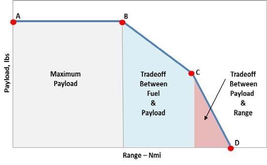
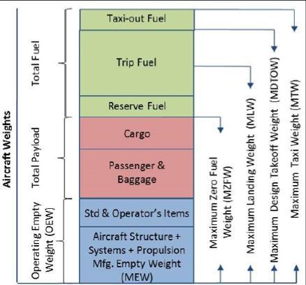
Fig25:Aircraftweightbuild up
Types of range are:
a. HarmonicRange
Rangewithmaximumpossiblepayload
b. FerryRange
Rangewithzeropayload,andincludingreservefuel
c. GrossStillAirRange
Range assuming all the mission fuel is utilized for cruiseflightalone.
(a)
6.1
The engine used in this model is General Electric CF34 8E turbofan engine of 14200pounds (62.28 KN) thrust
International Research Journal of Engineering and Technology (IRJET) e-ISSN: 2395-0056
Volume: 09 Issue: 05 | May 2022 www.irjet.net p-ISSN: 2395-0072
each2engines.Maximumtake offbyis5394ft(16444m) andmaximumlandingis4072ft(1241m).
Tofindthetimeittakestotravelagivendistanceat agivenspeed,usingthefollowingequation Now, tofindtheaircraftfuelconsumption,wetake =4643.50litres
Concorde was powered by four Rolls Royce/SNECMA Olympus 593 engines. This engine is the direct descendant of the Bristol Siddeley Olympus, the world’s first two spool axial flow turbojet engine, designed and built in Patchway. The Olympus 593 was flight tested from Filton Airfield fitted to the underside of a Vulcan bomber.
Therefore, the amount of fuel burned in an hour is 4643.50 litres. F34 8E is an advanced 14,500 pound thrust class turbofan propulsion system and a member of GE’s popular CF34engine family. It is the system that powers Embraer’s 7 90 passenger airliners, the EMBRAER 170/175. The 8E takes full advantage of its CF34 design and operational experience lineage as well as its relationship with other advanced CF34 models. It incorporates all of the service proven reliability, environmental and operational characteristics that have earned the CF34 engine family an excellent global reputation with airline and corporate operators for exceptional performance. The 8Epropulsionsystemincorporatesanacelledesign specifically tailored to the EMBRAER 170/175 underwing installation. The new design maximizes LRU accessibility,resultinginenhancedmaintainability
The engineering analysis although not satisfy all of the requirements of the aircraft but it’s close to those goals. Therefore, the concept of the supersonic commercial aircraft transport is definitely worth designing.
As, we calculated both numerically and computationally we see aerodynamic flow over the body is currently approximated and no shock interactions have been considered. Fuselage structures must be further researchedtoincludespecializedstructural loadpathat location of high stress concentration. CATIA model of fuel tanks, cargo space, centre of gravity travel i.e., aircraft load configuration must be allotted for more precisecalculation.Materialselectionshouldbeinputted intoCATIAprovidinga finalizedmomentsabout thex,y and z axis. The results from finalized CATIA model can be used to validate the dynamic stability and control of the aircraft. The results can provide a more accurate aircraft diagram as well mission performance. These results will provide insight on further feasibility of the Supersoniccommercialaircraft.
A simplified Carlson method for calculation of the overpressure and time signature characteristics in supersonic commercial aircraft configuration is calculatedandobservedintheCFDflow.The procedure donestepbystepreliesgreatlytothegreatextentonuse of the charts to provide the necessary sonic boom generation and propagation factors for use in relatively simple expressions for signature characteristics. With a bit inaccuracy in numerical complete calculations can often be obtained in less time than is required for the preparation of computer input data for the more accuratecalculationmethods.
International Research Journal of Engineering and Technology (IRJET) e-ISSN: 2395-0056
Volume: 09 Issue: 05 | May 2022 www.irjet.net p-ISSN: 2395-0072
We =EmptyWeight
R =Range
E =Endurance
KL =Liftparameter
W =Weightofanaircraft =flightpathangle
θ =raypathazimuthangle
ρv =atmosphericpressureataircraftaltitude
l =lengthofanaircraft
KS =aircraftshapefactor
Me =a/ceffectiveMachno.governingsonicboom atmospherepropagationcharacteristics
d =distancebetweena/cgroundtradepositionat timeof sonicboomgenerationandlocationofground impactpoint.
Kd =ray pathdistancefactor h =hv hg (altitudeofaircraftaboveground)
Φ =anglebetweena/cgroundtrackandground projectionof raypath.
dy =Componentofdinadirectionperpendicularto a/c groundtrack he =effectivealtitude
Kd =raypathdistancefactor
Kp =pressureamplificationfactor
Kt =signaturedurationfactor
ΔPmax =bowshockoverpressure
KR =reflectionfactor
ρg =atmosphericpressureatgroundlevel
Δt =signatureduration
MAC =MeanAerodynamicChord
1. Raymer, D.P., “Aircraft Design: A Conceptual Approach”, AIAAEducationSeries,FourthEdition
2. Harry W. Carlson, “Simplified Sonic-Boom Prediction,” NASATechnicalPaper1122,1978
3. “Near Field Sonic Boom Calculation of BenchmarkCases”ConferencePaperJanuary2015
4. “A Numerical Method for Blast Shock Wave Analysis of Missile Launch from Aircraft” http://dx.doi.org/10.1155/2015/897213 Sebastian Heimbs,JosefRitzer,andJohannesMarkmiller
5. “SOME EFFECTS OF WING PLANFORM ON SONIC BOOM” by Lynn W. Hunton, Raymond M. Hicks, und Joel P. Mendoxu Ames Research Centre Moffett Field,Cui$94035
6. “Sonic Boom and Drag Evaluation of SupersonicJetConcepts” ConferencePaper·June2018 DOI:10.2514/6.2018 3278
7. “Reducing Sonic Boom, A collective effort statusreport” byCharlesEtterandPeterG.Coen
8. “OPTIMUM SUPERSONIC CLIMB” NguyenX.vinh and Yih Feng University of Michigan, Ann Arbor,Michigan48109
9. “Current Research in Sonic Boom Minimization”,Darden, C. M. & Mack, R. journal ProceedingsoftheSCARConference.NASACP 001,held at Langley Research Centre, Hampton, Virginia, November 9 12, 1976, 1006 pages, produced by NASA, Washington,D.C.,1976,p.5251976NASCP...1.525D
10. “DesignofaLow Boom Supersonic Business Jet Using Evolutionary Algorithms and an Adaptive Unstructured Mesh Method” August 2004 DOI: 10.2514/6.2004 1758
11. http://www.concordesst.com 12. Explore the world of Concorde with Heritage Concorde”Concordewing” 13. Seebass, R. and George, A.R., “Sonic boom minimization” CornellUniversity,January1971 14. Gordon, “Concorde, Celebrating an Aviation Icon”, October,2006 15. Jumper, E. J., “Wave Drag Prediction Using a Simplified Supersonic Area Rule”, Journal of Aircraft, Vol.20,No.10,October1983,pp.893 895 16. SonicBoomsFS 2003 11 016DFRC 17. NACA64A410(naca64a410 il) 18. Cruise Flight Range and Endurance of Jet drivenAircraft. 19. “Design Guidelines for Supersonic Aircrafts inCivilAviation” TridibBanerjee 20. “Calculation of the Flight Characteristics of the Aircraft”, AN 225 Ahmed Soliman M. Sheriff NovosibirskStateTechnicalUniversity,Russia 21. “Introduction to flight” Raymer, D.P., AIAA ThirdEdition
© 2022, IRJET | Impact Factor value: 7.529 | ISO 9001:2008 Certified Journal | Page3285
International Research Journal of Engineering and Technology (IRJET) e-ISSN: 2395-0056
Volume: 09 Issue: 05 | May 2022 www.irjet.net p-ISSN: 2395-0072
23. “Multifidelity Design Optimization of Low Boom Supersonic Jets Journal of Aircraft “January 2008DOI:10.2514/1.28948
24. D. J. Maglieri, D. A. Hilton, and N. J. McLeod, “Experimentson theeffectsofatmospheric refraction and airplane accelerations on sonic boom ground pressurepatterns”,TND 3520,NASA,1966.
25.P. M. Gill and A. R. Seebass, “Non linear acoustic behaviour at a caustic: an approximate solution”, AIAA Progress in Astronautics and Aeronautics HJ.T. Nagamatsu(Ed.),MITP
Mr. Bijay Kumar Sah was born on 27th may 2001 and currently pursuing B.E Final year of Aeronautical Engineering. Had presented 5 papers at National and International Technical Symposium. My research interest includes Aero modelling (RC and UAV), Aerodynamics, Aircraft & Rocket propulsion, Aircraft Structure, Design and fabrication of Satellite, Fluid mechanics, Thermodynamics, Computational Fluid dynamics,CompositeMaterial,RocketandMissile
Contact:sahbijay2001@gmail.com

Ms. Keerthana Rathinavel wasborn on 11th June 2001 and currently pursuing B.E Final year of Aeronautical Engineering. My researchAreaincludesAerodynamics, Aircraft structure, Propulsion, Thermodynamics, Fluid Mechanics, AeroModelling(RC&UAV),andCFD.
Contact:keerthanarvel@gmail.com


Mr. Naveen kumar. M was born on 05 09 2000 and currently pursuing B.E Final year of Aeronautical Engineering. My research area includes in Drone Fabrication, Aerodynamics.

Mr. Ashir Azar was born on 16/03/2000 and currently pursuing B.E Aeronautical engineering. My research interest includes Aerodynamics, Propulsion, Drone fabrication.
Dr.S.P.Venkatesan was born on 4th November in 1976 has completed his Ph.D(Thermal Design)in Anna University,ChennaiTamil Nadu,India in the year July 2018 and M.E (Engineering Design)in the year 2000 from Kongu Engineering College,Perundurai,Tamil Nadu,India under Bharathiyar University,Coimbatore,Tamil Nadu,India and B. E (Mechanical Engineering) in the year 1999 Madras University,Chennai,TamilNadu,India.
Has got nearly14years of Teaching experience with Research experience of 6 years and Industrial experienceof 5years
Publishedmorethan35paperinInternationalJournalin varioustopicsinthefieldofMechanicalengineering
Contact:spvensphd@gmail.com