International Research Journal of Engineering and Technology (IRJET) e ISSN:2395 0056

Volume: 09 Issue: 05 | May 2022 www.irjet.net p ISSN:2395 0072
International Research Journal of Engineering and Technology (IRJET) e ISSN:2395 0056
Volume: 09 Issue: 05 | May 2022 www.irjet.net p ISSN:2395 0072
1PG Student, M. Tech IDC, Priyadarshini College of Engineering, Nagpur, Maharashtra, India.
2Associate Professor, Department of Electrical Engineering, Priyadarshini College of Engineering, Nagpur, Maharashtra, India. ***
Abstract This Project presents a Drive fed from hybrid dc micro grid system. Power is fed from renewable energy source and AC source. Proper Coordination between the PV source and Grid is required for smooth operation. In this paper, appropriate control technique is used for providing adequate control via power electronics interface. The DC DC boost converter is used on the PV side to attain the maximum power from the PV array. The Zeta controlling converter topologies used on the grid side which can help to co ordinate and meet the output result. DC AC voltage source converter is implemented to maintain the DC link voltage constant. The parameters are controlled in the synchronous reference frame PLL frame to make control easier. The Proposed system use for maintain continuity of supply, torque control smooth speedcontrol of motor and harmonics reduction
Key Words: Solar energy, photovoltaic array, DC DC converter, Zeta Converter. voltage source converter, grid, maximum power point tracking (MPPT), induction motor. Synchronous reference frame PLL, Zeta Converter.
Nowdays,tofulfilthesupplygrowthdemand weareon adopting more on the photovoltaic System (PV system). Photovoltaic are gaining popularity around the world as theirpriceDeclinesandefficiencyincreases.Definingthe hybrid system can be considered productive and gives uninterruptedpowersupplywhichhelpsinmaintainthe continuity of supply to share power to motor and managingtheloadonmotor.Thissystemiscombination of on grid solar system and have the ability to feed surplus electricity into main grid. But during power delivery some issues/ challenges are monitored of powerqualitywhichwillimpactboththeutilitygridand other connected load. Challenges can be seen are like: Solar is always varying or dynamic in nature. So, therefore voltage variations are hard to stabilize. The parameters considered are to be relating to multiple dimensional. A maximum power point tracking (MPPT) algorithm finds the ways of to the challenges gives maximum power for the operation of the PV system
during variations of solar irradiance and ambient temperature.Thismodelisprojectedforimplementation ofenergystoragethatcanprovidepowersupply,smooth out peak loads, smoothing of voltage and stand by generationincaseofgridfault.Dc dcconverterconverts input voltage into a desired dc link voltage for the collaborating data downstream 3 phase dc ac inverter. The output AC voltage in grid connected applications (photovoltaic systems) should be “constant” in terms of amplitude and frequency a power electronic interface is requiredtolinktheDCsourcewiththeloadandtomake the output AC voltage adequate in terms of frequency, amplitudeandphase.Inorderto achievemodellingand control of DC/AC converters are briefly presented in different reference frames (i.e., αβ and dq reference frames Developing algorithms for controlling drive using control strategies is used to achieve the desire performanceofthe motor
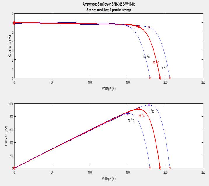
The photovoltaic process is "producing electricity directlyfromsunlight."Toincreasetheutilitynumberof PVcellareinterconnectedtogethercalledmodule.When modulesareconnectedinseries,theirvoltageisdoubled while the current stays constant and when modules are connected in parallel, their current is doubled while the voltage stays constant. To achieve the desired voltage and current, modules are wired in series and parallel into what is called a PV array.The Block Diagram of PV systemfedDrive(3phaseInductionMotor)showninfig 1consistingthe DC/DCconverter,VSIinverter, 3phase Induction Motor with the control strategy used SRF control is presented for voltage regulation, reactive power (var) compensation, and harmonic filtering Overall to study and analysis the drive (torque and speed).
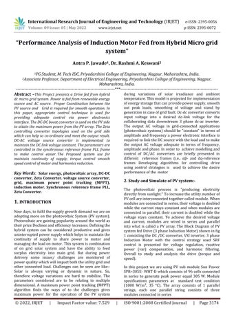
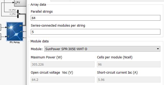
In this project we are using PV sub module Sun Power SPR=305E WHT D which consists of 96 cells connected in series to generate peak power equal 305 W. Module specifications parameters at standard test condition (1000 W/m², 35 °C) The array consists of 1 parallel strings, each one parallel string consists of three modulesconnectedinseries
(Induction Machine)
Fig 2: .MATLABSimulinkModelofPVfedDRIVE (InductionMachine) 2.1 SIMULATION RESULT OF PV SYSTEM: • Simulation results of the Matlab design of one singlePVarray.
• Referring from Fig 3 it can be observe that the maximum output power is giving near 1 kW at theoutputvoltageofapproximately200v.
• At the same time, the output current at output voltageof200visaround6amps.
The PV system is used to charge/discharge a battery bank with the MPPT algorithm. Maximum Power Point Tracking(MPPT)techniquesareusedtomaintainthePV array’s operating point at its maximum power point (MPP) and extract the maximum power available in PV arrays and to maximize the power generation of the PV system maximizes the output power of the load of the converter.
International Research Journal of Engineering and Technology (IRJET) e ISSN:2395 0056
Volume: 09 Issue: 05 | May 2022 www.irjet.net p ISSN:2395 0072
The hill climbing technique named as the shape of the power voltage (PV) curve. Sub techniques including Perturb and Observe algorithm (P&O) . Methods with P&O algorithms increase their effectiveness. The P&O algorithmdeliversthevalueofvoltageand currentfrom the solar photovoltaic array corresponding to the maximum power. A P&O method is the most simple, which moves the operating point toward the maximum powerpointperiodicallyincreasingordecreasingthePV arrayvoltage
In the Power Vs Voltage characteristic of a PV module showninWecanobservethatthereexistsinglemaxima i.e. a maximum power point associated with a specific voltage and current are supplied. The overall efficiency ofamoduleisverylowaround12%.Soitisnecessaryto operateitatthecrestpowerpointsothatthemaximum power can be provided to the load irrespective of continuously changing environmental conditions. This increased power makes it better for the use of the solar PV module. A DC/DC converter which is placed next to the PV module extracts maximum power by matching the impedance of the circuit to the impedance of the PV moduleandtransfersittotheload.Impedancematching can be done by varying the duty cycle of the switching elements.
The efficiency of solar panel is improved by Maximum Power Point Tracking (MPPT) when they set to operate at point of maximum power. There are different techniquesofMPPT.
Themostpopulartechniquesare: IncrementalConductancemethod, PerturbandObserve, Fuzzylogic, Neuralnetworks.
Weneedtoadjusttheinitialreferencevaluesindirection of increasing manner of output power and vice versa. Until photovoltaic array reach the maximum power points same process repeats. The characteristic power curveforaPVarrayisshowninFigure3.
If MPPT techniques considered it as a problem, then it finds the voltage VMP or current I and automatically under a given temperature and irradiance the PV array shouldgetthemaximumoutputpower.
MPPT algorithms are typically used in the controller designs for PV systems. The algorithms account for factors such as variable irradiance (sunlight) and temperature to ensure that the PV system generates maximumpoweratalltimes.
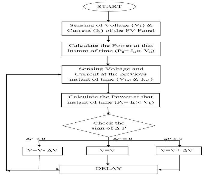
Fig-4: MPPTusingP&OAlgorithm
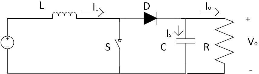
A boost converter is used to step up the PV voltage generatedtothesetdownvaluesothatitcouldmaintain withtheDClinkvoltagealongwiththeMaximumpower extractfromthePVmodule. Boostconvertertopologyis shown in Fig. 5 MOSFET/IGBT can be used as a switch. Boostconverteroutputisgivenas
As a voltage source PV system voltage is used in this system.Aboostinductor,tosupplyenergytotheoutput sidewheretheloadissupported,aninductorwillflipits voltage polarity to maintain current flow. MOSFETs,diodesandcapacitors
International Research Journal of Engineering and Technology (IRJET) e ISSN:2395 0056
Volume: 09 Issue: 05 | May 2022 www.irjet.net p ISSN:2395 0072
As the load drive used is the Induction motor which is the nonlinear load in which the current waveform does not take the shape of the applied voltage waveform and cannot describe the relation between voltage and currentwhichinturnproducesharmonicsandaffectthe powersystemcomponent.
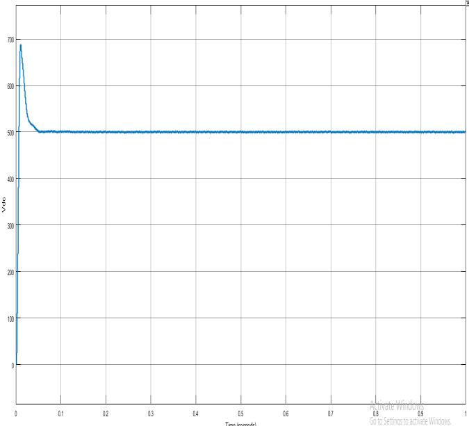
The boost converter is set to the voltage that will be constant for the stand alone time. Fig 6. Shows that the voltagehasbeenupto500Volts.
As Discussed in the section above in 2.1,2.2,2.3 the following result can be seen in the below characteristic ofmotorfedfromPVsystem,behavioragainst SpeedVS Time andTorqueVS Timethatbothsettlesat0.2sec
DC DC boost converter used operate the PV panel at maximumpowerpoint,andboosttheDCvoltagelevelto the appropriate level so that it is easily converted into the desired AC voltage. As PV voltage varies frequently , MPPT is used maximise the power to the appropriate vale as discussed above and boost converter provides the control of the PV panel output voltage , his will maintaintheinputvoltageoftheinverter.
ThePVSystemcanbeconnectedtothe3Phasegridviaa DC DC converter and a Voltage control Voltage Source Inverter(VSI)toconverttheDCVoltageto3phaseACas the Grid is a 3 phase AC Source. VSI are largely used because of its high efficiency, compact size and good controlonpowerflow.
It also provide Synchronization with the grid, Control of active and reactive power flow into the system , Control of DC link Voltage and harmonic reduction due to the converter connected can be helpful as the efficiency of theVSIishigh.
In this paper to transform, the grid voltage and current into 2 dimensional we have taken the help of abc to dq transformationSynchronousrotatingreferenceframe
The synchronous reference frame theory performs the operationinsteady stateortransientstateaswellasfor generic voltage and current waveforms. It allows controlling the active power filters in real time system. ThebasicfunctionofthePLListomeasure
Phase angle (ϴ) from the angular frequency (ω) of the gridVoltage.IntheSRFPLLthevoltagesofthe
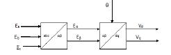
3 phasesoftheGrid(Ea,Eb,Ec)whichareseparatedin phase by an angle of 120 degree from each other are converted into dq reference frame in a two stage transformation process i.e abc frame to αβ reference frame to dq reference frame The transformation block diagramisshowninfig7.
TheThreephasevoltagesofthegridisgiveninequation (1)
Ea=Emcosωgridt
Eb=Emcos(ωgridt 2π/3) (1)
Ec=Emcos(ωgridt+2π/3)
Whereωgridt=Ɵgrid
ApplingtheClarkTransformation(abc→αβ Transformation)wegetequation(2).
[ ]= [ ][ ] (2)
SubstitutingthevaluesofEa,Eb,andEcinequation (2)wegetequation(3)asfollows.
International Research Journal of Engineering and Technology (IRJET) e ISSN:2395 0056
Volume: 09 Issue: 05 | May 2022 www.irjet.net p ISSN:2395 0072
sϴ(s)=C(s)Em(ϴgrid(s) ϴ(s)) (10)
(3)
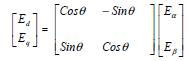
Appling the Parks Transformation (αβ →dq Transformation)wegetequation(4). (4)
Here the αβ is the stationary two dimensional reference frameandthedqisthetwodimensionalreferenceframe rotatingwithsomeangular velocity. Toachieve theGrid synchronizationwewillhavetosynchronizetherotation of the dq axis to that of the three phase voltages of the gridwhicharerotationatanangularspeedofωgrid.
SimplifyingtheParkstransformationwegetequation (5).
Ed=EmCos(ϴgrid ϴ)
Eq=EmSin(ϴgrid ϴ) (5)
To achieve grid synchronization the ϴ must be equal to ϴgridandtherebyequalizingtheinverteroutputvoltage frequency and phase with that of the grid voltage. So if ϴgrid=ϴthen
Ed=EmandEq=0. (6)
Butitifaverysmallerrorpersistsi.eif(ϴgrid ϴ)isvery smallandnearlyequaltozerothen
Sin(ϴgrid ϴ)=(ϴgrid ϴ) (7)
SoEq=Em(ϴgrid ϴ) (8) Sowecangettheangularfrequencyasgiveninequation (9).
ω= =CEq (9)
WhereCisthetransferfunctionofthePIcontroller. Hencebydesigningthepropercontrollerwecan successfullytrackthegridutilityFrequency(ωgrid) andphase(ϴgrid).
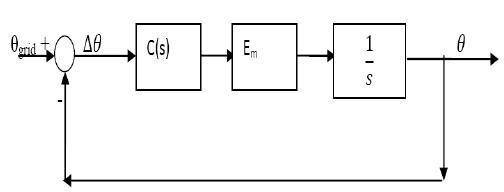
TakingtheLaplacetransformationofequation(9) wegetequation(10).
RepresentingthisexpressioninBlockDiagramform wegetfig8.
Fig 8: .LinearizedmodelofthePLL
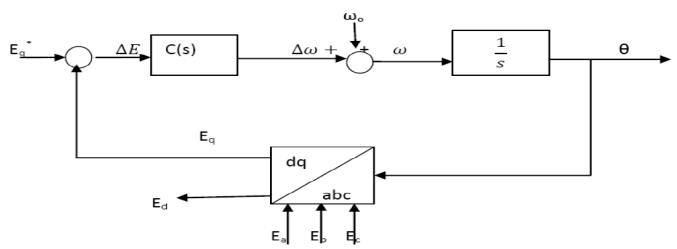
From the above equation we can see that for grid Synchronization Eq must be set to Zero. Doing this we get the overall PLL control structure as given in the following block diagram in Fig 9. Here ω o is the fundamental frequency of the grid in rad/s. Here Eq* is thereferencesetpointvoltageofEq.
Fig-9: OverallPLLcontrolstructure.
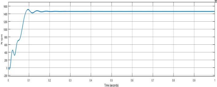
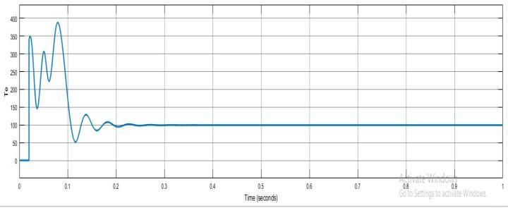
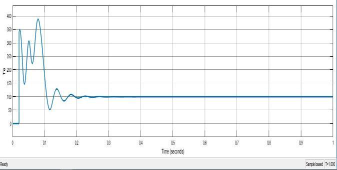
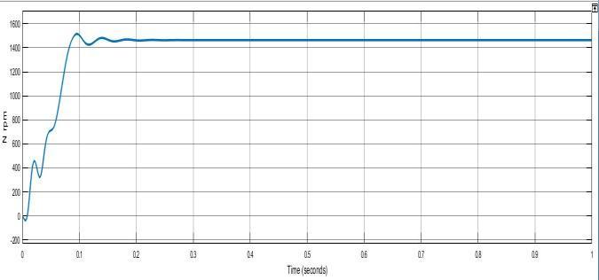
The modeling of the relevant system in Simulink is presented in fig 2. As discussed in above sections the components connected are used to achieve uninterruptedsmoothoperationofthedrive.Inthefig9 shows the characteristics of speed vs time and toque vs time.. As per the calculations and the observation the resultcanbeseeninthecharacteristicsshowing:
Speedof1460RPMsettleat0.2sec.and Torqueof 98N/m2 settleat0.2sec.
Whichwillhelppersistingtheefficiencyofthemotor.
International Research Journal of Engineering and Technology (IRJET) e ISSN:2395 0056
Volume: 09 Issue: 05 | May 2022 www.irjet.net p ISSN:2395 0072
Fig-9: SpeedVSTime andTorqueVSTimeModelofPV fedDRIVE(InductionMachine)
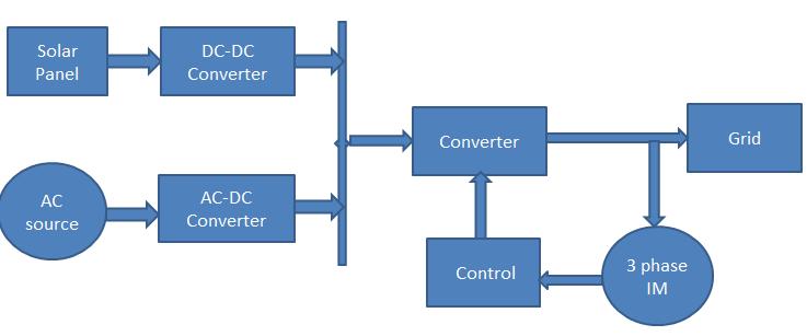
PV system connected in parallel with Other AC source whichisconvertedintoDC byusingZeta converterand formed DC grid output of DC grid fed input to the inverter which converted to AC and Fed to Induction motor for their operation .In case of no or less output From PV system continuity can be maintained by anothersystem
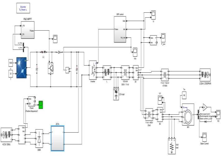
Fig 11: Simulationmodelofthehybridmicrogrid fedmotor
TheThreephaseoutputofthegridisconvertedtoripple DC by the use of DBR (Diode bridge rectifier). The convertedDCvoltageisfedtoZETAconverterwhichisa DC DC converter, making the rippled DC to constant DC withtheuseofabuckinductor.
The MOSFET switch provide in the ZETA converter switches according to the duty ratio given by the PI controller for which the input is given from the error value of the reference and measured output DC value of theZETAconverter.Itaclosedloopcontrol systemwith feedback PI controller circuit and the switching frequencyoftheZETAconverteris45kHz.
TheconvertedDCvoltageformtheZETAconverterisfed to the DC bus where PV model connected output of DC gridmaintainedtoconstantvalueof500V.
Inverted output is fed to motor and speed. Torque and Stator current parameter with closed loop controlled monitoredforfullloadtorque.
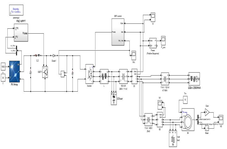
AC motors are widely used motors in all applications these days due to low cost, robustness, reliability and low maintenance. It is advisable to have Solar panels which deliver a power almost 2 to 3 times the rating of themotor.
Fig-10: Blockdiagramoftheoverallsystem
The rating of Induction motor used in this project is specified below in the table for suitable operation for which is to be controlled and provide a smooth operation
International Research Journal of Engineering and Technology (IRJET) e ISSN:2395 0056
Volume: 09 Issue: 05 | May 2022 www.irjet.net p ISSN:2395 0072
when added with hybrid system, that stables at 0.2 sec for Speed 1460 RPM and Torque 98N/m2 . With the control strategy using SRF and Zeta converter topology which That was needed to get co ordinated same stable supply workingstandalone without disturbingtheother systemachievingthesmoothspeedandtorque reducing the burden, harmonics, appropriate control methods of the motor, with suitable architecture and so achieved with this model. And remaining extra power generated canbeforwardedtothegrid.
Simulation model of the hybrid micro grid fed motor is presented in the fig 11, which shows the co ordination with the PV system switches automatically to AC supply when it reaches below the setup voltage, converting AC/DC using zeta converter giving good result and maintainedasconstantvoltagethatlinksproperwithDC linkamongtheotherconvertingtopology
[1] Khlaq Hussain, Bhim Singh, KamalAl Haddad "GIBasedControlSchemeforSingleStageGridInterfaced SECSforPowerQualityImprovement“IEEETransactions on Industry Applications( Volume:55, Issue:1,JanFeb.2019)
[2] KamranZeb, WaqarUddin, MuhammadAdilKhan, ZunaibAli, Muhammad UmairAli, NicholasChristofides, H.J.Kim, A comprehensive review on inverter topologies and control strategies for grid connected photovoltaic systemVolume94,October2018
[3] Farzam Nejabatkhah; YunWeiLi "Overview of Power Management Strategies Of Hybrid AC/DC Microgrid“ IEEE Transactionson Power ElectronicsYear:2015Volume:30,Issue:12JournalArticle
[4]AhmedElmelegi,EmadM.AHMED“StudyofDifferent PV Systems Configurations Case Study: Aswan Utility Company “17th International Middle East Power Systems Conference, Mansoura University, Egypt, December15 17,2015
[5]ShantanuChatterjee;SaibalChatterjee“Simulationof Synchronous Reference Frame PLL based Grid Connected Inverter for Photovoltaic Application” 2015 1st Conference on Power, Dielectric and Energy Management at NERIST (ICPDEN) ISSN:7084493 Jan. 2015
6] J. Svensson, “Synchronization Methods for Grid connected Voltage Source Converters,” in Proc. IEE Gener.Transm.Distrib.,vol.148,no.3,pp.229 235,May 2001.
Fig 12: SpeedVSTime andTorqueVSTime characteristicof hybridmicrogridfedmotor
ThesimulationresultofthePVSystemfedtotheIMwas takinga settling timeof0.2 sec fortheSpeed1460RPM andTorque98N/m2 ,WiththecontrolstrategyusingSRF and DC DC boost converter topology converter topology Whereas the time taken to perform IM was the same
[7] Kamran Zebab, Waqar Uddina, Muhammad Adil Khana, Zunaib Ali “A Comprehensive review on Inverter Topologies and Control Strategies for Grid Connected Photovoltaic System Renewable and Sustainable Energy Reviews”,Volume94,October2018,Pages1120 1141
[8] H. N. Zainuddin and S. Mekhilef, “Comparison of Maximum Power Point Tracker Techniques for PV System", 14th International Middle East Power System
Conference (MEPCON'10), Cairo University, Egypt. 2010,pp.750 755,Dec19 21,2010.
[9] K. O. Vijay and P. Sriramalakshmi, “Comparison between Zeta Converter and Boost Converter using Sliding Mode Controller,” International Journal of Engineering Research and Technology (IJERT), vol. 05, Jul2016
[9] K. O. Vijay and P. Sriramalakshmi, “Comparison between Zeta Converter and Boost Converter using Sliding Mode Controller,” International Journal of Engineering Research and Technology (IJERT), vol. 05, Jul2016
[10] M. Depenbrock “Direct self control (DSC) of inverter fed induction machine” IEEE Transactions on PowerElectronics(Volume:3,Issue:4,Oct.1988)
[11] Yuvraj Praveen Soni , Priyanka Paliwal , Mukesh Kirar “Control and Coordination of grid connected PV Fed Induction Motor” Proceedings of the International Conference on Advances in Electronics, Electrical & ComputationalIntelligence(ICAEEC)2019
International Research Journal of Engineering and Technology (IRJET) e ISSN:2395 0056 Volume: 09 Issue: 05 | May 2022 www.irjet.net p ISSN:2395 0072 © 2022, IRJET | Impact Factor value: 7.529 | ISO 9001:2008 Certified Journal | Page3181