
Design of FLC based Control Strategy for DSTATCOM for Power Quality Improvement with Balanced and Unbalanced Non-Linear Loads
Arati1 , Dr. G. V. Jayaramaiah2
1 PG Student, Dept. of Electrical and Electronics, Dr. Ambedkar Institute of Technology, Bengaluru, India
2 Professor & HOD, Dept. of Electrical and Electronics, Dr. Ambedkar Institute of Technology, Bengaluru, India. ***
Abstract In this paper, a distribution static compensator (DSTATCOM) is introduced to reduce the issues related to power quality in an electrical network. The energy source connected to the DSTATCOM device injects the real power in the system and also reduces the effects of non linear and unbalanced loads presented in the given system. The Proportional Integral (PI) controller in the control circuit is replaced with Fuzzy Logic Controller (FLC) and the performance of the electrical network under the PI and FLC are compared and presented. The proposed system is designed as well as simulated in MATLAB/Simulink software.
Key Words: Distribution static compensator, Real and Reactive power injection, Unbalanced load, PI control, FLC control, Harmonic Reduction.
1. INTRODUCTION
Themajoroccurringissueintheelectricalnetworkisvoltagesag(reductionin RMSvoltageoccursforashortdurationof 10ms to 60s). The reduction in the magnitude of voltage ranges from 10% to 90% of the rated voltage of the system. It occurs mainly due to utility fault, fault at consumer end or sudden increase in load demand. In utility fault, due to short circuit,thereisreductioninsystemvoltageashighcurrentstartsflowingduringthefaulttimeperiod.Theconsumerend fault is due to the fault in the equipment, non linearity in loads, etc. Lightning is also one of the major causes for the occurrence of faults in transmission lines. If these faults occurred continuously, it causes major disadvantage in terms of serviceandalsocauseseconomiclossesfromrepetitivemaintenance,poweroutagesandduetothereplacementoffaulty equipment etc. Voltage sag is the major occurring issue in the Power Quality among many others. There are no fixed solutions to mitigate this voltage sag occurrence but there are various methodologies presented so for compensation of thefaults byinjecting reactiveaswell asreal powersuchas FACTSdevices,capacitor banks, introducingDG unitstothe system,etc.
TheDynamicVoltageRestorer(DVR)andDSTATCOMarethemostefficientdevicesforcompensatingsuchpowerquality problems.ThecontrolstructuresorstrategiesarebasedonvariouscontrollersindealingwithsuchissueslikePI,PID,FLC, PRcontrollers.Inthis,PIcontrollersisoneofthebasiccontrollerswhichcanbedesignedtoinjectrealandreactivepower basedonsystemparameterssuchasFrequency,DCVoltage,ACVoltageetc.ButitisdifficulttodesignthePIcontrollerfor wide range of fault types and it is slower in response under transient conditions. Proportional Integral Derivative (PID) controller provides better response than that of PI controller but still it is inefficient to compensate the harmonic conditions. Proportional Resonant (PR) controller is suitable for harmonic reductions but in other issues such as short circuit faults, the performance is still needed to be improved. Hybrid controllers such as PI with PR or PID with PR are proposedandthecomplexityindesignisincreased.
In this paper, an indirect approach of current control is used to control the Voltage Source Converter (VSC) which combined with energy source formulates the DSTATCOM. The proposed system is tested under linear/non linear loads and balanced/unbalanced load conditions. The ability of Power Factor Correction (PFC), Load Balancing and Harmonic Reductionoftheproposed deviceis checked TheFLCreplacesthepresentPIcontrollerinthe DCvoltagecontrolloopof DSTATCOMandthesimulationresultsarecompared.
2. HYBRID RENEWABLE ENERGY SOURCES BASED MICROGRID WITH BATERRY ENERGY STORAGE SYSTEM.
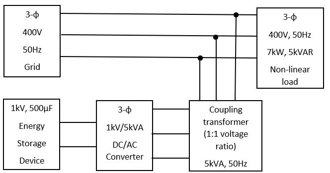
The proposed system is shown in figure 1, comprises of a VSC, a DC source, a coupling transformer in parallel to the distributionnetwork.Thethree phasegridsupplyingthepowerwith400V,50Hzisasfollows.

International Research Journal of Engineering and Technology (IRJET) e ISSN:2395 0056
Volume: 09 Issue: 05 | May 2022 www.irjet.net p ISSN:2395 0072
Fig1DistributionsystemwithDSTATCOM
Thevoltageandcurrentequationsforthethree phasegridisasfollows: [ ] [
( ) ( ) ( )] [ ] [
TheVSCinjectsreactivepowertotheload.
ThefunctionsoftheDSTATCOMareprovidedbelow:
1.Regulationofloadvoltageandinjectionofrealandreactivepower.
2.PowerFactorCorrectionand
3.Harmoniccurrentreduction.
Therelationforinjectedcurrent isprovidedbelow, ( )
TheinjectedapparentpowerbyD STATCOMisprovidedbelow,
( ) ( ) ( )]
The voltage is regulated by injecting the reactive power with the injected current is in quadrature with load voltage and the load regulation can also be done by injecting both real and reactive power in the system with minimum injected current.
International Research Journal of Engineering and Technology (IRJET) e ISSN:2395 0056
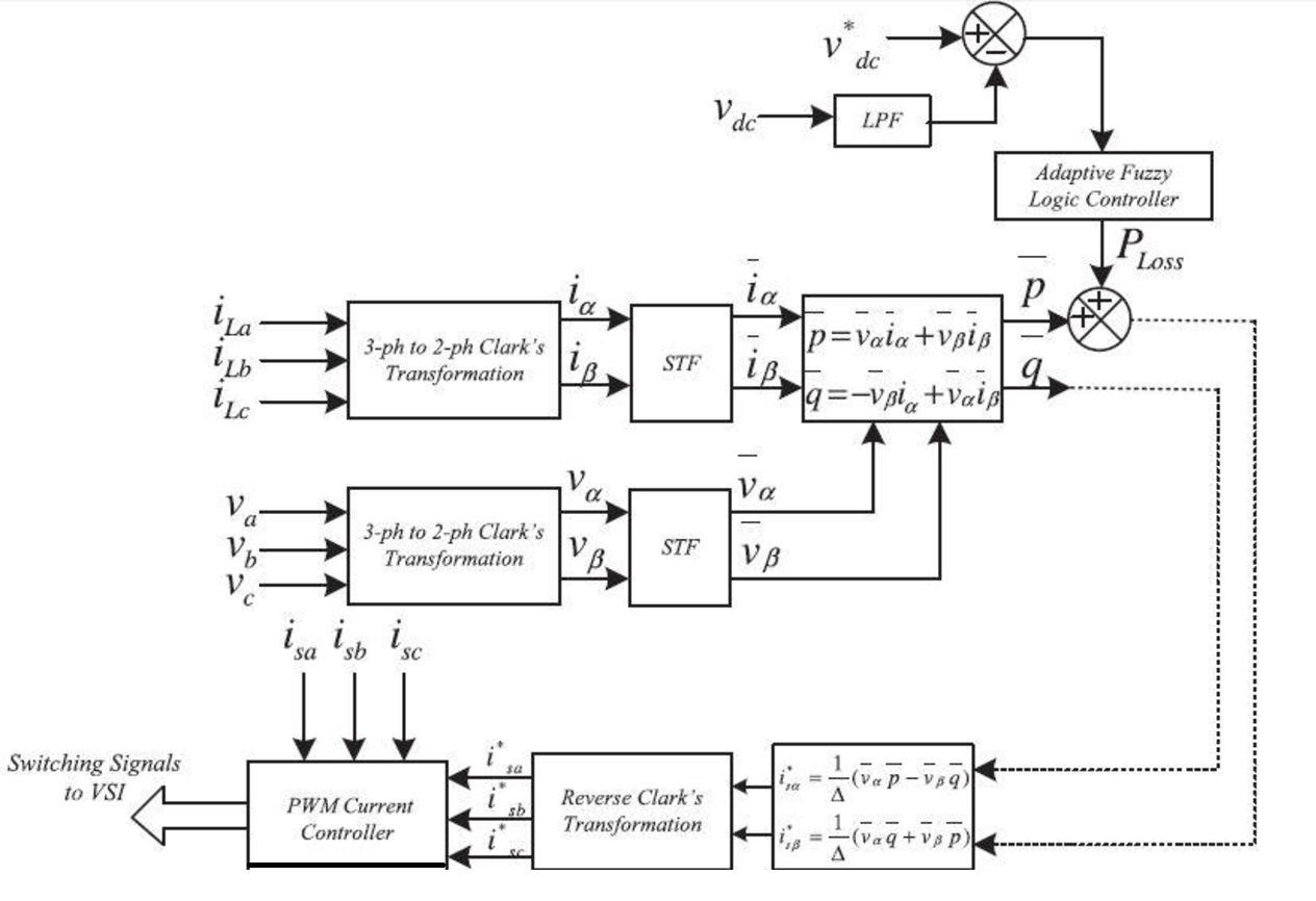
Thecontrolstrategyisasrepresentedinthefigure2
Fig2ControlstrategyofDSTATCOM
TheDCvoltagecontrollerovertheaveragevalueofDCbusvoltageoftheDSTATCOM( )andreferenceDCvoltage( ) provides real power loss which will be added with measured power and it is combined with quadrature axes. The resultant reference current is compared with measured current and passed through hysteresis control. The hysteresis currentcontrollergeneratesthepulsesforDSTATCOM.
3. DESIGN OF RLC FILTERS:
InRLCcircuit,thefunctionofRistoreducetheripplespresentinthecurrentwaveforms.Here1%ofloadcurrentistaken asripplelimitandR=ΔI/I=0.01Ω.
Theinductorvalueiscalculatedas
WhereFciscriticalfrequencyforharmoniclimits(100Hz)(belowthirdorderharmonicfrequency).
Thecapacitorvalueiscalculatedas
4. DESIGN OF FL CONTROLLER
Fuzzyinterferencesystem,themaincomponentoffuzzylogicsystemservesindecisionmaking.Thefunctionaldiagramof fuzzylogiccontrollerisasshowninthefigure3.
Volume: 09 Issue: 05 | May 2022 www.irjet.net p ISSN:2395 0072 © 2022, IRJET | Impact Factor value: 7.529 | ISO 9001:2008 Certified Journal | Page2368
International Research Journal of Engineering and Technology (IRJET) e ISSN:2395 0056
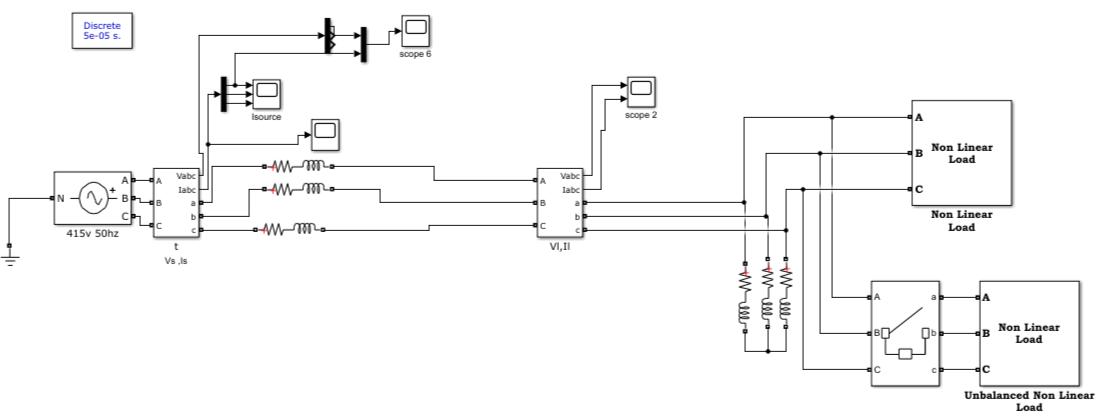
Fig3FunctionalblockdiagramofFuzzyLogicController
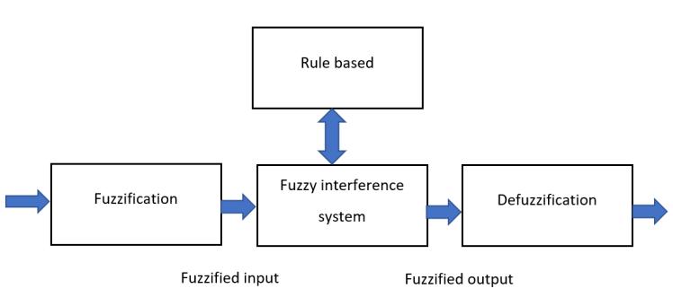
Fuzzyinferencesystemprocesscomprisesoffollowingprocedures: InputvariablesareprocessedandundergoestheFuzzificationstep Applyingthefuzzyoperator(ANDorOR)processaspertherules.
Defuzzificationofthefuzzyoutputs
TherulesprovidedfortheFLcontrollerisprovidedinTableIasshownbelow:
Table1.FLCruletable
Enables Output
PositiveSmall(PS)
NegativeVeryLow(NVL)
NegativeLow(NL) PositiveSmall(PS) NegativeMedium(NM) PositiveSmall(PS) NegativeSmall(NS) PositiveSmall(PS)
Zero PositiveMedium(PM) PositiveSmall(PS) PositiveMedium(PM) PositiveMedium(PM) PositiveMedium(PM) PositiveLow(PL) PositiveLow(PL) PositiveVeryLow(PVL) PositiveVeryLow(PVL)
5. SIMULATION SETUP AND RESULTS
Thesimulationcircuitforthebasesystemisprovidedinfigure4:
Fig4SimulationcircuitofDistributionnetworkwithoutDSTATCOM
Volume: 09 Issue: 05 | May 2022 www.irjet.net p ISSN:2395 0072 © 2022, IRJET | Impact Factor value: 7.529 | ISO 9001:2008 Certified Journal | Page
International Research Journal of Engineering and Technology (IRJET) e ISSN:2395 0056
Volume: 09 Issue: 05 | May 2022 www.irjet.net p ISSN:2395 0072
In this three phase voltage supply of 415V, 50Hz is providing power to the loads connected (both linear and non linear loads).Anunbalancedloadisconnectedtothesystematt=0.6s.
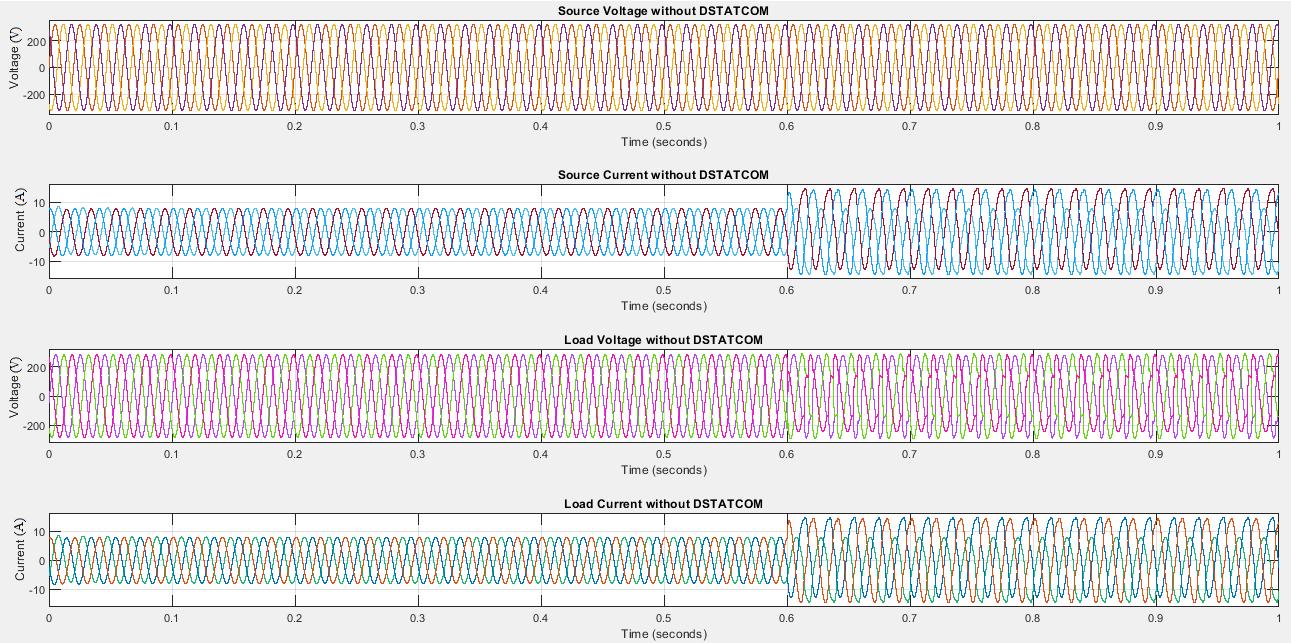
The load voltage and current waveforms without DSTATCOM are provided in figure 5 along with the source voltage and current
Fig5.LoadvoltageandcurrentwithoutDSTATCOM
Thevoltageisaround300Vandthecurrentisaround10Ainitiallyandwhen theunbalancedloadisconnectedatt=0.6s, theunbalancedcurrentincreasesto20A.
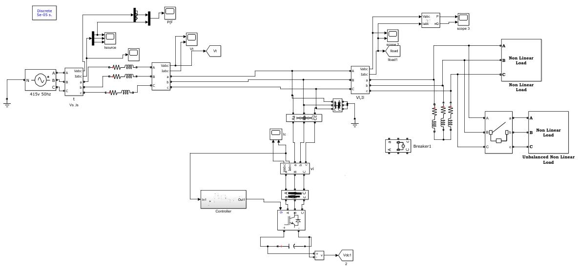
ThesimulationcircuitofthebasesystemwithDSTATCOMisprovidedinfig6:
Fig6SimulationcircuitofDistributionnetworkwithDSTATCOM
In this, the DSTATCOM is connected to the base system through coupling transformer of power 5000VA, voltage of 450V/450V.AnRLCfilterisalsoconnectedinbetweenthePointofCommonCoupling(PCC)andVoltageSourceConverter (VSC)device.
International Research Journal of Engineering and Technology (IRJET) e ISSN:2395 0056
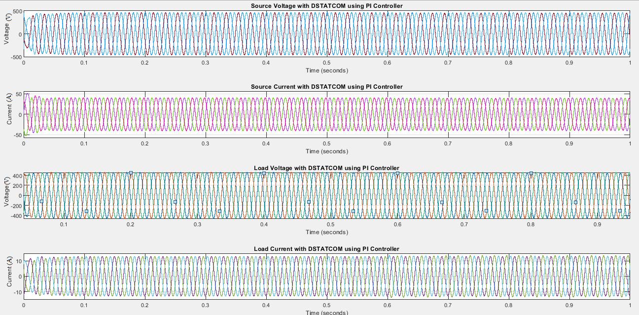
ThesupplyvoltageandcurrentoftheproposedsystemwithPIcontrollerisprovidedbelowinfigure7alongwiththeload voltage and current waveform. In this, the source voltage is around 440V and source current is around 40A. The load voltageisaround 460Vand load currentisaround13A.Here,unlikethe basesystem,thereisnounbalancebetweenthe phaseseventhoughtheunbalancedloadisconnected.
Fig7 WaveformsforsourcevoltageandcurrentalongwithloadvoltageandcurrentwithDSTATCOMusingPIController
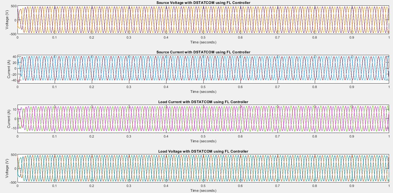
ThefuzzycontrollerreplacesthePIcontrollerin DCvoltagecontrolloopsothattheoverallperformanceofthesystemis improved.SimilartothePIController,thesourcevoltageisalsoaround440Vandsourcecurrentisaround40A.Theload voltage is around 460V and load current is also around 13A. Here too, unlike the base system, there is no unbalance betweenthephaseseventhoughtheunbalancedloadisconnected.Thewaveformsareasshowninthefigure8.
Fig8.WaveformsforsourcevoltageandcurrentalongwithloadvoltageandcurrentwithDSTATCOMusingFLController
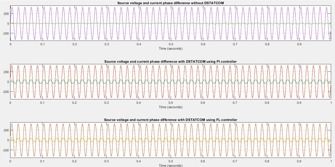
The difference in phase angle between voltage and current is 48.6 degrees (0.0027s in terms of time period) in the base systemwithoutDSTATCOM.Onusing thePIcontroller,thedifferenceinphaseanglebetweenvoltageandcurrentiszero degrees (0s in terms of time period) i.e., both voltage and current are in phase with each other. Similar waveforms are observedwhenFLcontrollerisusedintheDSTATCOM.Thiscanbeseeninthefigure9.
Volume: 09 Issue: 05 | May 2022 www.irjet.net p ISSN:2395 0072 © 2022, IRJET | Impact Factor value: 7.529 | ISO 9001:2008 Certified Journal | Page2371
International Research Journal of Engineering and Technology (IRJET) e ISSN:2395 0056
Volume: 09 Issue: 05 | May 2022 www.irjet.net p ISSN:2395 0072
Fig9Phasedifferencebetweenvoltageandcurrent
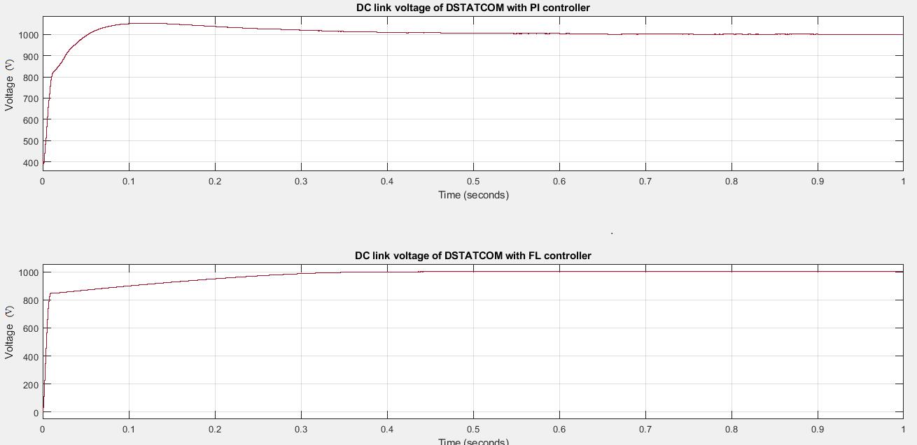
The DC link voltage of DSTATCOM is provided in Fig 10 For both the PI controller as well as FL controller, the DC link voltage is around 1KV as the reference dc voltage is provided as 1KV. Here the overshoots in FL controller are removed comparedtoPIcontrollerwherethepeakovershootisaround1053V.
Fig10DClinkvoltageofDSTATCOMusingPIcontrollerandFLcontroller
Therealpowerisaround6.8KWandreactivepowerisaround5.8KVARwhenDSTATCOMusingPIcontrollerisemployed. Therealpowerisaround6.9KWandreactivepowerisaround5.7KVARwhenDSTATCOMusingFLcontrollerisused Due totheunbalancedloadconnectedatt=0.6s,thereareripplespresentinbothrealandreactivepowerforDSTATCOMusing PIcontrolleraswellasFLcontroller.
International Research Journal of Engineering and Technology (IRJET) e ISSN:2395 0056
Volume: 09 Issue: 05 | May 2022 www.irjet.net p ISSN:2395 0072
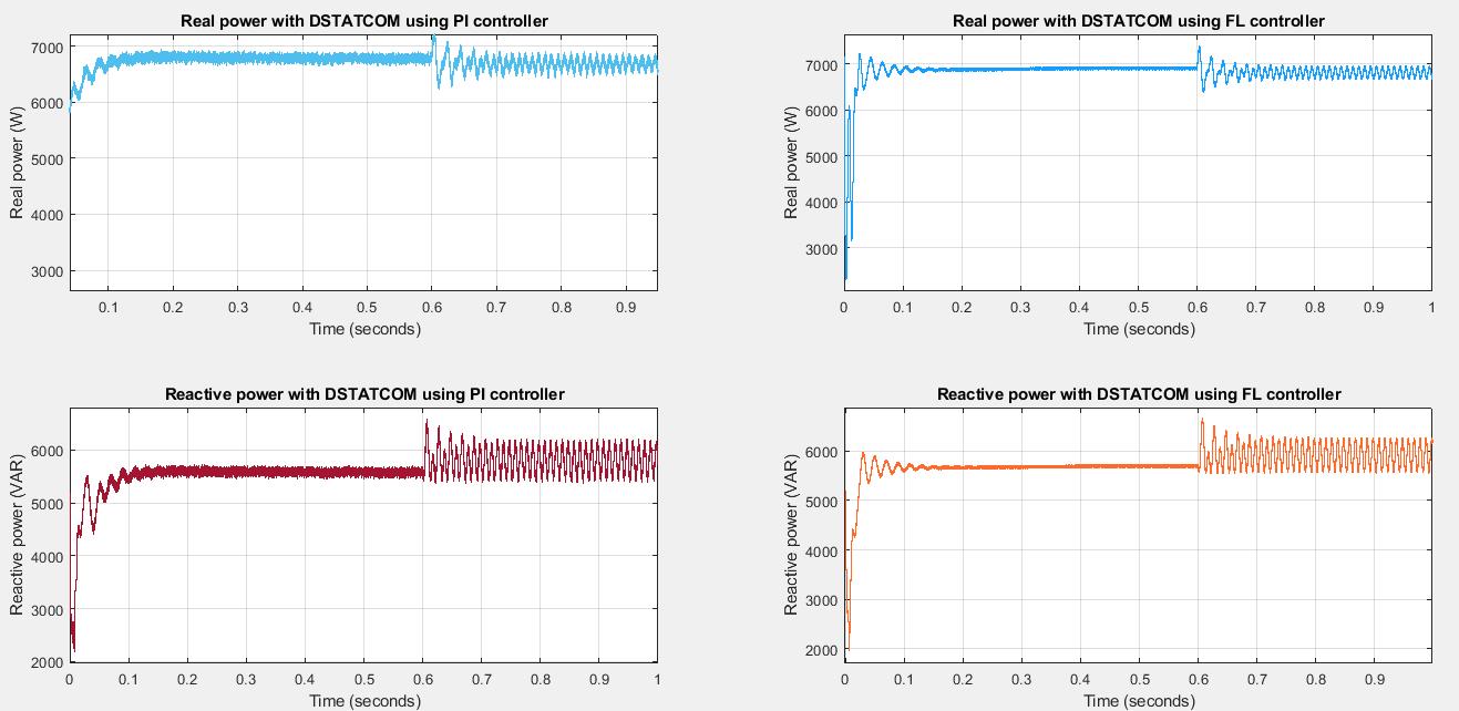
Fig11RealandReactivepowerwithDSTATCOMusingbothPIandFLcontroller
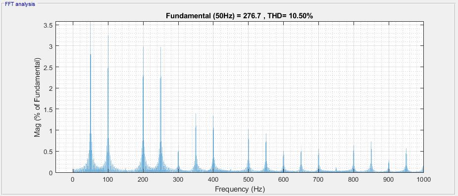
The%TotalHarmonicDistortion(THD)ofloadcurrentinthebasesystemisaround10.50%asdepictedinfigure12.
Fig12%THDofLoadcurrentwithoutDSTATCOM
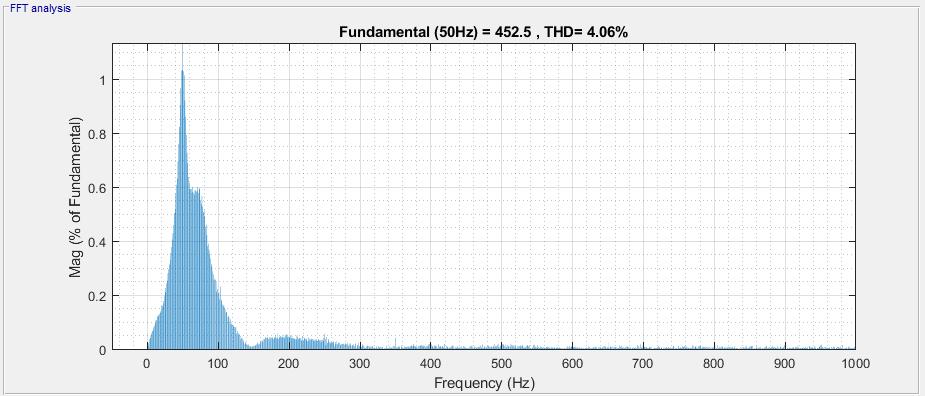
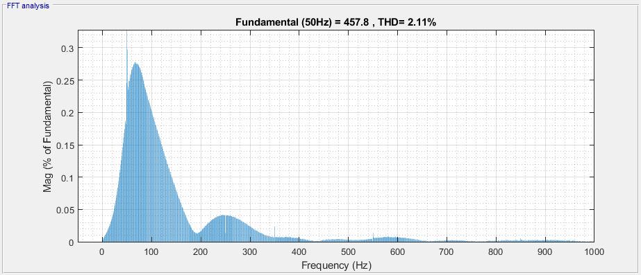
Harmonics can be even (2,4,6,8,10,12 etc) or odd (3,5,7,9,11 etc). Expressed as a percent of the fundamental, the Total Harmonics Distortion is defined as the ratio of the root mean square of the harmonic content, including the harmonic componentsuptothe50th order.TomeettheIEEE519standards,theTHDlimitforvoltageupto1kVis8%.Thedesignof DSTATCOM using PI controller yields around 4.06% THD as shown in figure 13 and that of FL controller yields around 2.11%THDasdepictedinfigure14.
International Research Journal of Engineering and Technology (IRJET) e ISSN:2395 0056
Fig13%THDofLoadcurrentwithDSTATCOMwithPIcontroller
Fig14%THDofLoadcurrentwithDSTATCOMwithFLCcontroller
The comparison of different parameters with and without DSTATCOM (both PI & FL converters) is summarized in the tablebelow.
Table2.ComparisonofparameterswithandwithoutDSTATCOM.
Phaseanglebetweenvoltageand current 48.6degree Zerodegree Zerodegree Powerfactorcorrection 0.66 0.99≈1 0.99≈1 %THD 10.50 4.06 2.11
6. CONCLUSION
In this paper, a distribution network is subjected to non linear and unbalanced loads and the disturbances are included. The DSTATCOM is introduced into the system with PI and FL controllers separately and the performance of the system
International Research Journal of Engineering and Technology (IRJET) e ISSN:2395 0056
Volume: 09 Issue: 05 | May 2022 www.irjet.net p ISSN:2395 0072
underthesecontrollersarepresented ThePIcontrollerbasedDSTATCOMgivesbetterpowerfactorcorrectionand%THD is reduced from 10.50 to 4.06 and also the load voltage is regulated. The FL controller improves the performance by reducingthepoweroscillationsandimprovesthepowerinjectionbyreducingthe overshootin DC link voltage.Itbrings downthe%THDto2.11fromtheinitialvalueof10.50. The%THDisfoundtobemuchimprovedwithFLcomparedtoPI controller.
7. ANNEXURES
Thesimulationparametersareprovidedinthefollowingtable
Table3.SimulationParameters
Parameters Values SupplyVoltage 415V Frequency 50Hz LoadParameters R=30Ω,L=70mH Non Linearloadparameters R=60Ω,L=0.15mH
CouplingTransformerParameters
V1/V2=450V/450V Frequency=50Hz Power=5kVA Filterparameters R=0.01Ω L=16µH C=0.32mF
8. REFERENCES
[1] A.E. Hammad, Comparing the Voltage source capability of Present and future Var Compensation Techniques in TransmissionSystem,IEEETrans,onPowerDelivery.Volume1.No.1Jan1995.
[2] G.Yalienkaya, M.H.J Bollen, P.A. Crossley, “Characterization of Voltage Sags in Industrial Distribution System”, IEEE transactionsonindustryapplications,volume34,No.4,July/August,PP.682 688,1999.
[3]Haque,M.H.,“CompensationofDistributionSystemsVoltagesagsbyDVRandD STATCOM”,PowerTechProceedings, 2001IEEEPorto,Volume1,PP.10 13,September2001.
[4] Anaya Lara O, Acha E., “Modeling and Analysis Of Custom Power Systems by PSCAD/EMTDC”, IEEE Transactions on PowerDelivery,Volume17,Issue:2002,Pages:266 272.
[5]Bollen,M.H.J.,”VoltagesagsinThreePhaseSystems”,PowerEngineeringReview,IEEE,Volume21,Issue:9,September 2001,PP:11 15.
[6]M.Madrigal,E.Acha.,“ModellingOfCustomPowerEquipmentUsingHarmonicsDomainTechniques”,IEEE2000.
[7]R.Meinski,R.PawelekandI.Wasiak,“ShuntCompensationforPowerQualityImprovementUsingaSTATCOMcontroller ModellingandSimulation”,IEEEProce,Volume151,No.2,March2004.
[8] J.Nastran , R. Cajhen, M. Seliger, and P.Jereb,”Active Power Filters for Nonlinear AC loads, IEEE Trans.on Power ElectronicsVolume9,No.1,PP:92 96,Jan2004.
[9] L.A.Moran, J.W. Dixon, and R.Wallace, A Three Phase Active Power Filter with fixed Switching Frequency for Reactive PowerandCurrentHarmonicsCompensation,IEEETrans.OnIndustrialElectronics.Volume42,PP:402 8,August1995.
[10] L.T. Moran, P.D Ziogas, and G.Joos, Analysis and Design of Three Phase Current source solid State Var Compensator, IEEETrans,onIndustryApplications.Volume25,No.2,1989,PP:356 65
© 2022, IRJET | Impact Factor value: 7.529 | ISO 9001:2008 Certified Journal | Page2375