International Research Journal of Engineering and Technology (IRJET) e ISSN: 2395 0056

Volume: 09 Issue: 05 | May 2022 www.irjet.net p ISSN: 2395 0072
International Research Journal of Engineering and Technology (IRJET) e ISSN: 2395 0056
Volume: 09 Issue: 05 | May 2022 www.irjet.net p ISSN: 2395 0072
Abstract Press tools are used to produce a particular component in large quantities, out of sheet metals where the particular component achieved depends upon press tool construction and its configuration. Blanking, bending, piercing, forming, drawing, cutting off, partingoff,embossing, coining, notching, shaving, lancing, dinking, perforating, trimming, curling and other operations are performed using various types of press tool structures.. TheCurrentProgressive die that is being used in the concerned industry performs 3 operations namely: Punching, Sorting, and blanking for the production of the Intercooler Mounting Bracket. These operations are being performed simultaneously i.e., firstly Punching on the sheet metal strip, then sorting it into the correct position for the next operation i.e., Blanking which is the final operation that is performed on this die.Asitperforms these operations simultaneously,thetimetakentogetthefinal product is comparatively more. This also affects the overall production rate, time cycle, and the profit made from this product
Acompounddieperformsonlycuttingoperations(usually blankingandpiercing)whicharecompletedduringasingle pressstroke.
1.Blanking:Blankingisasheetmetalcuttingorshearing process in which the part that is cut from the strip is the required product. In blanking, the die size is equal to the diameter of the blank and the punch is made smaller by subtractingtheclearancesfromthediesize
2.Piercing:Theprincipleofthepiercingprocessissimilar tothatoftheblankingprocess,theonlydifferenceisthathere therequiredpartisthestriponwhichthepiercingisdone. Thedifferencebetweenthe blankingandpiercing.Thedie and punch size differs for the piercing and blanking operation.Forpiercing,thepunchsizeismadeequaltothe sizeoftheholetobepiercedwhilethedieismadelargerby addingtheclearance.
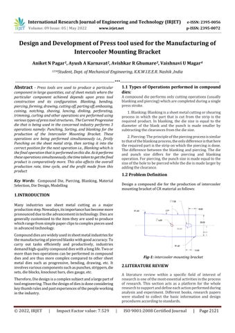
Design a compound die for the production of intercooler mountingbracketofCRmaterialasfollows:
Many industries use sheet metal cutting as a major productionstep.Nowadays,itsimportancehasbecomemore pronouncedduetotheadvancementintechnology.Diesare generallycustomizedtotheitemtheyareusedtoproduce whichrangefromsimplepaperclipstocomplexpiecesused inadvancedtechnology.
Compounddiesarewidelyusedinsheetmetalindustriesfor themanufacturingofpiercedblankswithgoodaccuracy.To carry out tasks efficiently and productively, industries demandhigh qualitycompounddieswithalonglife.Twoor morethantwooperationscanbeperformedincompound dies and are thus more complex compared to other sheet metal dies such as progressive, bending, drawing, etc. It involvesvariouscomponentssuchaspunches,strippers,die sets,dieblocks,knockoutbars,diesgauge,etc.
Therefore,Diedesignisacomplexsubjectandalargepartof toolengineering.Thusthedesignofdiesisdoneconsidering keythumbrulesandpastexperiencesofthepeopleworking intheindustry.
Fig 1: intercooler mounting bracket
A literature review within a specific field of interest of researchisoneofthemostessentialactivitiesintheprocess of research. This section acts as a platform for the whole researchtosupportanddefineeachactionperformedduring analysis and experiment. Different books, research papers were studied to collect the basic information and design proceduresaccordingtostandards
International Research Journal of Engineering and Technology (IRJET) e ISSN: 2395 0056
Volume: 09 Issue: 05 | May 2022 www.irjet.net p ISSN: 2395 0072
S.B.Gaikwadetal[1]discussedintheirpaper“Designand Development of compound die” (2019) that the project mainly focuses on compound die design for existing operationstoreplacethecurrentprogressivediewherein the die contributed to increasing in the production rate, reductionofproductioncostandthetimecyclefrom30to 40secusingsuitabledesignbeingdoneinSolidworksand AnalysisofthepresstoolbeingdoneinAnsys
PawanKumarRaietal[2]in“Causes&PreventionofDefects (Burr)InSheetMetalComponent”(2013)hasdiscussedthe imperfectionsthatarecommoninthesheetmetalindustry whichafteraspecifiedlimitittakestheformofdefect.Also differentChancesoffailureinManufacturing&Assemblyof Tool,needofmaterialhardness,clearancesandalignmentof componentsarediscussed.
Gaurav C. Rathod et al [3] in “Study and Analysis of Press ToolDesign”developapresstoolforPiercingandnotching madeforsheetmetalcomponent.Itshowsastudyofforce reductionmethodusedwhiledesigningthedieandtoensure excellentgeometricalcompatibilityofthemechanicalpress andthedesignedcombinedpresstool.Theyalsodiscussa detailedstudyofvariousmaterialstobeusedfordifferent componentsofthedie,dependingupontheirimportance,the efficiencyofthedieandthevariousfactorsaffectingthem.
MSubramanianetal[4]in“DesignandAnalysisofPressTool toProduceRadiatorStayBracket”(2016)mostlyfocuson thedesigningofpresstooltobeusedin theproductionof thestaybracket,alsomodellingofallthecomponents,and analyzingthestressanddeflectiononthecomponents.
In“Thedesignandfabricationofacompounddietomake hexagonal washer” the authors N. JYOTHIRMAYI et al [5] presentedthedesignandfabricationofacompounddiethat combines blanking and piercing operations. Detailed calculations for Press capacity, plate thickness, Punching, and blanking forces as well as spring calculations were shown.Thesuccessfullydesigneddieisbeingcurrentlyused intheMetalformingLabofChaitanyaBharathiInstituteof Technology,Hyderabad.
The detailed literature review revealed that even though presstoolshavealargeimpactonthetoolindustryveryfew academic researchers are engaged concerning this topic. Withthecontinuousdevelopmentoftheindustry,higherand higher requirements are placed on the press tools. Therefore, the demand for the development of precision, large scale, complex, long life tools exceeds the total development speed thus the most common problem that could be found in this area is the overall accuracy and efficiencythetoolmustprovide.
Themostcommoncauseforthisproblemwasfoundtobe thenon uniformapplicationofforceonthediewhichfurther produces a slight amount of bend formation or burr formationonthefinalproductaswellasthedevelopmentof anunwantedgapbetweenthepunchanddieplateswhich furtherreducesthelifeofthedie.Oneofthewaystoprevent thisistominimizethestressthatwillbeproducedinthedie platecomponentofthepresstool.
Theproject'sgoalsincludeincreasingproductivity,reducing human effort, reducing cycle time, lowering labor costs, designing blanking and piercing die, and developing blanking and piercing die. Product manufacturing competenceamongthemassesisimproved.
4.1
Operations:
Punchinghole=ϕ6mm Punchingcapsule=ϕ15mm BlankingArea=6586.23mm2
Punch and Die Size: Cclearanceperside C = C*t*√(τ max/10) Where,C=Constant C=0.005(veryaccuratecomponent); C=0.01(normalcomponent) t=SheetThickness=1.6mm C=0.01*1.6*√(360/10) …(τmax(HCHCR)=360N/mm2) = 0.12 mm per side
STRIPLAYOUTANDECONOMYFACTOR: ScrapBridge S =1.2*thickness =1.2*1.6=1.92mm Pitch P =57.291mm Width W=132.686mm Area A =6586.23mm2 NumberofRowsN=1
ECONOMYFACTOR=A*N*100/P*W =6586.23*1*100/57.291*132.686 η= 86.641 %
Theproposedstockstriplayouthasamaterialutilizationof 86.641%.Asitisgreaterthan70%,itisaccepted.
DIECLEARANCECALCULATION: Clearanceperside=0.12mmperside
International Research Journal of Engineering and Technology (IRJET) e ISSN: 2395 0056
Volume: 09 Issue: 05 | May 2022 www.irjet.net p ISSN: 2395 0072
PUNCHANDDIECALCULATION:
Blankingoperation=ComponentSize 2(Clearance)
WIDTH=53 2(0.12)=52.76mm
LENGTH=127.96 2(0.12)= 127.72 mm
Piercingoperation=ComponentSize+2(Clearance)
PUNCHINGHOLE=dia.6+(0.12*2)= 6.24 mm PIERCINGCAVITY=dia.7+(0.12*2)=7.24 mm
CUTTINGFORCE(Fsh ): CuttingForce=L*S*τmax Where, L= Peripherallengthofprofiletobecutinmm S= Sheetthicknessinmm. τmax=UltimateshearstressinN/mm²
Hence, ThicknessofDiePlate[Tdieplate ] =3√Fsh =29.624mm = 30 mm
ThicknessofTopPlate =1.5*Tdieplate = 45 mm
ThicknessofKnockoutPlate =0.5*Tdieplate = 15 mm
ThicknessofTopPunchHolderPlate =0.75*Tdieplate = 22.5 mm
ThicknessofStripperPlate =0.75*Tdieplate = 22.5 mm
Totalcuttingperiphery=415.84+38+18.7 =473mm τmax(coldrolledsheet)=2764N/mm2 ...(τmax(CRCA)=276 N/mm2) So,CUTTINGFORCE,Fsh =473*1.6*276 =208673.664N=21271.53kg = 21.2753 Tonnes
PRESSTONNAGE: PRESSTONNAGE=1.2*Fsh =1.2*208673.664 =25.525tonnes = 26 Tonnes
STRIPPINGFORCE(Fst ):
FORCEAPPLIEDONSTRIPPLATE Fst=10%OFCUTTINGFORCE
So,strippingforceinthiscase, Fst=10%OF208673.664 = 20867.367 N
STRENGTHOFBOLT =StrippingForce/No.OfBolts =20867.367/6 = 3477.8945 N/ BOLT
TOTALFORCEREQUIRED Ft=Fsh+Fst Where, Fsh =Shearforce. Fst =Strippingforce. So, Totalforce,Ft=208673.664+20867.367 =229541.031N =23.398Tonnes = 24 Tonnes
TOTALMACHINETONNAGEREQUIRED: Considering20%safetyfactor, F=1.2*Totalforce Totalmachinetonnage=1.2*24 =28.8Tonnes = 29 Tonnes
ThicknessofBottomPunchHolderPlate =0.75*Tdieplate = 22.5 mm
ThicknessofBottomPlate =2*Tdieplate = 60 mm
ThicknessofTopandBottomBackPlate =0.5*Tdieplate = 15 mm
Materialselectionisthefirststepindesigninganyphysical component.Inthecontextofproductdesign,themaingoalof materialselectionistominimizecostwhilemeetingproduct performancegoals.
Thematerialsselectedfordieandpunchasfollows: OHNS: Oil Hardening Non Shrinkage Die steels are mainlyusedforshortruntoolingforcoldformingdies, blanking dies, and cutting tools operating at ambient temperature.
Composition:
2022, IRJET | Impact Factor value: 7.529 | ISO 9001:2008 Certified Journal |
International Research Journal of Engineering and Technology (IRJET) e ISSN: 2395 0056
Volume: 09 Issue: 05 | May 2022 www.irjet.net p ISSN: 2395 0072
relativelylowwhileitprovidesmaterialpropertiesthat areacceptableformanyapplications.
Chemical Composition:
Table No 3: Chemical Composition of MS Steel Carbon 0.16 0.18% Silicon 0.40%max Manganese 0.70 0.90% Sulphur 0.040%max Phosphorous 0.040%max
Mechanical Properties
Table No 4: Mechanical Properties of MS Steel Maxstress 400 560N/mm2 Yieldstress 300 440N/mm2min 0.2%proofstress 280 420N/mm2 min elongation 10 14%min HCHCR(D2): HCHCR is an air hardening, high carbon, high chromiumtoolsteel.Ithashighwearandabrasion resistant properties. It is heat treatable and will offer hardnessintherange55 62HRC,andismachinablein theannealedcondition.D2steelshowslittledistortionon correct hardening. D2 steel’s high chromium content gives it mild corrosion resisting properties in the hardenedcondition.
Chemical composition
Table No. 5:Chemical Composition of D2 Steel Element Content(%) C 1.5 1.75 Mn 0.2 0.4 Cr 11 W 0.4 0.5 V 0.1
Mechanical Properties
Table No-6: Mechanical Properties of D2 Steel UltimateStrength 1020(N/mm2) HardeningTemperature 790 820 oC MaximumHardness 55 62(RC) Wearresistance High Machinability Poor
Tosatisfythedesiredobjectives,theexperimentallayouthas been set up and trials have been performed to test the developedalgorithm.Thischaptercoversin depthdetailsof the experimental setup, procedure and results observed. Differenttrialshavebeenperformedondifferentobjectsof differentmaterials.
Progressivediestampingisametalformingprocesswidely used to produce parts for various industries, such as automotive, electronics, and appliances. Progressive die stampingconsistsofseveralindividualworkstations,eachof which performs one or more different operations on the part.Thepartiscarriedfromstationtostationbythestock stripandiscutoutofthestripinthefinaloperation.
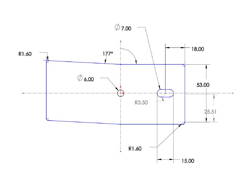
Fig 2: Compounddiesetup
Inthecompounddie,twooperationsareperformedatthe sametimeinonestroke of motion,i.e.,piercingoperation andblankingoperationonthesamestationtoyieldthefinal product.Butastwooperationsarebeingperformedatthe same time, there is no way to extract the final product without causing harm to the worker or obstructing the overalloperation.Thus,aneedtoensuretheproperremoval oftheproductoccurs.Thisisfulfilledbyusingtheknockout operation, where after the blanking and punching operations,thepartgetsattachedtothebufferpadandcan becarriedoutofthetool.Thus,removaloftheproducttakes place.
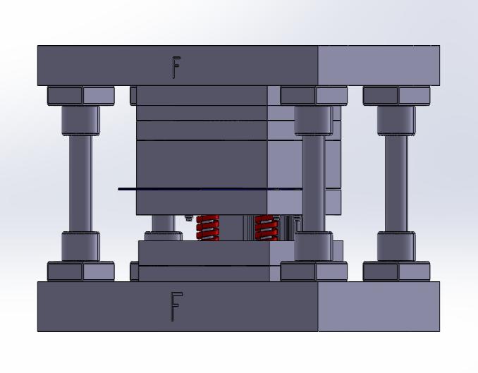
The compound die can be separated into two assembles, namelythetopassemblyandthebottomassembly.Thetop assembly consists of top plate, knockout plate, top punch back plate, die plate, punch plate, buffer pad and most importantly,thetoppunchesi.e.,piercingpunchandcapsule punch. The bottom assembly consists of the stripper, stripperplate,blankingpunch,bottompunchholder,bottom backplates,bottomplateandsprings.Theguidepillarsand guide bush help in the proper orientation of both the assembliesandensureproperworkingofthecompounddie soastogettheexactrequiredproduct.
Fig 2 depicts the die as it appears during the operation, wherethetopassemblyandbottomassemblyisincontact with each other and the operation of piercing by the top punches and blanking by the bottom punchestakes place. The top assembly is in motion, on which the press ram
2022, IRJET | Impact Factor value: 7.529 | ISO 9001:2008 Certified Journal |
International Research Journal of Engineering and Technology (IRJET) e ISSN: 2395 0056
Volume: 09 Issue: 05 | May 2022 www.irjet.net p ISSN: 2395 0072
applies the required force, and the descending motion is initiated.
Whilethetopassemblyisnowascendingupwards,thefinal productgetsattachedtothebufferpad,whereafterreaching acertainpositiontheknockoutpinpushestheknockoutpad, whichcreatesanimpactonthebufferpaduponwhichthe product is attached, and thus due to sudden shock, the productfalldownandisejectedfromthetool.Allofthese operationstakeplaceinjustonestrokeofmotion.
International Journal of Engineering Research and Applications(IJERA)ISSN:2248,9622,pp.511 515.
[3] Rathod,G.C.,Raut,D.N.andAdlinge,S.,2017.Studyand Analysis of Press Tool Design. International Journal of EngineeringResearchandTechnology(IJERT),6(07).
[4] Subrahmanyam, M. and Mokhalingam, A., Design, and AnalysisofPressTooltoProduceRadiatorStayBracket, International Journal of Engineering Research & Technology(IJERT)Vol.5Issue06,June 2016
[5] JYOTHIRMAYI, N. and RAO, D., THE DESIGN AND FABRICATION OF A COMPOUND DIE TO MAKE HEXAGONAL WASHER, International Journal of Mechanical and Production Engineering Research and Development(IJMPERD),Vol.9,Issue4,Aug2019,517 528
[6] Nizam,A.,Kumar,M.andSoni,M.M.,2013.Optimization of Sheet Metal Thickness and Die Clearance of ProgressivePressToolUsingFiniteElementAnalysisand Artificial Neural Network. International Journal of ScienceandResearch(IJSR).

Fig 3: Final Compound Blanking Die
ANIKETNIVRUTTIPAGAR Student, Department of Mechanical Engineering, K.K.W.I.E.E.R.,Nashik,India
Successfullydesignedthepresstooltoperformblanking andpiercingdieoperations.
Analysis and theoretical calculations when compared showasignificantamountofsimilarity,thusvalidating thediedesign.
Bychoosingtheappropriatematerialfordie,punch,and otherparts,thetoollifecouldbeincreasedformaximum range.
Ensures less fatigue and required skill to the operator duetofeweramountsofmovementandthussavingtime. ReductioninProductionandmanpowercost.
Aone timeinvestmentintherequisiteequipmentwould ensurealong termsupplyofsuperiorqualityproducts, generatinghugeprofitsforthemanufacturers.
[1] Gaikwad, S.B., Sonawane, J.B., Kalamkar, K.L. and Kale, A.B.,2019.DesignAndDevelopmentofCompoundDie, ProceedingsofSecondShriChhatrapatiShivajiMaharaj QIP Conference on Engineering Innovations In AssociationwithNovateurPublicationsJournalNX ISSN No:2581 4230
[2] Rai,P.K., Mohammad, A.andJafri, H.Z.,2013.Causes & preventionofdefects(Burr)insheetmetalcomponents.


AYUSHANILKARNAVAT Student, Department of Mechanical Engineering, K.K.W.I.E.E.R.,Nashik,India
AVISHKARRAJENDRAGHUMARE Student, Department of Mechanical Engineering, K.K.W.I.E.E.R.,Nashik,India
VAISHNAVIUMESHMAGAR Student, Department of Mechanical Engineering, K.K.W.I.E.E.R.,Nashik,India