International Research Journal of Engineering and Technology (IRJET) e ISSN:2395 0056

Volume: 09 Issue: 05 | May 2022 www.irjet.net p ISSN:2395 0072
International Research Journal of Engineering and Technology (IRJET) e ISSN:2395 0056
Volume: 09 Issue: 05 | May 2022 www.irjet.net p ISSN:2395 0072
1
1Engineering Consultantant and Trainer, Chandigarh, India ***
Abstract Autonomous Vehicles are sharply gaining popularity in the engineering and technology sector. This study aims to optimise the distance measurement of an Autonomous Vehicle using an ultrasonic sensor and LIDAR sensor for education purposes. An experiment is performedto find an indoor operating range of an ultrasonic and LIDAR sensor. In addition, Full Factorial design is used to experimentally find the effect of angle, distance and object shape on the sensor measurement error rate and the object detectionrate.Theresultshowsthatanultrasonic andLIDAR sensor has indoor operating ranges different from the manufacturer’s specifications. Both sensors are sensitive to angle, distance and object shape. It is concluded that the ultrasonic and LIDAR sensor has indoor operating ranges of 2000 mm and 250 mm. The ultrasonic sensor has minimum measurement error for cylinder shape objects, 0° angle and a distance value of 500 mm. It has a maximum object detection rate for cuboid shape objects, an angle value of 0° and a distance value of 500 mm, respectively. LIDAR sensor has a minimum measurement error for cuboid shape objects, 0° angle and a distance value of 250 mm. It has a maximum object detection rate for cuboid shape objects,0° angle value and distance value of 250 mm, respectively.
Key Words: Autonomous Vehicles, Full Factorial Design, Ultrasonicsensor,LIDARsensor,Distancemeasurement.
Theautonomousvehicles(AV)marketisexpectedtoriseby about59% between 2020and2023 [1].AVuses different sensors to interact with the environment to automate the process.Thesoftware'susedtoincreasetheproductivityof theautomatedtechnology.AVsareusedinprivatevehicles, transportationandthefarmingindustry.LIDARsensorsare usedinAVtodetectobjects200mto300mawayandemit short pulses to measure more than a million points per second. It creates three dimensional maps of the environmenttovisualisetheobjectaroundtheenvironment. Theyassistincoveringa360°viewandhelpcreatea3Dmap tohaveaclearsightofwhatishappeningaroundthevehicle and make it capable of "seeing "[2]. Google AV company Waymo started designing and producing their LIDAR sensorstoreducecostsanddevelopAVforthemassmarket. TeslaAVcanhelpautosteer,autopark,autolanechangeand fullyself drivelongdistancesonhighwaysforasignificant periodwithouthumanassistance.
However, Tesla is not using LIDAR sensors costing 75000 dollars per unit. Instead, it uses ultrasonic sensors for car detectionandcollisionprevention[3].Ultrasonicsensorsare a cheap alternative to LIDAR sensors for object detection systemsandalgorithmsinAV.Itsendsultrasonicimpulses thatarethenreflectedbytheobstacle.Therefore,ithelpsAV toperformaccordingtothebarrier.Ultrasonicsensorscan rangeupto5.5mandhavelimitationssuchasdifficultyin detectingobjectsgoingatafastspeed.Theyarevulnerable to jamming and spoofing attacks leaving the sensor physicallyunabletofunctionandcreatingfalsepositives.It could lead to a potential incident without user supervision[4].Themeasurementoftheultrasonicsensoris sensitive to temperature and the angle of the target. In addition, some materials are more absorbent than others, and these will reflect less ultrasound [5]. Therefore, it complicates measuring the distance with an ultrasonic sensoralone.
On the other hand, the LIDAR sensor cannot recognise transparent objects. So it is advantageous to use an ultrasonic sensor and LIDAR sensor to detect transparent objects [6]. Instead of taking 100 measurements per measuring location in an ultrasonic sensor, 20 measurements per measuring location create a relatively good environment occupancy grid utilised for robot navigation tasks [7]. The operating distance commonly stated by manufacturers of air ultrasound range finding modules and devices can be very misleading. It should be estimatedexperimentally[8].
The literature review indicates that using ultrasonic and LIDAR sensors for distance measurement is more advantageousthanutilisingeithersensoralone.Therefore, thisstudyaimstooptimisethedistancemeasurementofan AVusinganultrasonicsensor(HC SR04)andLIDARsensor (VL53L0X)foreducationpurposes.Themainobjectivesof this research are 1) To experimentally find an effective indooroperatingrangeofanultrasonicsensorandLIDAR sensor; 2) To experimentally find the effect of an angle, distanceandobjectshapesontheerrorrateanddetection rate of an ultrasonic sensor and LIDAR sensor. The study intends to contribute to the literature on optimising the distancemeasurementofanAVusingultrasonicandLIDAR sensors.
International Research Journal of Engineering and Technology (IRJET) e ISSN:2395 0056
Volume: 09 Issue: 05 | May 2022 www.irjet.net p ISSN:2395 0072
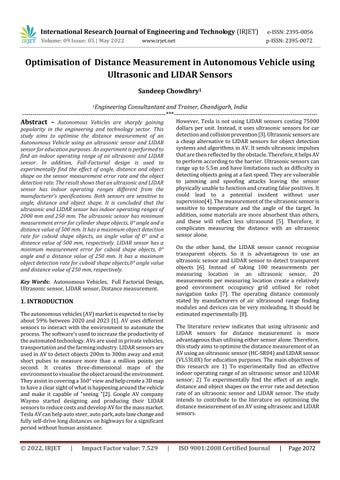
TheAV body(Fig. 1)isbuilt withupperandlowerplastic sheets.Agearedmotorisattachedtoeachofthefourwheels mounted on the side of the plastic sheets. An ultrasonic sensor is mounted on the breadboard. LIDAR sensor is mountedonthefrontsideoftheAVbetweenthelowerand upper plastic sheet. The LIDAR sensor is located on the centre line between the transmitter and receiver of the ultrasonic sensor. The breadboard is powered with an ArduinoUnomicrocontrollerthroughthelaptop.Ultrasonic sensorTrigandEchopinsareconnectedtopins10and9on Arduino.LIDARsensor’sSDAandSCLpinsareconnectedto analoguepinsA4andA5onArduino.
I/O: 20mA; DC current for 3.3V: 50Ma; Flash Memory: 32KB,0.5KB used by loader; Clock speed: 16MHz; Length, width,weight:68.6mm,53.4mm,25grespectively.
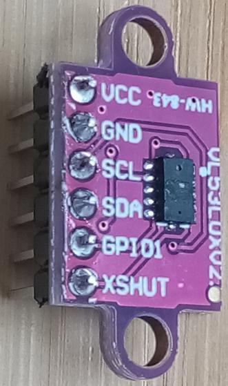
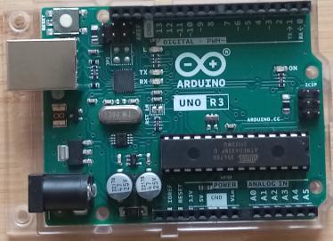
ArduinoUnomicrocontroller(Fig.2)technicalspecifications are Atmega328P; operating voltage:5V; Input voltage (recommended): 7 12V; Input V. (limit): >6, <20V; PWM Digital I/O Pins:6; Analogue Input pins: 6; DC current per
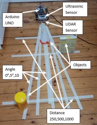
Ultrasonicsensor(Fig.3)technicalspecificationsareCurrent voltage(V):DC5V;Groundvolatge(G):0V;Workingcurrent (C): 15mA; Working frequency (F): 40KHz; Range (Max/Min): 400 cm/2 cm; Angle measure: 5 15 degree; Triggersignal:10uSTTLpulse;Echosignal:Dependonmax range of TTL; Dimensions: 45 mm x 20 mm x 15 mm respectively
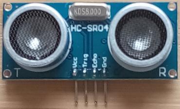
LIDARsensor’s(Fig.4)technicalspecificationsarePackage: Optical LGA12; Size: 4.40 x 2.40 x 1.00 mm; Operating voltage: 2.6 to 3.5V; Operating tempertaure: 20 to 70°C; Infraredemitter:940nm;I2C:Upto400kHz(FASTmode) serialbusAddress:0X52respectively.
Three3 dimensionalobjectsusedareCuboid:156x3x213 mm;Cylinder:Diameter85mmandheight167mm;Cone: base diameter 113 mm and vertical height 242 mm respectively.
International Research Journal of Engineering and Technology (IRJET) e ISSN:2395 0056
Volume: 09 Issue: 05 | May 2022 www.irjet.net p ISSN:2395 0072
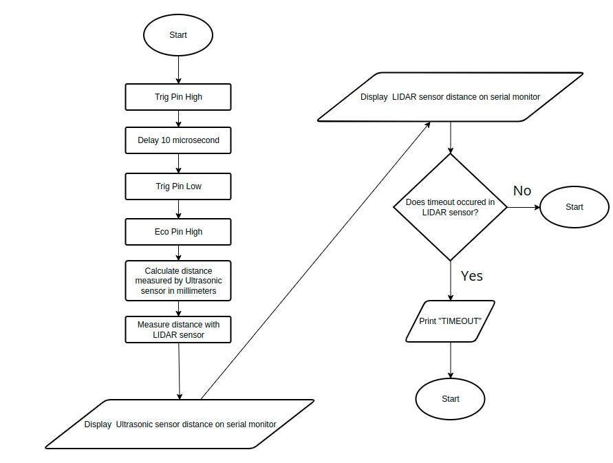
Fig 5:FlowchartofArduinoprogram
Table1showsthethree levelsettingsoftheparameters such as shape, angle and distance. The sensors' measurement error rate and object detection rate are selectedastheresponse.
Parameter
Level 1 Level 2 Level 3
Shape Cuboid Cylinder Cone Angle(deg) 0° 5° 10° Distance(mm) 250 500 1000
Initially, the Minitab 2019 software is used to design the random run order for the full factorial experiment. The parametersarechosenascategoricalinnature.Itconsistsof 27points(Run1 27),onereplicateandoneblock,asshown inTable2.
Run Order Shape Angle (deg) Distance (mm)
1 Cylinder 0° 500 2 Cone 5° 500 3 Cone 10° 1000 4 Cylinder 5° 250 5 Cuboid 5° 250 6 Cylinder 0° 1000 7 Cylinder 10° 500 8 Cone 10° 250 9 Cuboid 10° 500 10 Cuboid 10° 250 11 Cuboid 10° 1000 12 Cone 0° 1000 13 Cuboid 0° 500 14 Cylinder 0° 250 15 Cylinder 10° 1000 16 Cuboid 5° 1000 17 Cone 5° 250 18 Cylinder 5° 1000 19 Cone 5° 1000 20 Cone 10° 500 21 Cylinder 5° 500 22 Cuboid 5° 500 23 Cylinder 10° 250 24 Cuboid 0° 1000 25 Cuboid 0° 250 26 Cone 0° 500 27 Cone 0° 250
First,thecuboidshapeobjectisplacedatanangleof0°ata distanceof250mm,500mm,1000mm,2000mmand3000 mm,respectively.Twentymeasurementsofboththesensors arerecordedateachdistancevalue.
International Research Journal of Engineering and Technology (IRJET) e ISSN:2395 0056
Volume: 09 Issue: 05 | May 2022 www.irjet.net p ISSN:2395 0072
Second, the object is placed as per the shape, angle, and distance'sfirstrunordervalues,asshowninTable2.Ten distancemeasurementsarerecordedforboththeUltrasonic sensor and LIDAR sensor, as shown in Fig. 6. During the experiment,itisnotedthatwhentheLIDARsensorcannot detectanobject,itoffersanenormousvalueof8190mmor 8191mm.Similarly,whenanUltrasonicsensorcannotdetect anobject,itshowsanimmensevalueof11652mmEtc.In suchcases,itisconsideredthatthesensorwithamaximum measurement error rate and no detection. Among the ten recordedvaluesforeachmeasurementlocation,themode valueisusedasthesensor's reading.Themaximumerror readingisrecordedasthemeasurementintheabsenceof mode.Itisusedtocalculatethesensorerrorrate.
Similarly, out of ten recorded measurements, if the enormousvalueisrecordedsixtimes,thesensordetection rate is calculated as 40%. Again, the response values are recordedfor theraminingrunordersasshowninTable2 Afterwards, Minitab software is used to analyse the full factorialdesign.
Fig -6:Serialmonitorsensormeasurementdispaly
Fig 7:Sensorsdistancemeasurementat250mm
ThegraphinFig.7showsthatfortwentymeasurementsof the exact measurement location, an ultrasonic sensor can measurethedistanceof250mmwithameasurementerror of about 10%. On the other hand, the LIDAR sensor has a measurementerrorofabout80%.
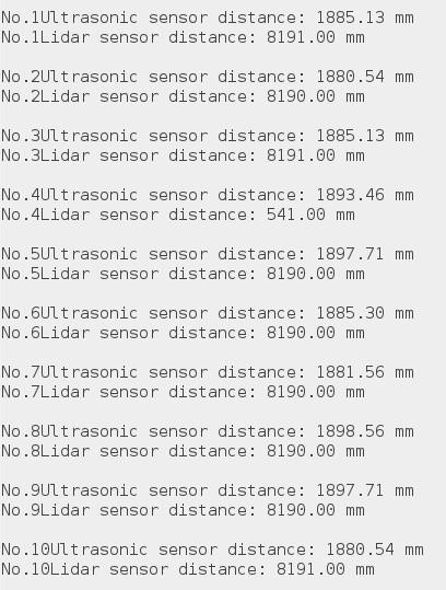
Fig 8:Sensorsdistancemeasurementat500mm
ThegraphinFig.8showsthatfortwentymeasurementsof the exact measurement location, an ultrasonic sensor can measurethedistanceof500mmwithameasurementerror below 10%. On the other hand, the LIDAR sensor has a measurementerrorofabout100%.
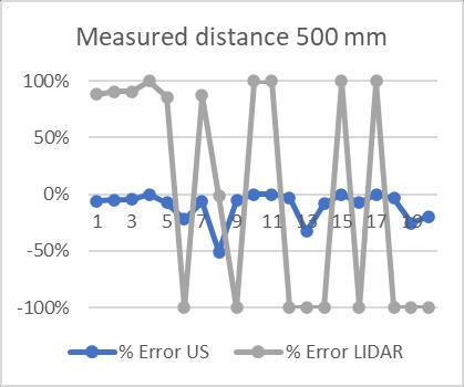
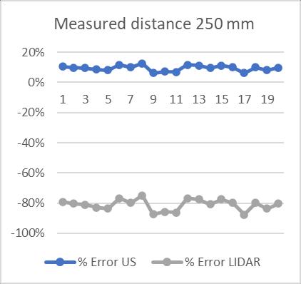
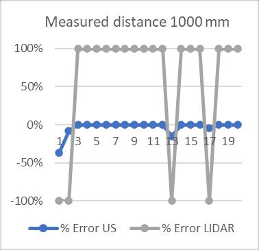
Fig -9:Sensorsdistancemeasurementat1000mm
International Research Journal of Engineering and Technology (IRJET) e ISSN:2395 0056
Volume: 09 Issue: 05 | May 2022 www.irjet.net p ISSN:2395 0072
ThegraphinFig.9showsthatfortwentymeasurementsof the exact measurement location, an ultrasonic sensor can measurethedistanceof1000mmwithameasurementerror below 5%. On the other hand, the LIDAR sensor has a measurementerrorofabout100%.
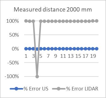
The graph in Fig. 10 shows that an ultrasonic sensor can measurethedistanceof2000mmwitha0%measurement errorfortwentymeasurementsoftheexactlocation.Onthe other hand,theLIDAR sensor hasa measurement error of about100%.
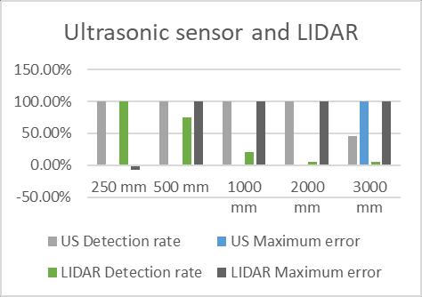
ThegraphinFig.12showsthattheultrasonicsensorhasan almost negligible measurement error for a distance up to 2000mmandhasa100%measurementerroratadistanceof 3000mm.Second,theLIDARsensorhasanalmostnegligible measurementerroruptothedistanceof250mmandhasa 100% measurement error for the other distance values. Third,theultrasonicsensorhasa100%objectdetectionrate for distances up to 2000 mm and around a 40% object detectionratefordistancevaluesof3000mm.Fourth,the LIDARsensorhasobjectdetectionratesof100%atadistance of 250 mm, approximately 75% at a distance of 500 mm, about 25% at a distance of 1000 mm and below 5% for remainingdistancevalues.
ThegraphinFig.11showsthatfortwentymeasurementsof the exact measurement location, an ultrasonic sensor can accurately measure the distance of 3000 mm for the first sevenreadings.Ithasameasurementerrorofabout60%for theremainingreadings.Ontheotherhand,theLIDARsensor hasameasurementerrorabove95%.
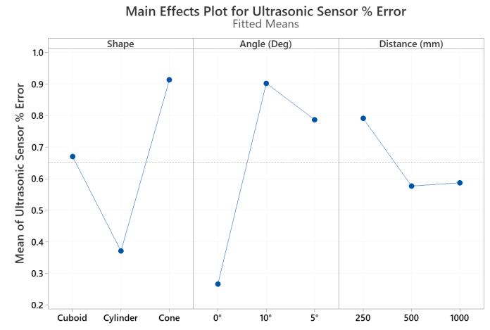
The graph in Fig. 13 shows that an ultrasonic sensor has minimummeasurementerrorforcylindershapeobjects,0° angle and a distance value of 500 mm. It has maximum measurementerrorforconeshapeobjects,10°anglevalue anddistancevalueof250mm,respectively.
International Research Journal of Engineering and Technology (IRJET) e ISSN:2395 0056
Volume: 09 Issue: 05 | May 2022 www.irjet.net p ISSN:2395 0072
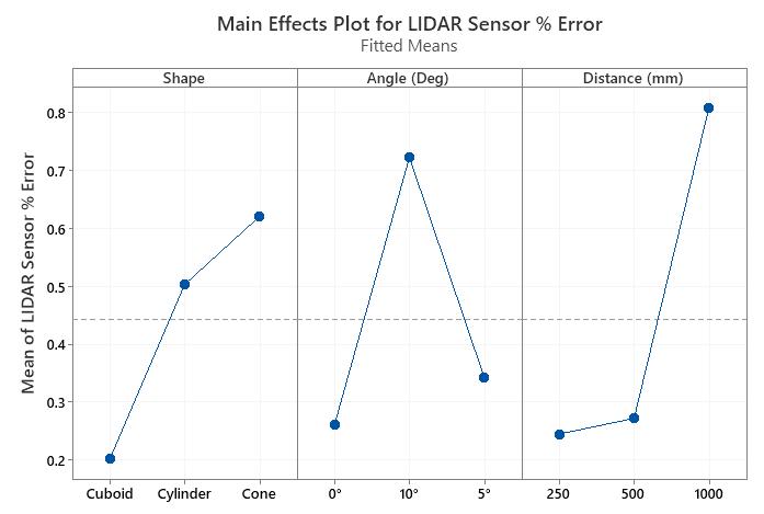
The graph in Fig. 14 shows that the LIDAR sensor has a minimum measurement error for cuboid shape objects, 0° angle and a distance value of 250 mm. It has maximum measurementerrorforconeshapeobjects,10°anglevalue anddistancevalueof1000mm,respectively.
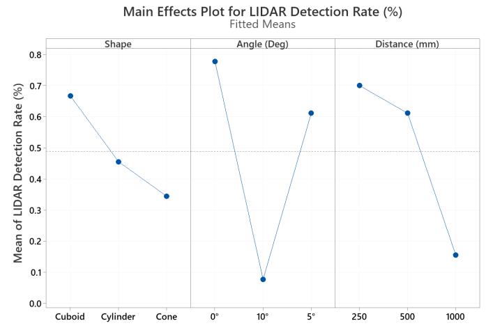
The graph in Fig. 16 shows that the LIDAR sensor has a minimumobjectdetectionrateforcone shapedobjects,10° angleanda distancevalueof1000mm.Ithasa maximum objectdetectionrateforcuboidshapeobjects,0°anglevalue anddistancevalueof250mm,respectively.
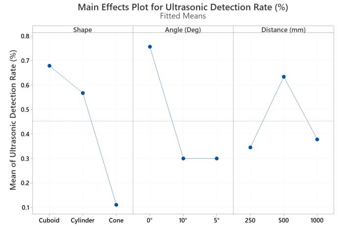
ThegraphinFig.15showsthatanultrasonicsensorhasa minimumobjectdetectionrateforconeshapeobjects,10° angle and a distance value of 250 mm. It has a maximum objectdetectionrateforcuboidshapeobjects,0°anglevalue anddistancevalueof500mm,respectively.
ThegraphinFig.17showsthatinanultrasonicsensor,to maximise the object detection rate and minimise the measurementerrorrate,theoptimalsettingsareanobjectof cuboidshape,anglevalueof0°anddistancevalueof500mm, respectively.
International Research Journal of Engineering and Technology (IRJET) e ISSN:2395 0056
Volume: 09 Issue: 05 | May 2022 www.irjet.net p ISSN:2395 0072
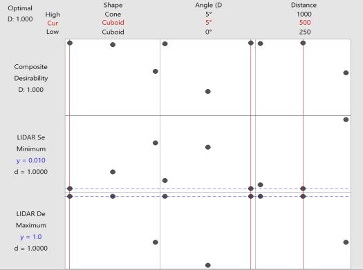
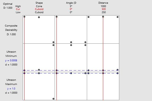
The graph in Fig. 18 shows that in the LIDAR sensor, to maximise the object detection rate and minimise the measurementerrorrate,theoptimalsettingsareanobjectof cuboidshape,anglevalueof5°anddistancevalueof500mm, respectively.
First,foranultrasonicsensor,aneffectiveindooroperating range with minimum measurement error and maximum detectionrateis2000mm(Fig.12).However,aftertheinitial sevenaccuratemeasurementreadingsatadistancevalueof 3000mm,theultrasonicsensorstartsgivingameasurement error of above 60% (Fig. 11). It might be possible for an ultrasonic sensor to provide an accurate distance measurementreadingforamoresignificantsizeobjectata distanceof3000mm.Alternatively,theuseoftwoultrasonic sensors in front of the AV might reduce the measurement error and maximise the detection rate of the sensor at a distancevalueof3000mmormore.Thisstudyagreeswith [8]toexperimentallyestimatetheoperatingdistanceofair ultrasoundrangefindingmodulesanddevices. Second,fora LIDAR sensor, the indoor operating range with minimum measurement error and maximum object detection rate is 250mm(Fig.12).However,theLIDARsensorhasarounda 75% detection rate at a distance value of 500 mm and approximatelya25%objectdetectionrateatadistancevalue of 1000 mm. It might be possible to use a LIDAR sensor effectivelyabove250mmtoincreaseanobjectdetectionrate by making it rotate within an angle range continuously in frontofanAVwiththehelpofamotorratherthankeepingit stationary. It might be possible for the LIDAR sensor to measure more significant size objects with minor measurementerroratdistancevaluesabove250mm.Third, an ultrasonic sensor measurement error rate and object detectionratearesensitivetotheobject'sshape,angleand distance, as shown in Fig. 13 and Fig. 15. In addition, the graph in Fig. 17 indicates that the optimal settings for an ultrasonicsensorareobjectsofcuboidshape,anglevalueof 0°anddistancevalueof500mm,respectively.Thefindingof the optimal settings of an ultrasonic sensor for the cuboid bodyisinagreementwith[9].Itindicatesthatmorethanone ultrasonicsensormaybeusedonanAVtoincreasedistance measurement reliability with an ultrasonic sensor for different shapes, angles, and distances. Fourth, the LIDAR sensor'smeasurementerrorrateandobjectdetectionrate are sensitive to the object's shape, angle and distance, as showninFig.14andFig.16.
In addition, the graph in Fig. 18 shows that the optimal settingsfortheLIDARsensorareanobjectofcuboidshape, anglevalueof5°anddistancevalueof500mm,respectively. It shows that the LIDAR sensor and an ultrasonic sensor increase the object detection zone in front of the AV. It indicatesthatbothsensorsshouldbeusedinconjunctionto improve the reliability and accuracy of the distance measurementandanobjectdetectionwiththemratherthan
usingthemalone.Thisfindingagreeswith[10]thatamore reliablecaroperationisachievedbyusingdatafromsensors aftersensorfusion.
Thisstudyaimstooptimisethedistancemeasurementofan AVusinganultrasonicsensor(HC SR04)andLIDARsensor (VL53L0X). The main objectives of this research are 1) To experimentallyfindaneffectiveindooroperatingrangeofan ultrasonic sensor and LIDAR sensor; 2) To experimentally findtheeffectofanangle,distanceandobjectshapesonthe error rate and detection rate of an ultrasonic sensor and LIDARsensor.First,thefindingsareforanultrasonicsensor, an effective indoor operating range with minimum measurementerror,andamaximumdetectionrateis2000 mm.Second,foraLIDARsensor,theindooroperatingrange with minimum measurement error and maximum object detection rate is 250 mm. Third, an ultrasonic sensor has minimummeasurementerrorforcylindershapeobjects,0° angle and a distance value of 500 mm. It has maximum measurementerrorforconeshapeobjects,10°anglevalue and distance value of 250 mm, respectively. Fourth, an ultrasonic sensor has a minimum object detection rate for cone shapedobjects,10°angleandadistancevalueof250 mm.Ithasamaximumobjectdetectionrateforcuboidshape objects, 0° angle value and distance value of 500 mm, respectively. Fifth, the LIDAR sensor has a minimum measurementerrorforcuboidshapeobjects,0°angleanda distance value of 250 mm. It has maximum measurement error for cone shape objects,10° angle value and distance valueof1000mm,respectively.Sixth,theLIDARsensorhasa minimumobjectdetectionrateforcone shapedobjects,10° angleanda distancevalueof1000mm.Ithasa maximum objectdetectionrateforcuboidshapeobjects,0°anglevalue anddistancevalueof250mm,respectively.Thelimitationof thisresearchisthatallmeasurementsarerecordedwhilethe AV is stationery. The suggestion for further research is to performthedistancemeasurementwithmovingAVanduse thedata fromthesensorsaftersensorfusiontodetectthe objectsandmeasuredistance
[1] https://www.globenewswire.com/news release/2020/05/20/2036203/0/en/Global Autonomous Cars Market 2020 to 2030 COVID 19 Growth and Change.html M. Young, The Technical Writer’sHandbook.MillValley,CA:UniversityScience, 1989.
[2] J. Hecht, 2018, “Lidar for Self driving Cars,” Opt. Photonics News, 29(1), pp. 26 33.K. Elissa, “Title of paperifknown,”unpublished.
[3] T Khan Mohd, R Ayala, Sensors in Autonomous Vehicles:ASurvey,JournalofAutonomousVehiclesand Systems,July2021,Vol.1,pp1 12
[4] C. Yan, W. Xu, and J. Liu, 2016, “Can You Trust Autonomous Vehicles: Contactless Attacks Against SensorsofSelf drivingVehicle,”DefCon,24(8),p.109.
[5] Michal Kelemen , Ivan Virgala , Tatiana Kelemenová , ĽubicaMiková ,PeterFrankovský,TomášLipták,Milan Lörinc , Distance Measurement via Using of Ultrasonic Sensor,JournalofAutomationandControl,2015,Vol.3, No.3,71 74.
[6] T. Zhang∗ , Z. J. Chong∗ , B. Qin∗ , J. G. M. Fu† , S. Pendleton∗,M.H.AngJr.,SensorFusionforLocalization, MappingandNavigationinanIndoorEnvironment,7th IEEE International Conference Humanoid, Nanotechnology, Information Technology Communication and Control, Environment and Management(HNICEM)TheInstituteofElectricaland ElectronicsEngineersInc.(IEEE)PhilippineSection12 16 November 2014 Hotel Centro, Puerto Princesa, Palawan,Philippines.
[7] J Hanzel,M KĐúþik ,L Jurišica,A Vitko,Rangefinder modelsformobilerobots,ProcediaEngineering48(2012 )pp189 198.
[8] O. S. Sonbul , A. N. Kalashnikov, Determining The Operating Distance of Air Ultrasound Range Finders: CalculationsandExperiments,InternationalJournalof Computing,13(2)2014,125 131.
[9] Anuruk,TheStudyandComparisontheResultsofObject Height Measurement with Different Shape using Ultrasonic Sensor, Engineering Transactions, Vol. 23, No.1(46)Jan Jun2020.
[10] MuhammadIrfanHaiderJilani,Topic02:SensorFusion TechniquesforAutonomousDrivingApplications

Er. Sandeep Chowdhry has done Bachelor of Engineering in Mechanical Engineering with a Specialisation in Manufacturing EngineeringfromS.L.I.E.T.Punjab, India and is interested in solving industrialproblemsandimparting trainingtotheprofessionalsinthe industry.(studentsuniversityonline @gmail.com)
International Research Journal of Engineering and Technology (IRJET) e ISSN:2395 0056 Volume: 09 Issue: 05 | May 2022 www.irjet.net p ISSN:2395 0072 © 2022, IRJET | Impact Factor value: 7.529 | ISO 9001:2008 Certified Journal