International Research Journal of Engineering and Technology (IRJET)

Volume: 09 Issue: 05 | May 2022 www.irjet.net
e ISSN:2395 0056
p ISSN:2395 0072
International Research Journal of Engineering and Technology (IRJET)
Volume: 09 Issue: 05 | May 2022 www.irjet.net
e ISSN:2395 0056
p ISSN:2395 0072
Abstract:
The Power Quality Improvement In Electrical Railway Power System provides continuous power factor correction without manual capacitive bank loading. A PFC controller provides power factor correction and peak current limiting for a switch mode power converter of anytopology(buck, boostor buck boost), While not having to at once experience inductor current.ThePFCmanipulatemethod entailstheuseof a piecewise polynomial analog pc (AC) to compute energytransistoron instancesaccordingwithseparate polynomialtransfer functionsforpower factorcontrol and peak current linking using as inputs current representationsoflineinputvoltage(VLN),loadoutput voltage(VLD), andlong termcurrentdemand(VCD).A conduction cycle is initiated by way of sensing while the price of exchange inside the inductor modern reacheszerousinganauxiliarywindingonthecutting edge garage inductor, and terminated after the computed on time to implement either power componentcontrolor top-modern-day-restricting.The Reactive Power charge on your electricity bill is directly targeted againstthose companies who do not demonstrateclearenergyefficiencyuse. Wewilllocate this rate itemized on electricity bill. Reactive strength expenses canbe madesubstantiallysmaller bymeans of the introduction of Power Factor Correction Capacitors which is a broadly identified method of reducing an electrical load and minimizing wasted energy, improving the efficiency of a plant and reducing the electricitybill. It is not always necessary to reach a power factor of 1. A cost effective solution can be achieved by increasing your power factor to greater than0.95. This project makes use of regulated 5V,750mApowerdeliver.7805threeterminal voltage regulator is used for voltage regulation and a Bridge type full waverectifier isused torectifytheacoutput ofsecondaryof230/12Vstepdowntransformer.
This mission offers non stop energy factor correction with out manual capacitive bank loading. A PFC controllerprovidespowerthingcorrectionand height cutting edge restricting for a transfer mode power converter of any topology (dollar, increase or greenback boost), while not having to without delay experience inductor current.The PFC control method involves the use of a piecewise polynomial analog computer (AC) to compute energy transistor on times according with separate polynomial transfer capabilities for power thing manage and peak present day linking using as inputs cutting edge representationsoflineentervoltage(VLN),loadoutput voltage (VLD), and long term present day call for (VCD).A conduction cycle is initiated through sensing when the rate of change within the inductor modern dayreaches0theusageofanauxiliarywindingonthe current garage inductor, and terminated after the computedon timetoenforcebothpower thing control orpeak-cutting-edge-proscribing.
Powerfactor(pf)isdescribedastheratiooftheactual energy (P) to obvious strength (S), or the cosine (for pure sine wave for each present day and voltage) that representsthesectionperspectivebetweenthecurrent andvoltagewaveforms.Theelectricityaspectcanvary amongzeroand1,andcanbebothinductive (lagging) orcapacitive(main)
Some of the benefits of improving your power factor include:
Increased system capacity and reduced system losses inyourelectricalsystem
Asst. Prof. S.Md.Mazhar Ul Haq, Rayees Ahmed, Syed Aakif Faraz, Abdul AbrarDepartment of Electrical and Electronics Engineering, ISL Engineering College, Bandlaguda, Hyderabad, India.
International Research Journal of Engineering and Technology (IRJET)
Volume: 09 Issue: 05 | May 2022 www.irjet.net
Everyembeddeddevicerequiresdcvoltageandthatto beabletobe5vdeliverWehavebecome230v,50Hzin ourfamilyapplications.Wecanbeusedto functionthe house appliances like T.V, cooler, fan, light’s Digital electronic gadgetsneed virtualsupplyandweareable togetdeliverfromregulatedstrengthsupplyblock.
Transformerisaelectromagneticdevicewhichinduces the voltage because of magnetic subject gift among primary and secondary windings. It has two windings referred to as as primary winding and secondary winding. We are giving input 230v enter voltage at number one side. The output of transformer is 9v(ac best).In this project we're the usage of 9vstep down transformer
Rectifier is circuit which converts the ac in to dc. We havetwostylesofrectifier.Inthisventureweareusing bridge rectifier because the efficiency of the bridge rectifierishighexaminetoallrectifiers
e ISSN:2395 0056
p ISSN:2395 0072
Theoutputofrectifierisn'talwayspureDC.Itcanalso compriseafewripplecomponentsthatispulsatingDC. To remove this ripple additives that are found in outputwe'reusingfilter.Filterisacircuitwhichisused toeliminatetheripplespresentinrectifiedoutput.
The output of filter is not constant output voltage it will. Varies in step with adjustments in input however we want steady output voltage. For this reason we're theuseofvoltageregulator.Regulatorisdescribedasit is a tool which willholdconsistentoutputirrespective of adjustments in enter. The most famous regulator collection is 78xx series. This collection have extra advantages.Wearetheuseof7805voltageregulatorto hold consistent 5v output voltage regardless of changesininputvoltage
Amicrocontrollerisasmallpconasingleincorporated circuit consisting of a extraordinarily easy CPU blended with assist capabilities along with a crystal oscillator,timers,watchdogtimer,serialandanalogI/O etc. Microcontrollers are also used in scientific, excessive technology, and aerospace projects. Microcontrollers are designed for small or devoted programs Some microcontrollers may additionally functionatclockfeefrequenciesas lowasfourkHz,as this is good enough for plenty normal packages, allowing low energy consumption (mill watts or microwatts)Microcontrollers are utilized in robotically managed merchandise and devices, which include vehicle engine control structures, far flung controls, workplace machines, home equipment, strength gear, and toys. A microcontroller may be taken into consideration a self contained system with a processor, reminiscence and peripherals and may be used with an embedded machine Microcontrollers oughttoproviderealtimeresponsetooccasionsinthe embedded machine they're controlling. When certain events arise, an interrupt device can signal the processor to suspend processing the current practise series and to begin an interrupt carrier habitual (ISR, or "interrupt handler").Embedded processors are
International Research Journal of Engineering and Technology (IRJET)
Volume: 09 Issue: 05 | May 2022 www.irjet.net
typically used to govern devices, they once in a while need to accept input from the device they are controlling
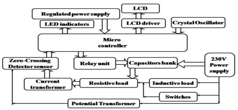
PIC is a own family of Harvard structure microcontrollersmadebyusingMicrochipTechnology, derived from the PIC1640 initially evolved by way of General Instrument's Microelectronics Division. The callPICinitiallynoted"PeripheralInterfaceController".
A PIC's instructions vary from approximately 35 commands for the low give up PICs to over eighty commands for the high end PICs. The instruction set consists of instructions to perform a lot of operations on registers at once, the accumulator and a literal consistentortheaccumulatoranda checkin,aswellas forconditionalexecution,andprogrambranching
Relayis anelectromagnetic transfer. .Itincludes acoil ofcordsurroundingagentleironmiddle,anironyoke, whichgivesalowreluctancecourseformagneticflux,a movable iron armature, and a set, or sets, of contacts; insidetherelaypictured.Thearmatureishingedtothe yoke and routinely linked to a moving contact or contacts. When an electric powered modern day is passed thru the coil, the resulting magnetic subject attracts the armature and the resultant motion of the movable contact or contacts both makes or breaks a referencetoasettouch
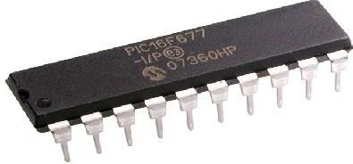
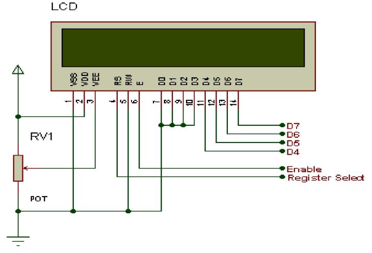
A liquid crystal show (LCD) is a thin, flat digital visual showthatmakesuseofthelightmodulatingresidences of liquid crystals.Liquid crystal display may be very critical device in embedded device. It offers high flexibility to consumer as he can display the specified
© 2022,
e ISSN:2395 0056
p ISSN:2395 0072
facts on it. These are utilized in a wide variety of applications,whichincludespcvideodisplayunits, tv, devicepanels,plane,cockpitdisplays,signage,etc
Pin No. Name Description
Pinno.1 VSS Powersupply(GND)
Pinno.2 VCC Powersupply(+5V)
Pinno.3 VEE Contrastadjust
Pinno.4 RS 0 = Instruction input1 = Data input
Pinno.5 R/W 0=WritetoLCDmodule1=Read fromLCDmodule
Pinno.6 EN Enablesignal
Pinno.7 D0 Databusline0(LSB)
Pinno.8 D1 Databusline1
Pinno.9 D2 Databusline2
Pinno.10 D3 Databusline3
Pinno.11 D4 Databusline4
Pinno.12 D5 Databusline5
Pinno.13 D6 Databusline6
Pinno.14 D7 Databusline7(MSB)
Impact Factor value: 7.529
9001:2008
International Research Journal of Engineering and Technology (IRJET)
Volume: 09 Issue: 05 | May 2022 www.irjet.net
Zero crossing detection is the manner of locating the variantof waveform from 0asreference point. Inthis mission that is used to discover whether or not each contemporary and voltage wave paperwork are main orlaggingorinsegmentwitheachother.
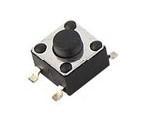
Reset is used for placing the microcontroller into a 'regarded' circumstance. That nearly way that microcontroller can behave as an alternative inaccurately beneath sure undesirable situations. In order to maintain its proper functioning it must be reset.Aswitchplacedamongthevirtualinputandfloor willshortthedigital entertofloorwhilstitispressed. This means the voltage seen at the input may be excessivewhentheswitchisopenandcoffeewhilethe switchisclosed
e ISSN:2395 0056
p ISSN:2395 0072
LED (Light Emitting Diode) is a semiconductor mild sourceusedasanindicator.Inthechallenge,LEDsigns areusedtoshowtheMicrocontrollerhealthStatusand indicationsfor numerousoperationsLEDs used inthe undertakingworkswith2V,10Ma
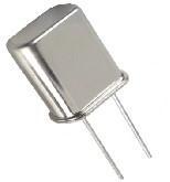
An digital oscillator is an electronic circuit that produces a repetitive Electronic sign, frequentlya sine wave or a rectangular wave.PIC micro controller internally having 4mhz clock frequency. We are giving the 20Mhz clock frequency as an outside source for growing thedeviceperformance.
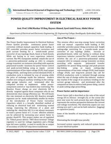
The schematic diagram explains the interfacing segment of every component with micro controller, LCDandrelaymodule.Thecrystaloscillatorconnected to thirteenth and 14th pins of micro controller and controlled strength supply is also related to micro controller and LED’s additionally linked to micro controllerviaresistorsandmotormotiveforcerelated to micro controller. This circuit consists of DC electricity supply unit, zero voltage crossing detectors, Micro controller, LCD display, Relays and Capacitor financial institution and Load circuit. Let us see the way it operates. The required DC energy deliver for Micro controlleranddifferentperipheralsisfurnished by the DC energy supply For the calculation of the power element by the Micro controller we need digitized voltage and current indicators. The voltage signalfromthemainsis takenandit'smilesconverted into pulsatingDCbyusingbridge rectifierandisgiven to comparator which generates the digital voltage signal. Similarly the contemporary signal is converted into the voltage sign via taking the voltage drop of the loadmodern dayacrossaresistorof10ohms.ThisA.C signal is once more converted into the virtual sign as completed for the voltage signal. Then these digitized voltage and modern day signals are despatched to the micro controller. The micro controller calculates the timedistinctionamongthe0crossingpointsofpresent dayandvoltage,whichiswithoutdelayproportionalto the strength aspect and it determines the range wherein the strength issue is. Micro controller sends statistics regarding time distinction between contemporaryandvoltageandstrengthelementtothe LCD show to display them, Depending on the range it sends the signals to the relays thru the relay driving force. Then the desired wide variety of capacitors is connected in parallel to the weight. By this the power aspectcouldbeimproved
International Research Journal of Engineering and Technology (IRJET) e ISSN:2395 0056
Volume: 09 Issue: 05 | May 2022 www.irjet.net
ThekWcapacityoftheprimemoversisbetterutilized. Thisincreasesthekilowattcapacityofthealternators.
The kW capacity of transmission and the lines are accelerated
Theefficiencyofeveryplantisincreased.
Theordinarypriceinkeepingwithunitreduced
Theregulationofthelinesissteppedforward
Fastresponse.
Efficientandlowcostdesign.
Lowpowerintake.
Applications
1.Canbeusedtoallloadstoimprovethepowerfactor.
2.Canbeusedforindustrialloads
Integrating capabilities of all the hardware additives used had been developed in it. Presence of every module has been reasoned out and located carefully, forthatreasoncontributingtothefirst classoperating of the unit. Secondly, the usage of especially advanced IC’s with the help of developing era, the undertaking hasbeeneffectivelyapplied.Thusthemissionhasbeen efficaciouslydesignedandtested.So,throughtheusage of the Automatic Power Factor Improvement module we can efficaciously enhance the power factor for variable inductive hundreds, enhancing the existence spanof deviceandloweringelectricitypayments.
1.G.Raimondo,P.Ladoux,A.Lowinsky,H.Caron,and P. Marino, “Reactive power compensation in railways based on AC boost choppers,” IET Electr. Syst. Transp.,vol.2,no.4,pp.169 177,Jua.2012.
value: 7.529
p ISSN:2395 0072
2. S. Gazafrudi, A. Langerudy, E. Fuchs, and K. Al Haddad, “Power quality issues in railway electrification:acomprehensiveperspective,” IEEE IEEE Trans. Ind. Electron., vol. 62, no. 5, pp. 3081 3090,May.2015