International Research Journal of Engineering and Technology (IRJET)

Volume: 09 Issue: 04 | Apr 2022
e ISSN:2395 0056
p ISSN:2395 0072
International Research Journal of Engineering and Technology (IRJET)
Volume: 09 Issue: 04 | Apr 2022
e ISSN:2395 0056
p ISSN:2395 0072
1Associate Prof., 2Assistant Prof., 3Assistant Prof. Department of Electrical and Electronics Engineering, ATME College of Engineering, Mysuru, Karnataka, India
Electric vehicles will reduce greenhouse gas emissions while simultaneously reducing petrol prices. A variety of charging networks must be built in a user friendly environment to boost the adoption of electric vehicles. WEVCS (Wireless Electric Vehicle Charging Systems) may be a feasible alternative to using a plug to charge electric vehicles. This paper describes the present state of wireless power transfer technologies for electric vehicles. WEVCS have been related to health and safety problems, which have been investigated in connection to the development of current international standards. The static and dynamic WEVCS applications are reviewed, as well as current advancements with features from universities, research laboratories, and industry. Furthermore, future concept based WEVCS, such as "Vehicle to Grid (V2G)" and "in wheel" WirelessChargingSystems(WCS),arereviewedandexamined,withqualitativecomparisonstootherexistingtechnology.
The transportation industry is a major contributor to global climate change and CO2 emissions [1]. With transportation accountingforalmost60%ofglobaloilusagein2017,thedemandforacleanalternativeisurgent[2].Electricvehicles(EVs) areacriticalcomponentinthetransitiontoacleanenergycivilization[3].EVshavebeenadvancedtremendouslyintermsof performanceandrange.Variousmodelsarecommerciallyavailableonthecurrentautomotivemarket. Witha risingnumber of EVs on the road, determining how to charge them properly and efficiently remains a challenge, having a substantial influence on power networks [4], [5]. Almost majority of the existing EVs are charged by electric cables. Cables must be physically linked to the EVs for charging, whether at home or on the roadway. These strong connections might be quite dangerous,especiallyininclementweather.Furthermore,theymayproducesparkingwhenpluggedinandunplugged,which severelylimitstheusageofEVsinsomesituations,suchasnearpetrolstationsandairports.Wirelesscharging,whichismore versatile and convenient, has gotten a lot of attention. Several firms, including Tesla, BMW, and Nissan, have begun to build wirelesslychargedelectricvehiclesthatdonotrequirecumbersomeconnections.Thewireless(inductive)link,ratherthana physical cable connection, successfully prevents sparking. Wireless charging also gives up new opportunities for dynamic charging,suchaschargingwhiledriving.
In high power applications, such as EVs [6] and plug in electric vehicles (PEVs) [7] in stationary [8] applications, Wireless ChargingSystems(WCS)havebeensuggested.WCScanprovidemorebenefitsintermsofsimplicity,dependability,anduser friendliness than plugin charging solutions [9]. WCS have an issue or restriction in that they can only be used when the automobileisparkedorinstationarymodes,suchasatparkinglots,garages,orattrafficlights.Furthermore,stationary WCS have a number of obstacles, including EMC concerns, restricted power transmission, bulky constructions, shorter range, and greaterefficiency[10 12].ThedynamicmodeofoperationoftheWCSforEVshasbeeninvestigatedinordertoincreasethe two areas of range and sufficient battery storage volume [13,14]. This technology enables battery storage devices to be chargedwhilethevehicleisinmotion.
Thevehicle usesless expensive batterystorage spaceandhasa longerrange of travel [15]. However, before beinggenerally accepted,adynamicWCSmustovercometwomajorobstacles:asignificantairgapandcoilmisalignment.Thecoilalignment andair gapdistancebetweenthesourceandreceiveraffectpowertransferefficiency[10,16].Forcompactpassengervehicles, the usual air gap distance ranges from 150 to 300 mm, whereas it may grow for bigger vehicles. Because the automobile is driven automatically in dynamic mode, aligning the ideal driving position on the transmitter coil is simple. On both the transmitting and receiving sides, several compensation strategies, such as series and parallel combinations, are used to decreaseparasiticlossesandincreasesystemefficiency[17,18].ThefundamentalfunctioningofWCSforEVs,includingpower
1Raghavendra L, 2Sathish K R, 3 Priyadarshini L
International Research Journal of Engineering and Technology (IRJET)
Volume: 09 Issue: 04 | Apr 2022 www.irjet.net
e ISSN:2395 0056
p ISSN:2395 0072
transfermechanisms,isexaminedinthisreviewstudy.Inordertooptimizepowertransmissionefficiency,arangeofwireless transformer architectures are also discussed. Current advances in the dynamic and static modes of WEVCS in both the corporateandacademicsectorsarealsodiscussedinthispaper.
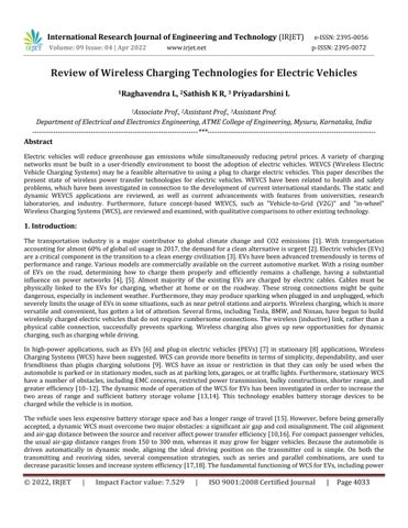
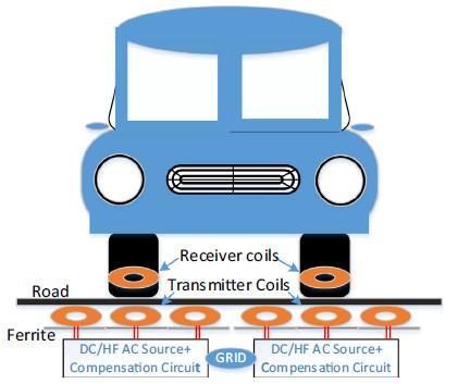
Figure 1 shows the fundamental block diagram of the static WCS for EVs. AC mains from the grid are transformed into high frequency(HF)ACusingAC/DCandDC/ACconverterstofacilitatepowertransferfromthetransmissioncoiltothereception coil. On both the transmitting and receiving sides, compensatory topologies based on series and parallel combinations are usedtoincreaseoverallsystemefficiency[19,20].TheoscillatingmagneticfluxfieldsareconvertedtoHFACbythereceiving coil,whichisusuallypositionedbelowthecar.TheHFACisthenconvertedtoasteadyDCsupplythattheon boardbatteries can utilize. To avoid any health and safety issues and to assure steady operation, the power control, communications, and battery management system (BMS) are also integrated. To eliminate any harmful leakage fluxes and enhance magnetic flux distribution,magneticplanarferriteplatesareusedonboththetransmitterandreceiversides.
WEVCSprovideanumberofbenefitsovertraditionalplug inchargingdevices.Itdoes,however,comewiththreemainhealth andsafetyconcerns:electrical,magnetic,andfirehazards.WEVCSisahigh current,high voltagesystem.Thismightresultin anelectricalshockhazardifthegadgetmalfunctionsorisaccidentallydamagedasaconsequenceofenvironmentalconditions (hot or cold) or physical damage. Furthermore, level 1 (3.7 kW) and level 2 (7.7 kW) WEVCS are commonly seen in homes, dormitories, and general parking places, with transmitter charging pads embedded in the ground or concrete. To give protectionandavoidanylife threateningscenarios,thistypeofsetupneedsadditionalsafetyregulations.
Magnetic fluxes produced at high power levels may exceed the minimal requirements and limits established by standards authorities, posing a risk to the general public. Electromagnetic compatibility (EMC) and electromagnetic interference (EMI) mustbeinvestigatedtoaddressthechallengeoftechnologicalsafetyfeaturesinordertosafeguardthesurroundingplantsand animals. Furthermore, strong power transmission from the transmitter to the receiver's charging pads occurs over huge air gapsrangingfrom150mmto300mmandatfrequenciesrangingfromafewkilohertztoafewmegahertz. Asaresultofthe enormousairgaps,highfrequencyleakagefluxesaregenerated. Theamountofsuchexposurefluxesmustbebeloworsatisfy thehumanexposurelimits(IEEEC.95.12005,Forarangeofhumanbodyparts,seeICNIRP1998(0Hz 300GHz)andICNIRP 2010(0Hz 100kHz)[21].Maximumpermissibleexposure(MPE)andspecificabsorptionratio(SAR)havebeenusedtodefine appropriatelimits[22].Ifapersonwithhealthmonitoringequipment,suchasapacemaker,isexposedtoleakagefluxes,they may experience health problems. This may happen if you're sitting in the car when it's wireless, or if you're walking or standing near the wireless charging pads. The influence of EMC and EMI concerns on a range of magnetic ferrite forms has
Factor value:
International Research Journal of Engineering and Technology (IRJET)
Volume: 09 Issue: 04 | Apr 2022 www.irjet.net
e ISSN:2395 0056
p ISSN:2395 0072
beenverifiedusingFEMsimulationtotacklesuchproblems[23].Furthermore,severalcontinuingresearchanddevelopment prototypeshavebeenbuiltandtestedtomaketheWEVCSmoreuser friendly.
It is important to specify standards for power level, efficiency, operating frequency, EMC, EMI, safety and testing for the research and commercialization of the WEVCS in order to provide a user friendly environment for the technology. Many international organisation and task forces, including the Society of Automotive Engineers (SAE), the International Electro Technical Commission(IEC), theInstituteofElectrical andElectronicsEngineers(IEEE) andUnderwritersLaboratories(UL) have been collaborating with universities, governments, institutes, and the EV industry to enable commercialization. Regarding EMF limits, EMC levels, and compatibility with health monitoring medical implanted devices like pacemakers, the International Commission on Non Ionizing Radiation Protection (ICNIRP), Federal Communications Commission (FCC), and AmericanAssociationofMedicalInstrumentation(AAMI)basedelectromagneticsocietiesarereferredto[24].It'sunfortunate thatfeaturesofstandardsandinteroperabilityhaven'tbeenfullyestablishedbecausetherearesomesubstantialroadblocks to thistechnology'sapplication.
DespitethefactthatWEVCS providemore benefitsthan plug inchargers,obstacleslikeashealthandsafety,budgets,power rangelimits,infrastructuredevelopment,andmaintenancemustbesolvedbeforedeploymentcantakeplace.Sections2.2and 2.3, respectively, have highlighted health and safety problems such as EMC, fire, and electrical dangers with the recent developmentofthestandards.ThepowerrangelimitsoftheWEVCS,ascomparedtoplug inchargers,isanotherkeybarrier towidespreadacceptability.TheACLevel1(1.4 1.9kW)and2(3.3 20kW)on boardchargingsystemshaveachargingrange of 2 20 miles per hour. In 20 minutes, DC rapid charging (up to 100 kW) may provide 60 to 80 miles of range [26 28]. AccordingtothenewJ2954specifications,WPTclassesforstaticmodecangoupto22kW.They'restillintheearlystages of research and development. To address these challenges, a sophisticated network of static and dynamic wireless charging stationsmustbeinstalledonthehighways.Duetoincompatibilitywithpresentarrangements,suchanetworknecessitatesthe building of new infrastructure. Because the beginning cost of WEVCS Level 1 (3.3 kW) might be around $2470 [25], this can resultinincreasedfinancialobligationsforgovernmentalorganisation.
Withachargingpowerlevelof200kW,thedynamicWCScancostuptoA$2M/km/lane[29].Foremergingandpoornations, thisisexpensive.Becausethebuildingissucha largeinvestment,goodmaintenanceisessentialtoavoidseverelossesdueto incorrect handling, wear and tear, and limits of foreign object identification (FOI) [30]. Overall, a number of experimental using simulation scenarios based techniques are offered to build user friendly international standards that can assure worldwideuniformityinordertoeffectivelydeployWEVCS.
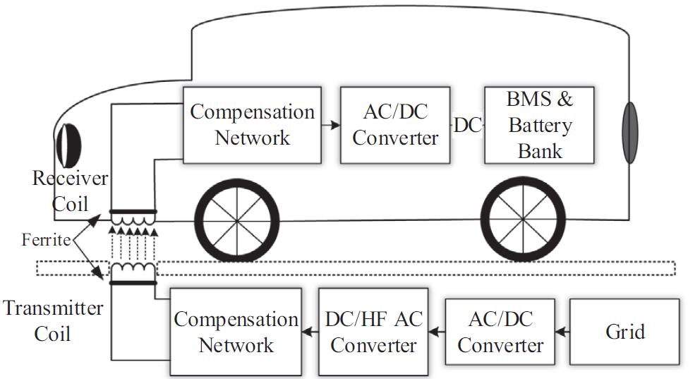
TherapidgrowthofPEVshasnecessitatedthedevelopmentofquickandefficientchargingandpowertransfertechniques.As thenumberofPEVsgrows, sodoesthedemandforelectricityfromdistributionnetworks,whichhasa negative influenceon them. Renewable energy sources (RES) have been introduced to the microgrid to compensate for the increased power demand,although theyhavelimitedsupportfacilities.Thevehicle to grid(V2G) ideacanprovideasolutionforchargingand dischargingtothedistributionnetwork,aswellasimprovedscheduling[8].Thebi directionalpowertransmissionapplication forPEVswithwirelessandplug InmodesisshowninFigure2.EVswithanon boardbi directionalchargerintheplug InV2G modeallowtheusertoconnecttothegridortotheirhouseatpeakhours. ThecarischargedfromanACwallsocketduring off peak hours. To ensure additional protection to the user, AC is converted through DC and supplied to an isolated DC/DC converter. BMS, control and protection, and a bi directional DC/DC converter are used to send converted DC to a battery. When charging the battery bank, this converter acts in buck (step down mode), and when discharging, it operates in boost mode (in order to increase power level). Figure 2 illustrates this (b). The disadvantage of this method is that it necessitates physicalcontactandhumanhandlingtochargeordischargetheelectricvehicles,whichintroducesextrariskssuchaselectric shockandtriphazards.Toaddresstheseissues,awirelessV2Ghasbeendeveloped,asillustratedinFig.2.(a).
© 2022, IRJET | Impact Factor value: 7.529 | ISO 9001:2008 Certified Journal | Page4035
International Research Journal of Engineering and Technology (IRJET)
Volume: 09 Issue: 04 | Apr 2022 www.irjet.net
e ISSN:2395 0056
p ISSN:2395 0072
Fig. 2. Bidirectional power transfer applications (a) wireless V2G (b) plug In V2G.
The comparison between wireless V2G and plug in V2G is shown in Table 1. Unlike plug in V2G, the primary side of the wireless transformer is integrated with bidirectional power converters on the road or parking surface. The receiver coil is positioned beneath the vehicle, while the remaining bi directional power converters are mounted in the body. The design is self contained and uses a wireless transformer to offer further isolation between the source and receiver sides. In static or dynamic modes, surplus energy can be sent to PEVs to relieve stress or received energy to rectify peak demand energy. Furthermore,inadynamicV2Goperation,thistechnologycanserveasabufferorbackupformobileenergystorage.
Table.1: Comparison between Plug-In V2G and Wireless V2G
Features
Plug-In V2G Wireless V2G
Method TraditionalConductive WirelessPowerTransfer
Convenience Medium VeryHigh
PowerTransferEfficiency >90% >90%
PowerTransferCapability High High
PositionSensitivity N/A MediumtoHigh
ConnectionCompatibility Varietyofstandardsshapesandsizes NoPlugs
HealthandSafety: Isolation
ElectricShockHazard
EMI
Compulsoryon boardtransformer Mediumtohigh Low
WirelessTransformer Lowtomedium Mediumtohigh
Air gapSensitivity N/A MediumtoHigh
Operatingfrequency 16 100kHz 81.9 90kHz
OperatingFunction Manual Automatic
PowerTransferScheduling Manual Automatic
International Research Journal of Engineering and Technology (IRJET)
Volume: 09 Issue: 04 | Apr 2022 www.irjet.net
e ISSN:2395 0056
p ISSN:2395 0072
EMC issues, limited power transmission, bulky constructions, and improved efficiency are among obstacles that stationary WEVCSconfront[6,31,32].Additionally,thecoilalignmentandair gapdistancebetweenthesourceandreceiveraffectpower transferefficiency[31,33].Forcompactpassengervehicles,theusualair gapdistancerangesfrom150to300mm,whereasit maygrowforbiggervehicles.Thealignmentproblemcanbehandledwiththeuseofsensortechnologyorparkingassistance, which can direct the driver to the coil's centre. Before becoming more generally adopted, Dynamic WEVCS technology must overcome two major obstacles: a huge air gap and coil misalignment. The misalignment problem can be overcome to some extent due to the large number of source coils. In wheel WCS (IW WCS) has been developed for stationary and dynamic applications to address air gap issues in the WEVCS. It is also less dependent on receiving coil shape and placement standardization,asshowninresearchpublications[17,34 36].IW WCS,bothstaticanddynamic,arefuturetechnologiesthat maybeutilizedtochargeEVsorPHEVswhilestationaryormoving.IW WCSprovidessubstantialbenefitsoverexistingquasi dynamicordynamic WCSduetodecreasedair gapsandgreatercouplingefficiencybetweenthetransmitterandreceiver.The multiplesourceorsourcecoils,likeotherWEVCS,areusuallypositionedbeneaththeroadsurface.
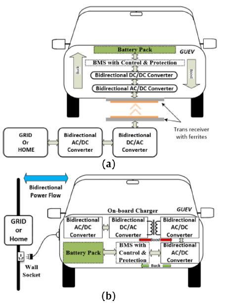
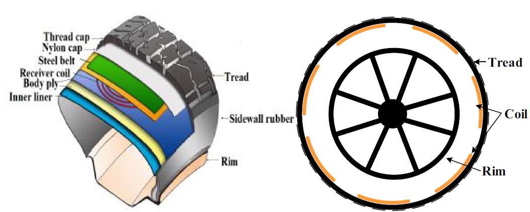
Figure3showstheIW WCSbasicschematicdiagramforstationaryanddynamicapplications.Acompensatingcircuitconnects theprimarywindingstothemaingridsource,whichistransformedtoahighfrequency(HF)ACsource.Thesecondarycoilsof the IW WCS are integrated into the tyre construction, unlike other WEVCS. In compared to conventional static or dynamic WEVCS, the air gap between the source and receiver coils in an IW WCS is lower. The wireless transformer coils, power supply, and internal structure of the tyre are the three primary structural components of an IW WCS, all of which must be properlybuiltinordertocreateanefficientstaticanddynamicIW WCS.Figure4showsadetailedinternalpositioningofthe
International Research Journal of Engineering and Technology (IRJET)
Volume: 09 Issue: 04 | Apr 2022 www.irjet.net
e ISSN:2395 0056
p ISSN:2395 0072
receiver coils. Inside the tyre, many receiver coils are arranged in a parallel configuration. The benefit of this design is that only the receiver coil that is in touch with the transmitter is activated. Multiple receiver coils may be triggered in some circumstanceswhenhorizontalmisalignmentoccurs.Thesearethedevicesthatdeliverelectricitytothebatterybankorload. A resonant capacitor, rectifier, and filtering circuits are all included in each receiver coil. The receiver coils array should be placedbetweenthesteelbeltandthebodyply.
This work presents a foundational description of the WEVCS for fixed and dynamic applications using present research methods. Concerns about health and safety have been raised, and current global standards improvements have been presentedtoWEVCS.Withstate of the artstationaryanddynamicWEVCS,presentresearchanddevelopmentfromarangeof governmental and commercial organizations has been analyzed and summarized. Finally, future technologies that are emergingareevaluated.ThemostpresentbreakthroughsinthefieldofWEVCSarediscussedinthisarticle.
1. InternationalEnergyAgency(IEA),"GlobalEnergy&CO2StatusReport2017,"IEA,2018.
2. "BPEnergyOutlook2017,"2017.[Online].
3. N.Adnan,S.M.Nordin,I.Rahman,P.VasantandM.A.Noor,“Anoverviewofelectric vehicletechnology:a visiontowards sustainabletransportation”,IntelligentTransportationandPlanning:BreakthroughsinResearchandPractice,2018.
4. S.SachanandN.Adnan,“Stochasticchargingofelectricvehiclesinsmartpowerdistributiongrids”,SustainableCitiesand Society,Vol.40,pp.91 100,2018.
5. N. Adnan, S. M. Nordin and O. Althawadi, “Barriers towards widespread adoption of V2G technology in smart grid environment:fromlaboratoriestocommercialization”,SustainableInterdependentNetworks,pp.121 134,2018.
6. K.A. Kalwar, M. Aamir, S. Mekhilef, Inductively coupled power transfer (ICPT) for electric vehicle charging a review, Renew.Sustain.EnergyRev.47(2015)462 475.
7. G. Ombach, Design considerations for wireless charging system for electric and plug in hybrid vehicles, Hybrid Electr. VehiclesConf.2013(2013)1 4.
8. D.Leskarac,C.Panchal,S.Stegen,J.Lu,PEVChargingTechnologiesandV2GonDistributedSystemsandUtilityInterfaces, in: J. Lu, J. Hossain (Eds.), Vehicle to Grid: Linking Electric Vehicles to the Smart Grid, The Institution of Engineering and Technology(IET),London,UnitedKingdom,2015,pp.157 209.
9. H. Barth, M. Jung, M. Braun, B. Schmülling, U. Reker, ‘‘Concept Evaluation of an Inductive Charging System for Electric Vehicles”,Presentedatthe3rd EuropeanConferenceSmartGridsandE Mobility,Munchen,Germany,2011.
10. M. SangCheol, K. Bong Chul, C. Shin Young, A. Chi Hyung, M. Gun Woo, Analysis and design of a wireless power transfer systemwithanintermediatecoilforhighefficiency,Indust.Electr.,IEEETrans.61(2014)5861 5870.
11. G.A.Covic,J.T.Boys,Inductivepowertransfer,Proc.IEEE101(2013)1276 1289
12. G.A. Covic, J.T. Boys, Modern trends in inductive power transfer for transportation applications. Emerging and selected topicsinpowerelectronics,IEEEJ.1(2013)28 41.
13. S. Lukic, Z. Pantic, Cutting the cord: static and dynamic inductive wireless charging of electric vehicles, Electr. Magazine, IEEE1(2013)57 64.
International Research Journal of Engineering and Technology (IRJET) e ISSN:2395 0056 Volume: 09 Issue: 04 | Apr 2022 www.irjet.net p ISSN:2395 0072
14. M. Eghtesadi, Inductive Power Transfer to an Electric Vehicle Analytical Model, Vehicular Technology Conference, 1990 IEEE40th,1990,pp.100 104.
15. M.Fuller,WirelesscharginginCalifornia:range,recharge,andvehicleelectrification,Trans.Res.PartC:Emerg.Technol.67 (2016)343 356.
16. F.vanderPijl,P.Bauer,M.Castilla,Controlmethodforwirelessinductiveenergytransfersystemswithrelativelylargeair gap,Industr.Electr.,IEEETrans.60(2013)382 390.
17. Q. Zhu, L. Wang, C. Liao, Compensate capacitor optimization for kilowatt level magnetically resonant wireless charging system,Indust.Electr.,IEEETrans.(2014).
18. K. Jinwook, K. Do Hyeon, P. Young Jin, Analysis of capacitive impedance matching networks for simultaneous wireless powertransfertomultipledevices,Indust.Electr.,IEEETrans.62(2015)2807 2813.
19. J.L. Villa, J. Sallan, J.F.S. Osorio, A. Llombart, High misalignment tolerant compensation topology For ICPT Systems, IEEE Trans.Indust.Electr.59(2012)945 951.
20. K.Kalwar,S.Mekhilef,M.Seyedmahmoudian,B.Horan,Coildesignforhighmisalignmenttolerantinductivepowertransfer systemforEVcharging,Energies9(2016)937.
21. (1998,April)Guidelinesforlimitingexposuretotime varyingelectric,magnetic,andelectromagneticfields.HealthPhysics.
22. R.Bashirullah,Wirelessimplants,IEEEMicrowaveMag.11(2010)S14 S23.
23. C.Panchal,D.Leskarac,J.Lu,S.Stegen,InvestigationoffluxleakagesandEMCproblemsinwirelesschargingsystemsforEV andothermobileapplications,Environ.Electromagnet.(CEEM),20126thAsia PacificConf.(2012)301 304.
24. J.Schneider,DevelopmentsinWirelessPowerTransferStandardsandRegulations,IEEEStand.Educ.eMagaz.98(2016).
25. (2017,27February).PluglessPower.Available:https://www.pluglesspower.com/shop/
26. H. L. Chen. (2016, 27 February). Optocouplers Help Promote Safe, Efficient EV Charging Stations. Available: http://electronicdesign.com/power/optocouplers help promote safe efficient ev charging stations.
27. T.Bohn.(2013,27February).PEVChargingStandardsStatusIncludingAC,DCandWirelessTechnologies.
28. B.Berman.(2014,27February).ElectricVehicleChargingforBusinesses.
29. A.Shekhar,V.Prasanth,P.Bauer,M.Bolech,Economicviabilitystudyofanon roadwirelesschargingsystemwithageneric drivingrangeestimationmethod,Energies9(2016)76.
30. Vatsala, R. Hasan Khan, Y. Varshney, and A. Ahmad, Challenges and Potential Solutions for the Deployment of Wireless ChargingInfrastructureforxEVsinIndia,2017.
31. C. Liu, A.P. Hu, B. Wang, N.K.C. Nair, A capacitively coupled contactless matrix charging platform with soft switched transformercontrol,IEEETrans.Indust.Electr.60(2013)249 260.
32. J. Dai, D.C. Ludois, ‘‘Wireless electric vehicle charging via capacitive power transfer through a conformal bumper”, IEEE Appl.PowerElectr.Conf.Expos.(APEC)2015(2015)3307 3313.
Factor value:
International Research Journal of Engineering and Technology (IRJET) e ISSN:2395 0056
Volume: 09 Issue: 04 | Apr 2022 www.irjet.net p ISSN:2395 0072
33. A.P. Hu, C. Liu, H.L. Li, A Novel Contactless Battery Charging System for Soccer Playing Robot, 2008 15th International ConferenceonMechatronicsandMachineVisioninPractice,2008,pp.646 650.
34. W. Li, High Frequency Wireless Power Transmission at low Frequency using Permanent Magnet Coupling Thesis, Master AppliedScience,Vancouver,2007.
35. C. Qiu, K.T. Chau, C. Liu, C.C. Chan, Overview of wireless power transfer for electric vehicle charging, 2013 World Electric VehicleSymposiumandExhibition(EVS27),2013,pp.1 9.
36. K.W.Klontz,A.Esser,R.R.Bacon,D.M.Divan,D.W.Novotny,R.D.Lorenz,Anelectricvehiclechargingsystemwith’universal’ inductiveinterface,Conf.Rec.PowerConv.Conf. Yokohama1993,227 232.
RaghavendraL
AssociateProfessor DepartmentofEEE
ATMECollegeofEngineering,Mysuru,Karnataka.
Dr.SathishKR
AssistantProfessor DepartmentofEEE
ATMECollegeofEngineering,Mysuru,Karnataka.
PriyadarshiniL AssistantProfessor DepartmentofEEE


ATMECollegeofEngineering,Mysuru,Karnataka.
Impact Factor value: 7.529