International Research Journal of Engineering and Technology (IRJET)

Volume: 09 Issue: 04 | Apr 2022 www.irjet.net
e ISSN: 2395 0056
p ISSN: 2395 0072
Comparative Analysis of an RC framed building under Seismic Conditions.
1,2,3B.Tech Student, Dept. of Civil Engineering, Delhi Technological University, Delhi, India 4Professor, Dept. of Civil Engineering, Delhi Technological University, Delhi, India
***
Abstract India has suffered four great earthquakes of magnitudes 8.5 and greater, in the past hundred years yet human memory being short, it is generallynot recognizedthat we continue to live under the long shadow of such future calamities. Due to Improper design of the structure without seismic resistance many buildings have collapsed and lives have lost during earthquakes. . Different shapes andmaterials of buildings have been used to achievethestrengthrequired to withstand the earthquake. In modern era, lots of seismic force resisting techniques are being used to make a structure/building earthquake resistant. These techniques include introducing Shear walls, Bracings, base isolation, column jacketing etc. to enhance the structure. We discussthe work done by various authors on Different typeofFailuresdue to Earthquake along with the Design andAnalysisofStructure in Earthquake prone Area and present a Comparativeanalysis of earthquake resisting techniques on a G+10 story building with the help of different types of Shear walls & Bracings, using software. The comparison is done between: an un Resisting structure, parallel shear walls, corner shear wall, X shaped bracing at bracings at middle bays, X shaped bracings at corners and X shaped bracings in whole structure. The use of shear walls and bracings helps to strengthen the structure to make it more Earthquake resistant. The analysis in done on a G+10 building for Delhi region as per IS 1893:2016 provisions. The software that we have used to carry out this analysis is Staad pro v8.
Key Words: Static Analysis, Comparative Analysis, STAAD pro, Shear Wall, Bracing, Seismic Conditions, Earthquake.
1. INTRODUCTION
Fromthehistoryofearth,Earthquakeissuddenviolent shakingorVibrationsoftheground.Earthquakecausedby tectonicmovementinearthCrustandalsocausedbysudden sliponafaultorruptureofgeologicalfaults,Butalsobyother events(natural&artificialcauses)suchasvolcanicactivity, Landslides,mineblastsandnuclear tests.Inrecentstudies geologistclaimthatglobalwarmingisoneoftheReasonfor seismicactivity.Accordingtothesestudiesmeltingglaciers andRisingsealeveldisturbthebalanceofpressureonearth tectonic plates thus causing increase in frequency and intensity ofearthquakes results in Damages structure & propertyofnation. Hence, earthquake is amajorproblem
2022, IRJET | Impact Factor value: 7.529
by development of nation & great Challenge for structural engineer to construct building in seismic region (Zones). Hence,structureshouldbeanalyzedforearthquakeforcesto avoidthedamages.GenerallyStructurehavingtwotypesof loadingthatisstaticloadinganddynamicloading.Staticloads are Constant and dynamic loads are change with time. In maximumcivilbuildingsorstructuresonlystaticloadsare consideredanddynamicloads are not calculated because of more complications in calculation. In Indiavarious previousexamplescanbenotedincludingBhuj2005where thousandsoflivesgotsufferedandthousandsofstructures gotdestroyedbecauseofearthquake.Hencetherewasaneed to make the structure earthquake resistant in order to minimize the destruction of structures and human life these various techniques are being implemented on structuretomakethemseismicallyresistantorearthquake resistant. These techniques include addition of various structuralelementslikesharewalls,bracings,baseisolation dampersetc.InthispaperIamdiscussingthecomparative analysisofvariousearthquakeresistanttechniquesona10 story buildingusingsoftware. Inthispapercompletestatic analysisisperformedbyusingSTAAD Prosoftware.
1.1 SEISMIC RESISTANCE TECHNIQUES
Addition of Shear walls: Shear wall isa seismic restraint member used to oppose lateral forces parallel to the wall. Shear wall opposes the loads due to CantileverAction. So, Shear walls are vertical components of the horizontal or lateralforceresisting
Addition of Bracing: Abracedframeisaframeworkusedin structurestoresisthorizontalloads,forexample,windand seismic pressure. They are commonly made ofbasic steel, which when exposed both tension and compression, work efficiently.Thebeamsandcolumnsthatformtheframecarry vertical loads, and the bracing system carries the lateral loads.Theshaftsandsectionsthatstructuretheframeconvey verticalburdens,andthepropping frameworkconveysthe sidelongloads.
ISO 9001:2008
International Research Journal of Engineering and Technology (IRJET)
Volume: 09 Issue: 04 | Apr 2022 www.irjet.net
2. METHEDOLOGY
The methodology worked out to achieve the mentioned objectivesisasfollows:
1. ModelingoftheselectedbuildinginStaadpro.V8i Software.
2. Five models as per the Indian code specification wereprepared.ModelsincludingBareframe,frames withshearwallsandframeswithbracings.
3. Load combinations as per IS 875 part 1 and IS 1893 2016(part10wereappliedandallthemodels analyzed for axial forces, moments, lateral displacements, max shear, storey displacement, storeydriftandgraphicalandtabularrepresentation ofthedataispresented
3. ANALYSIS TECHNIQUES USED ON STAAD PRO.
1. Maxdeflection:Maxdeflectioncanalsobecalledthe Top deflection of the structure. It is themaximum extent to which the structure displaces in X & Z direction under earthquake loads in both perpendiculardirections.
2. Storydrift:Storydisplacementistheabsolutevalue of displacement of the storey underaction of the lateralforces
3. Storyshear:Thedesignseismicforcetobeappliedat eachfloorleveliscalledstoreyshear.
4. MaximumAxialforce:TheAxialForceisgenerally defined as the Force acting along the axis of a member. The maximum axial force is mostly experienced at the base of the structure, at the bottommostcolumns.
4. BUILDING MODELLING.
4.1 General
InthisprojectwemodelledaG+10storeybuildingwith samefloorplanwith4bayshavingsamelengthsof3malong the longitudinal and the transverse directionas shown in figure.Thebuildingsaremodelledusingsoftware STAAD PROV8i.
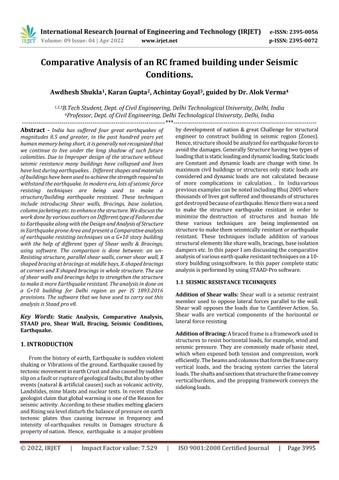
4.2 Input Data
4.3 Loading Details
Dead Load Slab: Thickness assume = 150 mm FloorFinish=75mm
e ISSN: 2395 0056
p ISSN: 2395 0072
Wallloadsexternalwall:230mmthickwallfor 3.0heightsThicknessofwall‘b’ 0.23mHeightof walls‘h’ 3.0m
Unitweightofbrick masonryγ 19.2kN/m3= 0.23 x 3.0 x 19.2 Total load h*b* γ = 13.248 kN/m3
Internalorpartitionwalls:150mmthickwallfor height3.0mThicknessofwall‘b’ 0.12mHeight ofwalls‘h’ 3.0m
Unitweightofbrickmasonry‘γ’ 19.2kN/m3= 0.12 x 3.0 x 19.2 Total load h*b* γ = 6.912 kN/m3
Typeofstructure: multi storey fixed jointed planeframe.
Numberofstories 11(G+10).
Floorheight 3m
Seismiczone IV(DELHI region) (IS 1893 (part1):2016).
MaterialsConcrete (M35)
Reinforcement (Fe415).
Bay sizes in the X direction 3m,3m,3m&3m 4bays
Bay sizes in the Z direction 3m,3m,3m&3m3bays.
Thickness of Wall Externalwall 230mm
Thickness of Internal wall 150mm
Column 450 x 450 mm (for all columns)
Beam 300x300mm(forallbeams).
Typeofsoil mediumsoil
4.4 Load Combination
Theanalysishas beendoneforthedeadload(DL),live load (IL), & earthquakeload(EL) in all the directions i.e. swaytoleft( EL)andswaytoright(EL)byusingsoftware Staadpro.Thecombinationofloadshasbeenmadeaccording tocl6.3ofIS1893(Part1)LoadCombinationforEarthquake Design
Load combinations that are to be used for Limit state Designofreinforcedconcretestructurearelistedbelow.(1) 1.5(DL+LL),(2)1.2(DL+LL±EQ X),(3)1.2(DL+LL±EQ Y),(4)1.5(DL±EQ X),(5)1.5(DL±EQ Y),(6)0.9DL±1.5EQ X,(7)0.9DL±1.5EQ Y.
LiveLoadAllFloor=2kN/m2
© 2022, IRJET | Impact Factor value: 7.529 | ISO 9001:2008 Certified Journal | Page3996
International Research Journal of Engineering and Technology (IRJET)
Volume: 09 Issue: 04 | Apr 2022 www.irjet.net
4.5 Earthquake Loads
LoadsarecalculatedasperIS1893:2016(Part1)Seismic parametersconsideredforanalysisareTable 2:
Table 1: Earthquakeloadtable
Seismic Intensity ZoneIV Zonefactor(Z) 0.24
Response Reduction Factor(R) 5
Importancefactor SoiltypeMediumsoil Damping5%
Thedesignhorizontalseismic coefficient Ah for the structure shall be calculated as follows, (IS:1893 2002,Cl.6.4.2)
5. ANALYSIS
AnalysisofbuildingisoneusingSTAADPro.Themodels werepreparedintheSTADDPro.Softwarebyusingdifferent typesofRCshearwallviz.ParallelShearwallandCornered shearwallandthesearelocatedatdifferentlocationsuchas alongperipheryandatcorner.Andalso,analysisisdoneby modellingstructurewithDiagonalandCrosstypeBracings.
1. BaseStructure(withoutseismicrestraints)Abase structureismodelledonlywiththeuseofcolumns andbeams,andnoadditionalseismicrestraintsare used. This the plain or base structure that will be furtherusedforcomparisonwithothermodelswith additional seismic restraints. The following structureisaG+10storybuildingdesignedonstaad prohavingnoseismicrestraints.
2. ParallelShearWallsModelispreparedusingstaad pro software where the high rise structure is embedded&supportedwithshearwallonallfour sides.Theplandimensionstheshearwallisgivenas (8mx0.200m)fromthebasetotheroofi.e.33m.As theShearwallsareinparalleldirectionwithrespect tothetwodirectionsofearthquakeEQX&EQZ,itis namesasParallelShearwalls.
3. CornerShearWallsModelispreparedusingstaad pro software where the high rise structure is embedded&supportedwithshearwallonallfour Cornersofthebuilding.Theshearwallinstalledhere isaL Shapedshearwallwithplandimensionsgiven as(4mx0.200m)+(4mx0.200m)fromthebaseto theroofi.e.33m.
4. Bracing CrossedModelispreparedusingstaadpro softwarewherethehighrisestructureframeworkis embedded & supported with steel bracings. The
value:
e ISSN: 2395 0056
p ISSN: 2395 0072
steel bracing used is an angle section having dimensions ISA 100x100x12. The bracings are connected diagonally throughout the framework fromonecolumnbeamjointtoanother.
5. Bracing CrossedModelispreparedusingstaadpro softwarewherethehighrisestructureframeworkis embedded & supported with steel bracings. The steel bracing used is an angle section having dimensions ISA 100x100x12. The bracings are connected diagonally at middle portion of the frameworkfromatallsidesoftheframe.
6. Bracing CrossedModelispreparedusingstaadpro softwarewherethehighrisestructureframeworkis embedded & supported with steel bracings. The steel bracing used is an angle section having dimensions ISA 100x100x12. The bracings are connectedatallcornersoftheframework.
7. Combination of bracing and shear wall is used to preparetwomodelsas perconfigurations givenin diagram.
09
04
e ISSN: 2395 0056
p ISSN: 2395 0072
Significantreductioninshearforceisobservedincaseof structureswithXbracingsascomparedtothosewithshear walls. In structures with X bracing the best placement of bracingsamongcornerandmiddleismiddleoftheframeas observedformthegraphabove.CombinationofXbracingat cornerwithshearwallalsoreducestheshearforcebylarge amounts.
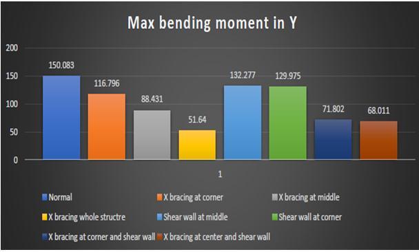
5.3 Axial Force
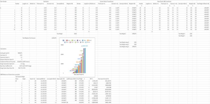
Fig 3:MaxbendingmomentinZ
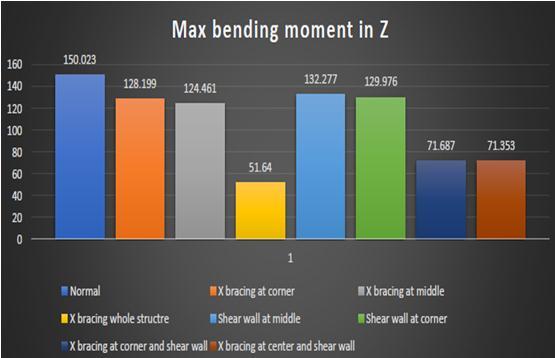
Themaximumreductioninbendingmomentisincaseof bracingandleastincaseofshearwall.Thiscanbeexplained form the fact that shear walls reduce the lateral displacements more as compared to the corresponding bracing structuresasa result larger overturning moments develop in them as compared to structures with bracing. Overallthereisreductioninbendingmomentswithrespect tobareframebutthebestseismicrestraintsinthecaseisX bracing.
5.2 Max Shear Force
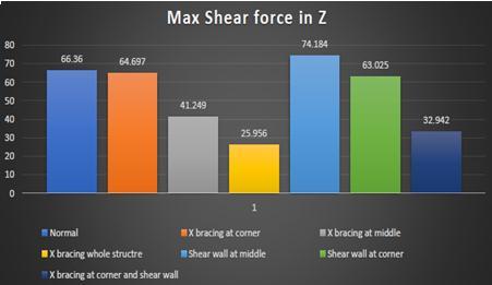
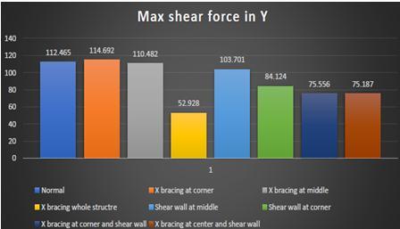
Fig 6:Axialforce
Maxaxialforcerepresenttheaxialforcethroughcolumnsat thebaseofthestructure.. Themaxaxialforceisobservedin themodelwithXbracingsandleastisobservedintheModel withshearwallsignifyingimplyingshearwallsarecapableof reducingaxialforces.
5.4 Base Shear
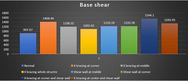
Fig 7:Baseshear
Baseshearisdependentupontheweightofstructurethatis more the weight more is the value of base shear. The minimum value is obtained in case of bear frame while maximumvalueincaseofX bracingatcorner withshear wall.Thetrendshowsthatstructureswithshearwallhave higherbaseshearascomparedtothosewithbracingsdueto moreweightincaseofshearwall.
International Research Journal of Engineering and Technology (IRJET)
Volume: 09 Issue: 04 | Apr 2022 www.irjet.net
5.5 Weight of Structure
Fig 8:Weightofstructure
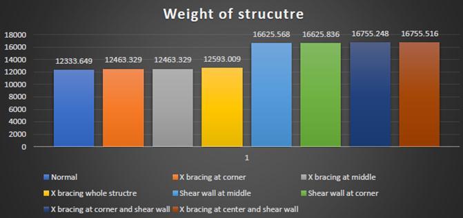
Themaximumincreaseinweightofstructureisobserved incaseofshearwallswhereasincaseofbracingsthereisno significantincreaseinweightofstructurethatagainsignifies that bracing are better seismic restraintsas the give more stabilitywithoutsignificantincreaseinweightofstructure.
6. CONCLUSIONS
1. Eight RC framed models have been observed and analyzed by introducing various earthquake resistingmembers,like:Parallelshearwalls,Corner Shear walls, & Cross Bracings in various configurations.
2. Byprovidingshearwallsandbracingstothehigh risestructure,seismicbehaviourwillbeaffectedtoa greatextentandalsothestiffnessandthestrengthof thebuildingsisincreased.
3. It is found out that shear walls and bracing contribute largely in reducing the deflection by increasingthestrengthandstiffnessofthebuilding. The results of thisproject can further be used to enhance the seismic strength of buildings using combinationofseismicresistancetechniques.
4. It is observed from the above analysis that the displacement observed in the models, which are withoutshearwalls&bracingsismoreascompared to themodels having shear walls and bracings at differentlocations.
5. It has been observed that the Max deflection is significantlyreducedafterprovidingtheshearwalls orbracingsintheRCframeinX directionaswellas inZdirection.
6. The best location of shear wall in multi storey buildingisparallelshearwallsAndthebesttypeof bracingsthatcanbeusediscrossbracingonwhole structure.
e ISSN: 2395 0056
p ISSN: 2395 0072
7. The lateral deflection of column for building with cross bracing on whole structure is reduced maximum followed by those with shear walls as comparedtoallmodels.
8. Finally,itisconcludedthat,optimizationusingcross bracingsisthebestprocedure,inpresentworkmode formaximumearthquakeresistance
9. Shear wall elements are very much efficient in reducinglateraldisplacementofframeasdriftand horizontaldeflectioninducedinshearwallframeare much less than that induced in corresponding braced frame(i.e comparing shear wall at middle with X bracingat middleand shearwall atcorner withXbracingatcorner)andplaneframe.
10. Thecombinationofbareframewithcoupledshear wall in combination with x bracing also provides goodresultaboutreducingthestressesandlateral forcesoverthestructure.Thisimpliesthatthesetype of structure provide better stability during the seismicactivity.
11. Overalltheframescanbearrangedinorderoftheir seismicstability(consideringmoments,storeydrift, storeydisplacementsanddeflections)as
X bracing on whole structure> X bracing at middle with shear wall> X bracing atcorner with shear wall> Shear wall at middle>Shear wall at corner> X bracing at middle> X bracing at corner> Bare frame
REFERENCES
1. Preliminaryreportonseptember28,2004parkfield.
2. EarthquakebyRakesh k. Goel,m.eeri and charles b.Chadwell,m.Eeri,Departmentof civil&environmentalengineering
3. Damageto buildings due to1997umbria marche earthquakem.Dolce,a.Masidisgg,italyuniversityof basilicata gndt
4. Eerispecialearthquakereport september1
5. Geophysicalresearchletters,vol.24,no.9,pages
6. Report of1019 1022, may 1, 1997 on the 1995 colima jalisco, mexico,Earthquake(mw8)
7. A field report by eefit Dr Navin peiris dr tiziana rossetton, Dr paul burton mr suqlain mahmood. Rotation at column and beam junction , column hinging
International Research Journal of Engineering and Technology (IRJET)
Volume: 09 Issue: 04 | Apr 2022 www.irjet.net
8. Learning from earthquakes preliminary observationsonthenovember3,2002denalifault, alaska,earthquake.
9. Hyogoken nanbu(kobe)earthquakeofjanuary17, 1995lifeline
10. Performance byanshel j. Schiff, stanford univ., los altoshills,ca,americansocietyofcivil
11. Kilic, s., sozen, m., 2003, ―evalua tion of effect of august 7, 999, marmara earthquake ontwo tall reinforced concrete chimneys,‖ aci structural journal,vol.00,no.3.
12. Eerispecialearthquakereport july2003,learning fromearthquakes.preliminaryobservationsonthe may1,2003,bingöl,turkey,earthquake
13. Comparative study on seismic analysis of multi storeybuildingstiffenedwithbracingandshearwall. Mohd atif1, prof. Laxmikant vairagade2, vikrant nair3(irjet)
14. Earthquake resisting techniques on a g+10 storey building with the help of shear walls &bracings, usingsoftware.Shahzebkhan,vishalyadav,sandeep singla(ijitee)
15. The response of tall buildings to far field earthquakes and the case of a 49 storey steel building,SifatMuin;AbolhassanAstaneh Asl;Cem Topkaya.
16. Ali,M. M., andK. S.Moon.2007.Structural developmentsintallbuildings:Currenttrendsand futureprospects.
17. Chen,Z. P.,G.Wu,D. C.Feng, andK. J.Ma 2018 Numerical study of the static and dynamic characteristics of reinforced concrete cassettestructuresforhigh risebuildings
Impact Factor value: 7.529
e ISSN: 2395 0056
p ISSN: 2395 0072
9001:2008