International Research Journal of Engineering and Technology (IRJET)

Volume: 09 Issue: 04 | Apr 2022 www.irjet.net
e ISSN: 2395 0056
p ISSN: 2395 0072

International Research Journal of Engineering and Technology (IRJET)
Volume: 09 Issue: 04 | Apr 2022 www.irjet.net
e ISSN: 2395 0056
p ISSN: 2395 0072
 Ambar Shrivastava1 , Anandrao Jaurker2
1 PG Student, Department of Mechanical Engineering, Jabalpur Engineering College, Jabalpur, 482011, Madhya Pradesh, India.
2 Professor, Department of Mechanical Engineering, Jabalpur Engineering College, Jabalpur, 482011, Madhya Pradesh, India
***
Abstract The steering stability, efficiency, convenience, and safety of an automobile are all influenced by the vehicle's aerodynamic properties. A vehicle with minimal drag resistance has an added benefit in value for money and performance. The aerodynamic drag of vehicles can be reduced by employing shape optimization and ADD ON devices. Different types of aerodynamics ADD ON devices (i.e., vortex generators, diffusers, wings, spoilers etc.) are used to reduce the drag of a vehicle. The recent advancement of computationalfluid dynamictechnologyallowspredictingair flows around a vehicle that is exceptionally close to its actual condition.Inthisreviewpaper,Ahmedbodywhichissimplified generic vehicle geometry is reviewed with the application of various aerodynamic devices for drag reduction using the numerical methodology. Square back and Hatchback configuration of Ahmed body with rear slant angles of 0⁰, 25⁰, and 35⁰ are considered in this study.
Key Words: Dragcoefficient,Dragreduction,Computational fluiddynamics,Ahmedbody,Rearslantangles,Aerodynamic ADD ONdevices.
Aerodynamic drag [1] is a force operating in the opposite directionofanyobjectmovingrelativetoair.Twosignificant components of drag force are pressure and skin friction force. Pressure drag dominates ground vehicle aerodynamics,whereasskinfrictiondragdominatesaircraft and marine ships. The basic formula of aerodynamic drag forceisgiveninequation(i).
FAerodynamicDrag = 0.5��d������2 eq.(i)
Where,
��d =CoefficientofDrag
�� =Airdensity(inkg/m3)
�� =Frontalarea(inm2)
�� =Relativevelocityofobjectw.r.t.airmedium(inm/s)
International
Volume: 09 Issue: 04
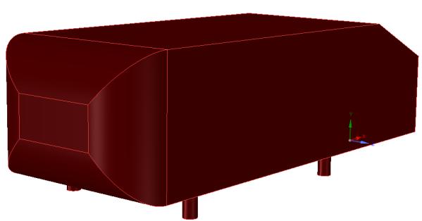
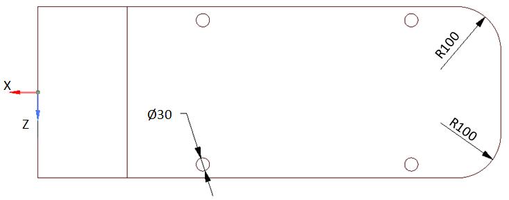
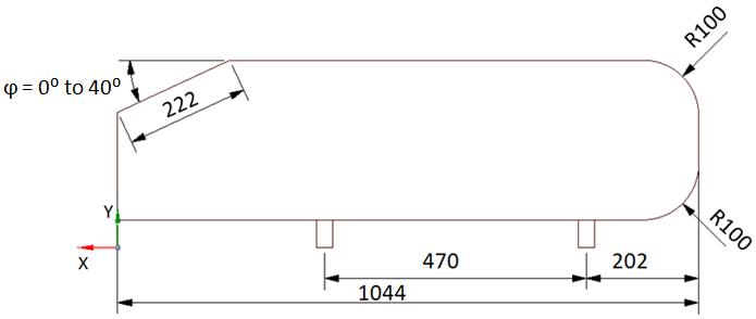
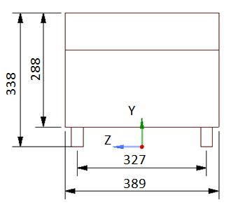
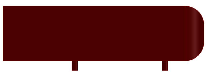
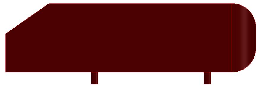
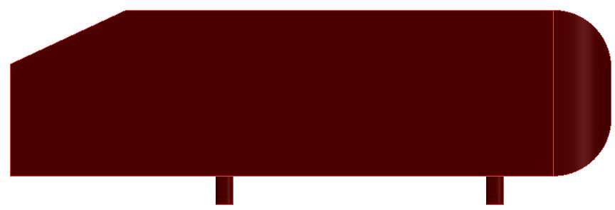
Ahmed Body is a simplified vehicle model, which is a rectangularboxmountedonfourlegswhosefrontedgesare rounded,and the rear slant end is adjustable to study the flow detachment at angles from 0° to 40°. Dimensions of Ahmed body are shown in fig 1. Ahmed body is about a quarterofanactualautomobile(i.e.,hatchback,sedan,and others) whose experimental data are used to validate the actual vehicle's experimental and computational aerodynamicresults. Ahmed et al. (1984)[3] experimentally concluded that the total drag on the Ahmed body was dominated by pressure drag of about 85%, while friction dragaccountedfortheremaining.Furthermore,therearend generatedmostofthepressuredragofabout91%,whilethe frontalportionwasresponsiblefortheremainingdrag.The magnitudeofpressuredraggeneratedattherearendwas highlydependentontheRearSlantAngle(φ).Inthisreview paper, Ahmed body for Square back (with φ = 0°) and Hatchbacks(withφ=25°and35°)areconsideredforthe study. In addition, various types of aerodynamic drag devicesorADD ONsusedinpreviousnumericalstudiesfor the drag reduction of Ahmed body are reviewed in the literaturestudysection.

“Computational fluid dynamics (CFD)” is a branch of continuum mechanics concerned with fluid flow and heat transport issues numerical modeling Core mathematical equations, usually in the partial differential form that governs a process of importance and are referred to as governingequationsinCFD,mayusuallybeutilizedtodefine thephysicalcharacteristicsoffluidmotion Itcombinesnot just fluid mechanics and mathematics but also computer science[4].
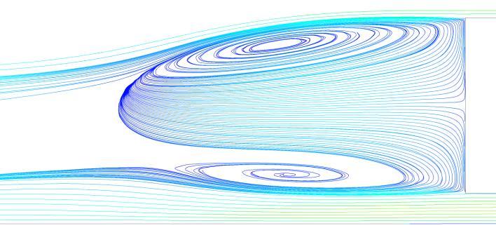
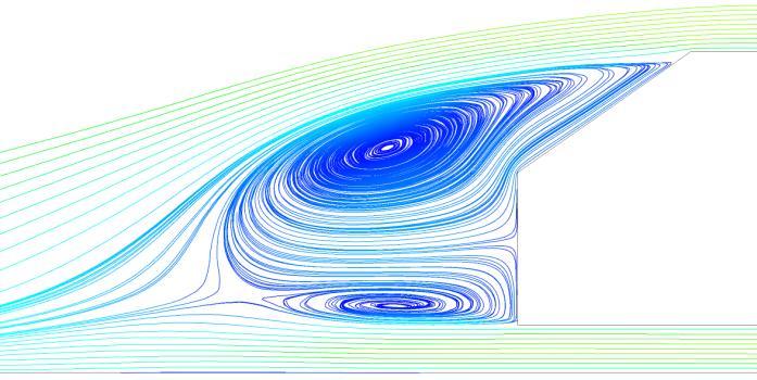
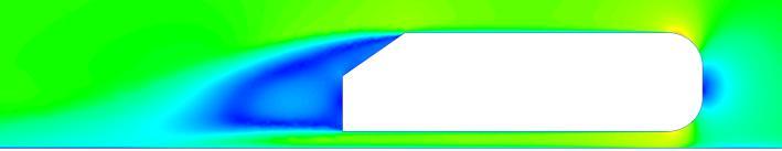
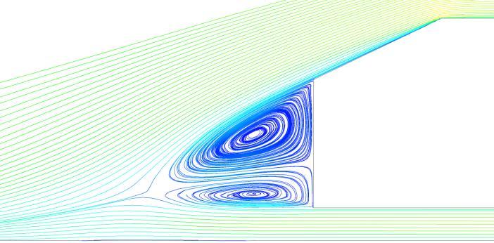
Highlyturbulent,three dimensionalseparationsdefinethe flowaroundvehicles.Asaresult,thedemandforpowerful numerical methods to analyze them rises. CFD based on “Reynolds Averaged Navier Stokes Equations (RANS)”, “LargeEddySimulation(LES)”,andotherturbulencemodels iscommonlyusedintheautomobileindustry.Somewhatof using individual point measurements taken from a wind tunnelinvestigation,CFDgivescontinuousandpreciseflow visualizationofaerodynamiccharacteristicsoverthewhole surface regions of the vehicle [5]. From this information, flowseparation,recirculationbubblescanberetrieved,as showninfig 2,fig 3,andfig 4forAhmedbodywithφ=0°, 25°,and35°,respectively.
Technology (IRJET)
e ISSN: 2395 0056
p ISSN: 2395 0072
(b)Pressurecontours.
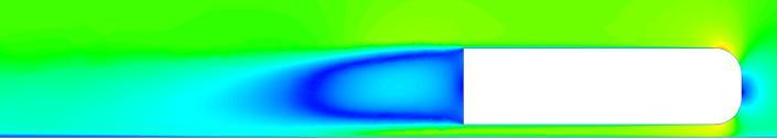
(c)Velocitycontours
(d)VelocitystreamlinesatthewakedownstreamFig 2:CFDflowpredictionsofAhmedbodywithφ=0°.
Fig
Volume:
(a)
e ISSN: 2395
p
(b)Pressure
(c)Velocity
Fig
(d)Velocitystreamlinesat

CFD

International
Journal of Engineering and Technology (IRJET)
Volume: 09 Issue: 04 | Apr 2022 www.irjet.net
Bruneau et al. (2008) [6] numericallystudiedtheeffectof porous devices added at different locations on a two dimensionalAhmedBodywithφ=0°(i.e.,forsquare back). Simulationswereanalyzedfortwoconditions:ontopofa roadandinanopendomain(withoutaroad).Atotalofeight scenariosweremodeledforanalysis.BaselineAhmedbody (without porous layer) was taken as scenario 0. The modifiedmodelsintheformofsevenscenariosusedintheir paperaregivenbelow:
Scenario1 Ahmedbodywithaporouslayeratthe toproundedcornerpartofthefrontsection.
Scenario2 poroussliceintheentiretopofAhmed body.
Scenario3 itwassymmetricaltoscenario1.
Scenario4 itwassymmetricaltoscenario2.
Scenario5 sameasscenario4withtheinclusionof thefrontsection.
Scenario6 sameasscenario5withtheinclusionof thebacksection.
Scenario 7 porous layers of scenario 6 were removed,resultinginashorterAhmedbody. Ofthescenariosmentionedabove,scenario2wasthebest, withamaximumdragreductionof45%.
Abdul Latif et al. (2019) [7] performedthedragreduction simulationonasimplifiedgenericvehiclemodelbyadding the dimple grid based on a golf ball at the top at various locationstostudyboundarylayerflowseparation.
Thegoaloftheirstudywastoassistalocal Malaysianbusmanufacturerinloweringthefuel consumptionofeachbusbyinstallingthe drag Reductiondevices.
AhmedBodywithφ=0°,closelyresemblingabus body, was taken as the baseline model for aerodynamicanalysis.CATIAV5R21wasusedfor CAD modeling The simulation was conducted in AcuSolve,theCFDsoftware,viaSpalartAllmaras’s turbulencemodel.
ThedesignoftheExperimenttechniquewasusedto optimize the dimple grid in which sixteen combinations were obtained based on four variables. The normal plot, half normal plot, and Pareto chart were analyzed to get the best model withadesirabilityvaluenearestto1.
Pressure contours, velocity contours, and streamline were generated for flow visualization, andgoodresultswerefound.
Dragreductionof36.5%wasfoundbyapplyingan optimizedgolfballbaseddimplegrid.
Finally, the work was concluded with a fuel consumption calculation with a fuel consumption reduction of 18.54% basedontheaerodynamicdrag.
e ISSN: 2395 0056
p ISSN: 2395 0072
Yang et al. (2022) [8] analyzedthebaselinemodel(Ahmed Bodywithφ=25°).ANSYSFLUENT,CFDsoftwarewasused for simulation via “Improved Delayed Detached Eddy Simulation” (IDDES) for drag reduction by adding two differentADD ONs,first:anarrayofVortexGenerators(VGs) ofnewtype“HemisphericalRoundRoughnessElements”to rearandslantendofAhmedbodyandsecond:RibletsofV shapetorearandslantendofAhmedbody.BoththeADD ONswereanalyzedindividuallyandbymakingthevarious combinationsofthem,whosepercentagedragcoefficients result,aregivenintable1.
Table 1:Dragcoefficientreductionin(%)w.r.ttobaseline Ahmedbody.
S. No. Configurations Dragcoefficient reduction
1 VGsattachedtotherear surface 6.21%
2 VGsattachedtotheslant surface 4.37%
3 V ShapedRibletsattachedto therearsurface 3.03%
4 V ShapedRibletsattachedto slantsurface 2.21%
5 VGsattachedonbothrearand slantsurfaces 7.76%
6 V shapedRibletsattachedon bothrearandslantsurfaces 3.41%
7 VGsattachedonrearsurfaces andV shapedRibletsattached onslantsurfaces 4.38%
8 VGsattachedonslantsurfaces andV shapedRibletsattached onrearsurfaces 8.62%
Outoftheresultsmentionedabove,thecombinationofVGs attachedonslantsurfacesandV shapedRibletsattachedon rear surfaces was the best configuration, with a drag coefficientreductionof8.62%.
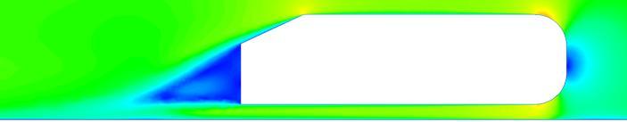
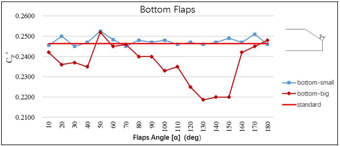
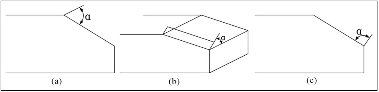
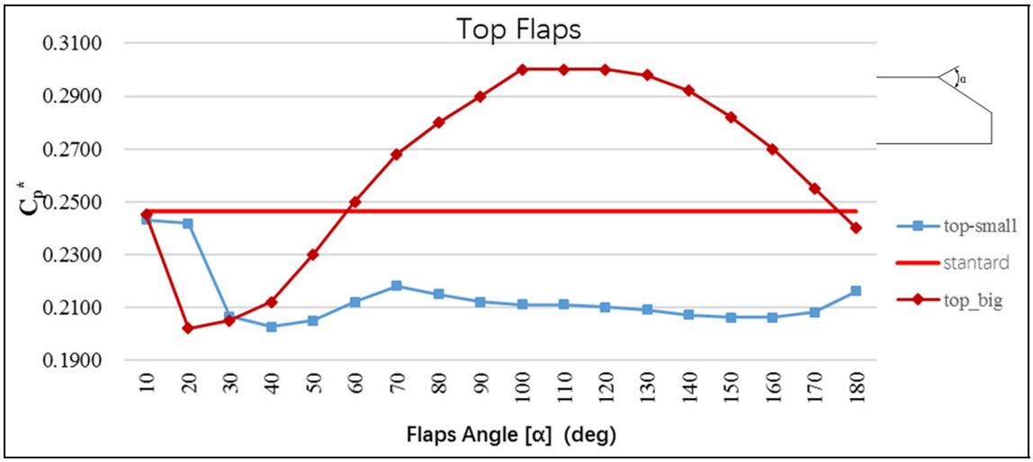
Tian et al. (2017) [9] numerically investigated the novel ADD ON device for two models of Ahmed body (i.e., with rear slant angles of 25° and 35°). Two types of flaps (i.e., “big type”and“small type”wereaddedonthetop,sideand bottomedgesofslantsurfaces(seefig 5)ofboththemodels of Ahmed body for analysis of aerodynamic drag. Simulations were carried out on STAR CCM+, the CFD softwareviaRANSbasedSSTk omegaturbulencemodelata Reynolds number of 4.29 million. Drag reduction was prominent for Ahmed body with 25°, whose results are showninfig 6.Variouscasesweremadefortheanalysisof theflapforAhmedbodywithφ=25°(i.e.,“Top_small_40, Top_big_20, Side_big_80, and Bottom_big_130” etc.) at different flap angles (α) in which Side_big_80 shows the highestdragreductionof21%.Furthermore,Ahmedbody witharearslantangleof35°showsadragof6%only.
International Research Journal of Engineering and Technology (IRJET)
Volume: 09 Issue: 04 | Apr 2022 www.irjet.net
Fig 5:LocationofFlaps(a)Top,(b)Side,and(c)Bottom
e ISSN: 2395 0056
p ISSN: 2395 0072
(a)Topflapsdragresults
(b)Sideflapsdragresults
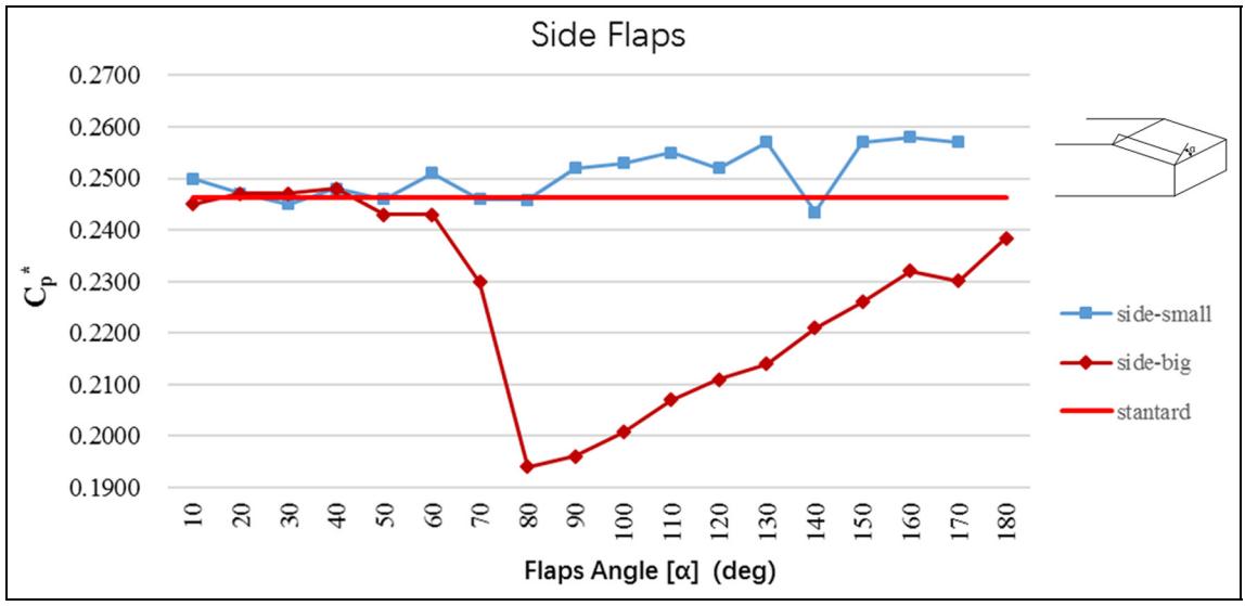
Bottomflapsdragresults
Fig 6:CFDdraggenerationfindingsforallthreeflapswithvaryingflapanglesforAhmedbodywithφ=25° Credit Tianetal.[9],SAGEPublicationsLtd.,(CreativeCommons Attribution4.0International CCBY4.0), https://doi.org/10.1177/1687814017711390
© 2022, IRJET | Impact Factor value: 7.529 | ISO 9001:2008 Certified Journal | Page3935
International Research Journal of Engineering and Technology (IRJET)
Volume: 09 Issue: 04 | Apr 2022 www.irjet.net
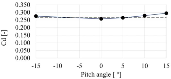
Cheng and Mansor (2017) [10] numerically analyzed the simplified hatchback car model (i.e., Ahmed body with φ=35°),tolookattheeffectofthepitchangleoftherear roofspoilerat 15°,0°,5°,10°,and15°.Thespoilerwas66.6 mminlength.Modelandspoilerconfigurationsareshownin fig 7(a)&(b).CFDsoftwareANSYSFLUENT16wasused forallaerodynamicsimulationsviaa “k epsilonrealizable model with enhanced wall treatment” Figure 7(c) shows thatdependingonthepitchangleoftherear roofspoiler,it mayhaveafavorableorunfavorableinfluenceonCd.Ithasa positiveimpactat0°and5°pitchangles.
e ISSN: 2395 0056
p ISSN: 2395 0072
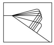
(b)Spoilerconfigurations.
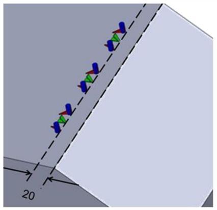
(a)ThethreevortexgeneratorsattachedtotheAhmed bodyarearrangedinastackedperspective.
(c)Dragcoefficientvs.rear roofspoilerpitchanglegraph; dashed horizontallineindicatesnospoiler.
Fig 7:Rearroofspoilerdesignandresults.
Credit ChengandMansor[10],IOPPublishingLtd, (CreativeCommons Attribution3.0Unported CCBY 3.0), https://doi.org/10.1088/1742 6596/822/1/012008
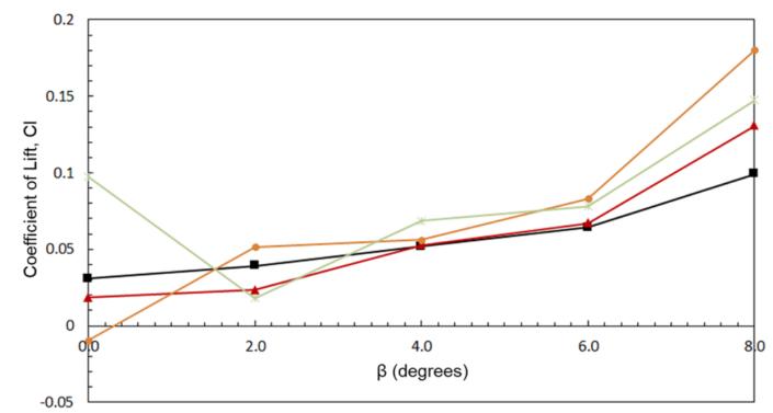
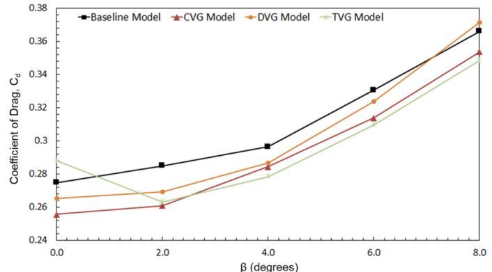
Viswanathan (2021) [11] used the CFD software ANSYS FLUENTversion19.1viaRANS basedmodels(i.e.,Realizable k ε,RNGk ε,SST k ω)toanalyzetheaerodynamicbehavior ofmultiplepassive(VGs)installedonaconventional
(b)DragresultsofdifferentVGsatvariousyawangles.
(c)LiftresultsofdifferentVGsatvariousyawangles.
Fig 8:VGsplacementandresults
Credit Viswanathan[11],SpringerNatureSwitzerland AG,(CreativeCommons Attribution4.0International CCBY4.0), https://doi.org/10.1007/s40430 021 02850 8
Ahmedbodywithφ=35°andsubjectedtovariousyawing angles (β). The numerical results are rigorously verified using previously reported experimental results for the Ahmed body. Different VGs are added (see fig. 8a) to the verified model (i.e., delta winglet, cylindrical, and trapezoidal).Allsimulationswereanalyzedforβ=0°to8° with an increment of 2°. The inclusion of CVGs and DVGs
© 2022, IRJET | Impact Factor value: 7.529 | ISO 9001:2008 Certified Journal | Page3936
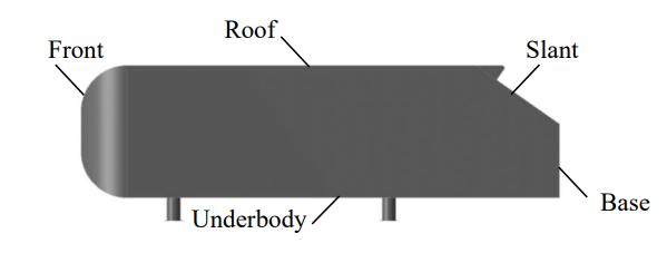 (a)Asimplifiedhatchbackwithaspoiler
International Research Journal of Engineering and Technology (IRJET)
Volume: 09 Issue: 04 | Apr 2022 www.irjet.net
proves the aerodynamic performance for (β=0°). On the other hand, the TVGs degrade performance by causing significant flow separation over the slant for (β=0°). In smaller vehicle yawing situations, the proposed CVGs and TVGslooktobecapableofreducingdragbyupto8.5%and 7.7%,respectively.Dragandliftresultsof differentVGsat variousyawanglesareshowninfig.8(b)&(c),respectively.
Thispaperreviewedtheaerodynamicdragreductionandits characteristics of an Ahmed body which is a simplified generic vehicle model for rear slant angles (φ) of 0° (a square back), 25° and 35° (a hatchback) using the CFD approach.DifferenttypesofADD ONsusedintheprevious studies are reviewed, such as porous layers, dimple grids based on the golf ball, V shaped Riblets, VGs of hemisphericalroundroughnesselements,flapsofdifferent sizes,rear roofspoilersandVGsofcylindrical,trapezoidal and delta shapes. The best ADD ON for the square back configurationofAhmedbodywasthedimplegridwiththe drag reduction of 36.5%, whereas for hatchback configuration(φ=25°)withsidebigflapsofangle80°was the best with the drag reduction of 21%. For hatchback configuration(φ=35°),thebestADD ONwerecombination of VGs attached on slant surfaces and V shaped Riblets attachedonrearsurfaceswithadragreductionof8.62%.All the study was numerically analyzed; none of them has experimentally analyzed the results. To compare flows, Particleimagevelocimetry(PIV)andCFDapproachesshould be deeply linked together. RANS simulations should be comparedtoPIVtechniques[12].
Modern artificial neural networks [13, 14] techniques can also be used to analyze the aerodynamic characteristics with better accuracy alongwiththeCFD.
[1] Muhammad Nabil Farhan Kamal, Izuan Amin Ishak, NofrizalidrisDarlis,DanielSyafiqBaharolMaji,Safra Liyana Sukiman, Razlin Abd Rashid, Muhamad Asri Azizul, A Review of Aerodynamics Influence on Various Car Model Geometry through CFD Techniques,” J. Adv.Res.FluidMech.Therm.Sci.,vol.88, no.1,Oct.2021,pp.109 125.
[2] W. M. Hamiga and W. B. Ciesielka, “Aeroacoustic Numerical Analysis of the Vehicle Model”, Appl. Sci., vol.10,no.24,Jan.2020.
[3] S.R. Ahmed, G. Ramm, and G. Faltin, “Some Salient Features Of The Time Averaged Ground Vehicle Wake,” in the SAE international congress and exposition (SAETechnicalPaper,1984),840300.
Factor value:
e ISSN: 2395 0056
p ISSN: 2395 0072
[4] V.NaveenKumar,K.LalitNarayan,L.N.V.Narasimha Raoand Y. Sri Ram, “Investigation of Drag and Lift ForcesovertheProfileofCarwithRearspoilerusing CFD,” Int. J. Adv. Sci. Res.,vol.1,no.8,Oct.2015.
[5] AlfadhelB.Kasim,Dr.SalahR.AlZaidee,“Validationof Computational Fluid Dynamics Technique for Turbulent Wind Flow Approach, Bluff Two Dimensional Body,” Int. J. Sci. Res., vol. 6, no. 4,April 2017,pp.1361 1369.
[6] Charles Henri Bruneau, Patrick Gilli´eron and Iraj Mortazavi, “Passive Control Around the Two DimensionalSquareBackAhmedBodyUsingPorous Devices,” J. Fluids Eng.,vol.130,no.6,May2008.
[7] Mohd Faruq Abdul Latif, Muhammad Nur Othman, QamarFairuzZahmani,NajiyahSafwaKhashi'ie,Beh Eik Zhen, Mohd Farid Ismail, Ahmad YusufIsmail, “Optimization of Boundary Layer Separation ReductionInducedbyTheAdditionofaDimpleGrid onTopofaBluffBody”,J.Adv.Res.FluidMech.Therm. Sci.,vol.64,no.2, Dec.2020,pp.173 182.
[8] X.Yang,Y.Hu,Z.Gong,J.Jian,andZ.Liu,“Numerical Study of Combined Drag Reduction Bases on Vortex Generators and Riblets for the Ahmed Body using IDDESMethodology”,J.Appl.FluidMech.,vol.15,no.1, Jan.2022,pp.193 207.
[9] J. Tian, Y. Zhang, H. Zhu, and H. Xiao, “Aerodynamic dragreductionandflowcontrolofAhmedbodywith flaps”, Adv. Mech. Eng., vol. 9, no. 7, Jul. 2017, 1687814017711390.
[10] S Y Cheng and S Mansor 2017 J. Phys.: Conf. Ser. 822 012008
[11] H. Viswanathan, “Aerodynamic performance of severalpassivevortexgeneratorconfigurationsonan Ahmed body subjected to yaw angles”, J. Braz. Soc. Mech.Sci.Eng.,vol.43,no.3,Feb.2021,p.131
[12] F.Szodrai,“QuantitativeAnalysisofDragReduction MethodsforBluntShapedAutomobiles”,Appl.Sci.,vol. 10,no.12,Art.no.12,Jan.2020,4313
[13] DYuStreletsetal2021IOPConf.Ser.:Mater.Sci. Eng. 1024 012115
[14] Juliette Marrie, Pierre Baqu´e, Wouter Remmerie, Francesco Bardi, Pascal Fua, “Multi fidelity optimization of a fixed wing drone using Geometric Convolutional Neural Networks,” January 29, 2020. https://airshaper.com/research/deep learning automated drone design