Volume: 09 Issue: 02 |
2022 www.irjet.net

e ISSN: 2395 0056
p-ISSN: 239-50072
Volume: 09 Issue: 02 |
2022 www.irjet.net
e ISSN: 2395 0056
p-ISSN: 239-50072
1M Tech Scholar, Department of EE, Dr.Babasaheb Ambedkar Technological University, Lonere, India
2Head Of Department, Department of EE, Dr.Babasaheb Ambedkar Technological University, Lonere, India
3Assistant Professor, Department of EE, Dr.Babasaheb Ambedkar Technological University, Lonere, India
4Assistant Professor, Department of EE, Dr.Babasaheb Ambedkar Technological University, Lonere, India
***
Abstract – This paper present gets maximum power from the solar PV system. In this paper, we have used the technique of Fuzzy Logic Controller based MPPT used for a 1 8KW solar PV system. The DC DC boost converter is used to generate high voltage. The solar PV system is designed and simulated using MATLAB/Simulink.
Key Words: Solar PV module, DC DC Boost Converter, FuzzyLogicControllerbasedMPPT
Power Enhancement day by day in this world. Renewable energy sources like solar energy, wind energy, and tidal energyarebeingused.Italsogivesaquickintroductionto the various techniques used by different countries to get overtheenergysituationaswellasaframeworkforusing such techniques in countries that are lagging in energy production in getting to obtain the benefits of energy sources, which are bountiful in the world [1]. The power quality of the grid linked RESs can be enhanced by utilizing different MPPT formulas. The fuzzy logic controllermaximumpowerpointtrackingutilizesaDC DC boost converter for controlling the solar input voltage to theoptimal power. Differenttechniques ofoptimal power monitoring in solar PV power applications have been reportedinliteraryworks[2].TheMPPTformulaplaysan essential contributionin producingoptimal power.Inthis researchstudywork,theFLC basedcontrollerisdesigned in a MATLAB atmosphere for the solar PV system. Ultimately,thesimulationoutcomesof thecontrollerhelp toobservetheoutputofthesysteminthedifferentloading conditions [3], [4]. The authors concluded that the recommended method has gotten over the conventional methods.
The solar PV module is light energy converted into electrical energy. Many typesofsolar PV modulessuch as Monocrystalline, Polycrystalline, and thin film PV modules.
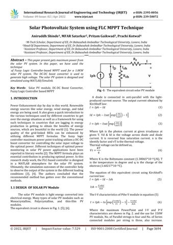
TheequivalentcircuitisshowninFig.1.[5],[6].
A diode is connected in anti parallel with the light produced current source. The output current obtained by Kirchhofflaw:
( )
* ( ) + ( )
( )+ ( )
Where Iph is the photon current at given irradiance at given T. Vd & Id is the voltage across diode and diode current. It is reversed bias saturation current. n is the identifyfactorandvTisthethermalvoltage. Thermalvoltagecanbedefinedas,
)
Where K is the Boltzmann constant (1.38065*10 23J/K), T is the temperature in degree and q is the charge of the electron(1.60217*10 19C).
The equation of this equivalent circuit using Kirchhoff’s currentlaw:
( )
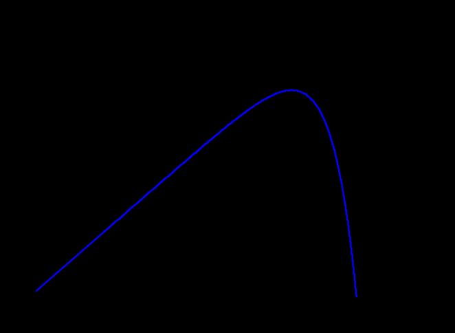
TheI VcharacteristicsofPtheVmoduleinequation(5)
( ) + ( )
Where the maximum PowerPoint and I V and P V characteristics are shown in Fig. 2. and the use for 150W PVmodule,No.ofParallelstringsisfourandNo.ofSeries connected modules per string is three, also increase.
International Research Journal of Engineering and Technology (IRJET) e ISSN: 2395 0056
Volume: 09 Issue: 02 | Apr 2022 www.irjet.net p-ISSN: 239-50072
Generated1.8KWpower. Table 1showstheparameterof the150WPVmoduleat250Cand1000w/m2 .
one voltage level into another voltage level by switching action.[6].
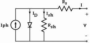
Theoperationoftheboostconverter,ontheotherhand, is to step up the input voltage and The boost converter circuit has IGBT or MOSFET switch are used. The boost converter operates in two modes When the switch is closed, the inductor stores energy, and the capacitor release energy. When switching open, the inductor releases energy, and the capacitor stores energy. The DC DCboostconverterisshowninFig.4 [6]
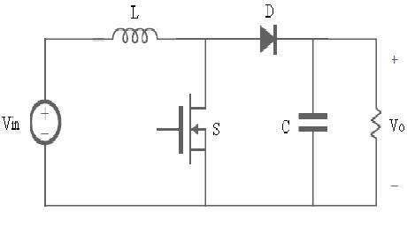
Fig 2:I VandP VcharacteristicsofSolarPVmodule
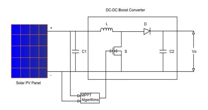
The circuit diagram of a solar PV system with a DC DC boost converter and MPPT is shown in Fig. 3. The disadvantage of the conventional MPPT algorithm is the poor efficiency of the weather condition is overcome the problemusingtheFLCMPPTalgorithm[6].
Fig 3:CircuitdiagramofsolarPVsystemwithaDC DC boostconverterandMPPT
Table 1: 150WPVmoduleat250Cand1000w/m2
1. Opencircuitvoltage(Voc) 41.8V Shortcircuitcurrent(IISC 5.05A
2. Thevoltageatmaximumpower poiVmpVmpp)
3. Currentatmaximumpowerpoint (Impp)
4. Maximumoutputpower
5. Cellspermodule 72
6. No.ofParallelstrings 4
7. No.ofSeriesconnectedmodules perstring(Ns) 3
The dc/dc boost converter we deal with here's a switching converter. Particularly, the dc dc boost converter is a power electronic devices circuit, which utilizes an inductor, a transformer, or a capacitor as an energy storage element to transform electric power from
The boost converter parameter values are calculated by the following formulae and Table 2 shows the parameter valuesoftheboostconverter:
Table 2: ParametervaluesofBoostConverter
1. Inputvoltage 125V
2 Outputvoltage 400v 500V
3 Switchingfrequency 25kHz
4 Inductance 7mH
5. Inputcapacitance 1000µF
6. Outputcapacitance 135µF
7 Resistance 30Ω
Monitoring the optimal power point of a photovoltaic arrayisanimportantphaseofasolarPVsystem.Thehuge varietyoftechniquessuggestedcanmakeitchallengingto identify the very best method to take on when applying a solarPVsystem.Themethodsalldifferinintricacy,variety of sensing units needed, electronic or analog application,
© 2022, IRJET | Impact Factor value: 7.529 | ISO 9001:2008 Certified Journal | Page3695
Volume: 09 Issue: 02 | Apr 2022
convergence rate, monitoring capability, and set you back efficiency.
The various techniques are used in MPPT for solar PV systems such as Constant Voltage (CV), Temperature (T), Open Voltage (OV), Feedback voltage (Current), Perturbation and Observation (P&O), Incremental Conductance (IC), Fuzzy logic controller (FLC), and ArtificialNeuralNetwork[7].
The Fuzzy logic controller has large series of applications in renewable resource applications. Using fuzzy logic controllers was enhanced over the last years duetoitssimpleness,managingimpreciseinputs,doesnot require a precise mathematical design, and can deal with nonlinearity. FLC can be utilized as a controller toacquire theoptimalpowerthatthesolarPVmodule[8].
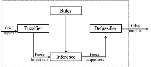
The procedure of a Fuzzy logic controller can be categorizedintothreephases,fuzzification,ruleevaluation, anddefuzzification.Theseelementsandthebasicstyleofa FLCSareshowninFig.5.
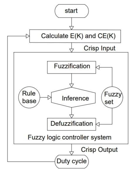
Thefivestepstosolvethemathematicalofafuzzylogic system. Step one is to identify input and output variables and decidedescriptors for the same. Thesecondstepis to define the membership function for each of the input and output variables as shown in Fig.7. The third and fourth step isfrom rulebase, ruleevaluation. Thelaststepinthe fuzzylogicsystemisdefuzzification[9] TheoutputofFLC isachangeinthedutycycleoftheDC DCboostcontroller. The procedure of defuzzification transforms the linguistic value of output into a crisp output value. The many methods of defuzzification such as lambda cut, maxima, weighted average, and the most commonly used centroid method.
In the recommended system, the input variables of the FLC are error (E) and the transform in error (CE) the output of FLC is transformed in the duty cycle. Develop factorstoconsiderandtheeffectivenessofthefuzzyMPPT formula depend upon the chosen input and the output variable picked. The output variable of the FLC MPPT formula is typically duty ratio regulated for changing the running factor of the PV Module to optimize the power output. One of the most generally utilized input variables for FLC MPPT is the incline of the P V curve of the PV
e ISSN: 2395 0056
p-ISSN: 239-50072
module and modifications in this slope. Since slope vanishes at the MPP, both inputs can be determined as complyingwith:
( ) ( ) ( ) ( ) ( ) ( ) ( ) ( ) ( )
WherePpvandVpvrepresentthepowerandvoltagein theP Vcurve.ErrorE(k)andCEbecomethecrispinputsof the fuzzy logic system. k and k 1 are the instants respectively. Theflowchartoffuzzylogic controllerMPPT isshowninFig.6.
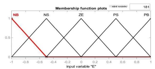
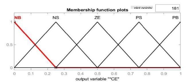
The various types of membership functions such as triangular,trapezoidal,andGaussianspecifiedmembership functions.Thetriangulartypemembershipfunctionisused becauseithaslesscomplexitywhensplittingvaluesofthe low, medium, and high MF. contrasting various other membershipfunctions.
These variables are revealed in various fuzzy sets: NB (negative big), NS (negative small), ZE (zero), PS (positive small), PB (positive big) as shown in the table 3 and Membershipfunctiontwoinputandoneoutputvariableis showninFig.7.
International
of Engineering and Technology (IRJET) e ISSN: 2395 0056
Volume: 09 Issue: 02 | Apr 2022 www.irjet.net
(b): Inputvariable“CE”
p-ISSN: 239-50072
Fig-12: Inductiveload:FLCMPPTOutputpower
(c): Outputvariable“*CE”
Fig 7: Membershipfunctiontwoinputandoneoutput variable
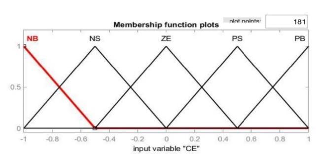
Table 3: FuzzylogicRule based CE*(o/p) CE(i/p)
NB NS ZE PS PB
NB ZE PB PB PB PB
E(i/p) NS PB PS PS ZE ZE
ZE PS ZE ZE ZE NS
PS ZE ZE NS NS NB
PB PB ZE NS NB ZE
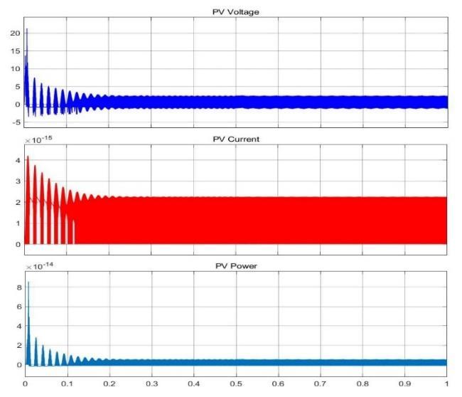
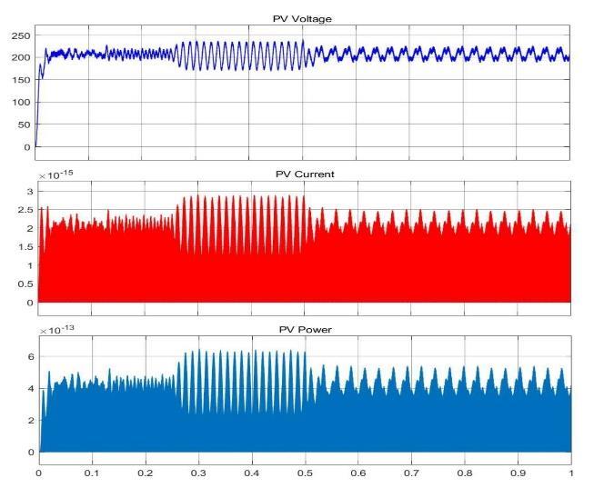
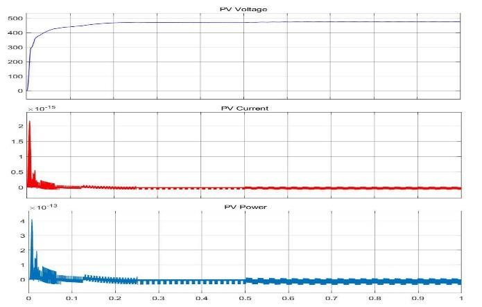
Fig 13: Capacitiveload:FLCMPPTOutputpower
Fig-11: Resistiveload:FLCMPPTOutputpower
© 2022, IRJET | Impact Factor value: 7.529 | ISO 9001:2008
International
of Engineering and Technology (IRJET) e ISSN: 2395 0056
Volume: 09 Issue: 02 | Apr 2022 www.irjet.net p-ISSN: 239-50072
Fig 15: Resistive Capacitiveload:FLCMPPTOutput power
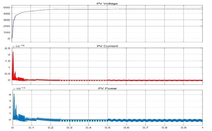
Fig 18: Opencircuit:FLCMPPTOutputpower
Table 4: ResultsofSPVSysteminFLC basedMPPT
SR.NO Load FLC MPPT Output power
Voltage (V) Current (A) Power (W)
1. R 203V 2.122A 430.7W
2. L 0.7566V 2.245A 1.698W
3. C 474.9V 5.302A 2517.9W
4. RL 203.1V 2.122A 430.97W
5. RC 474.9V 3.841A 1824.09W
6. LC 474.9V 9.721A 4616.5W
7. RLC 474.9V 9.502A 4512.4W
8. Open circuit 474.8V 9.274A 4395.8W
Fig-16: Inductive Capacitiveload:FLCMPPTOutput power
This paper proposed a technique to generate power using the solar photovoltaic system with a fuzzy logic controller based maximum power point tracking method at different loading conditions. The active power is generated during the Resistive and Inductive, Resistive Inductive loading conditions. The reactive power is obtained from Capacitive, Resistive Capacitive, Inductive Capacitive, Resistive Inductive Capacitive load, and Open circuitloadingconditions
[1] R. M. Elavarasan, ‘‘The motivation for renewable energyanditscomparisonwithotherenergysources: Areview,’’Eur.J.Sustain.Develop.Res.,vol.3,no.1,p. em0076,Feb.2019.
Fig 17: Resistive Inductive Capacitiveload:FLCMPPT Outputpower
[2] Fernando Lessa Tofoli, Dênis de Castro Pereira, and Wesley Josias de Paula, “Comparative Study of Maximum Power Point Tracking Techniques for Photovoltaic System” International Journal of PhotoenergyVolume2015
[3] T. U. Hassan, R. Abbassi, H. Jerbi, K. Mehmood, M. F. Tahir, K. M. Cheema, R. M. Elavarasan, F. Ali, and I. A. Khan, ‘‘A novel algorithm for MPPT of an isolated PV system using a push pull converter with fuzzy logic
© 2022, IRJET | Impact Factor value: 7.529 | ISO 9001:2008 Certified
International
Journal of Engineering and Technology (IRJET) e ISSN: 2395 0056
Volume: 09 Issue: 02 | Apr 2022 www.irjet.net p-ISSN: 239-50072
controller,’’ Energies, vol. 13, no. 15, p. 4007, Aug. 2020.
[4] M. Rajvikram, P. Renuga, and M. Swathisriranjani, ‘‘Fuzzy based MPPT controller’s role in the extraction of maximum power in wind energy conversion system,’’inProc.Int.Conf.Control,Instrum.,Commun. Comput.Technol.(ICCICCT),Dec.2016,pp.713 719.
[5] H. Bellia, R. Youcef, and M. Fatima, ‘‘A detailed modeling of photovoltaic module using MATLAB,’’ NRIAG J. Astron. Geophysics, vol. 3, no. 1, pp. 53 61, Jun.2014.
[6] P. Verma, R. Garg, and P. Mahajan, “Asymmetrical interval type 2fuzzy logiccontrol basedMPPTtuning for PV system under partial shading condition” ISA Transactions(2020),
[7] Saleh Elkelani Babaa, Matthew Armstrong, Volker Pickert,“OverviewofMaximumPowerPointTracking Control Methods for PV Systems” Journal of Power andEnergyEngineering,2014
[8] Abdullah M. Noman, Khaled E. Addoweesh, and Hussein M. Mashable, “A Fuzzy Logic Control Method forMPPTofPVSystems”2012IEEE.
[9] AnweshaPanigrahiandKanhuCharanBhuyan,“Fuzzy Logic Based Maximum Power Point Tracking AlgorithmforPhotovoltaicPowerGenerationSystem” JournalofGreenEngineering,Vol.64,403 426.
value: