International Research Journal of Engineering and Technology (IRJET)

Volume: 09 Issue: 04 | Apr 2022 www.irjet.net
e ISSN: 2395 0056
p ISSN: 2395 0072
International Research Journal of Engineering and Technology (IRJET)
Volume: 09 Issue: 04 | Apr 2022 www.irjet.net
e ISSN: 2395 0056
p ISSN: 2395 0072
1M.Tech, Civil Engineering, Suyash Institute of Information Technology, Gorakhpur, Uttar Pradesh
2Assistant Professor, Civil Engineering, Suyash Institute of Information Technology, Gorakhpur, Uttar Pradesh
***
Abstract - In this research study is a comparative study on the different shapes of the RC building (horizontal irregularities building) by using the viscous or fluid viscous damper. There are three models in this research paper which first, the second, and the third model is H, T, and L shape respectively. These models are analyzed with the help of the ETABS software and by using IS Code 1893 part 1 2016. Inthis research paper, we took some seismic parameters for comparison among the models such as base shear (lateral forces at the storey due to seismic), natural period, storey stiffness, storey drift, storey overturning moment, and storey displacement. The material and geometrical properties of all models are the same such as the dimension of the beam, column, and slab. We considered the seismic zone inthe fourth zone. All models are analyzed by the dynamic analysis with the help of the time history method and data of the time history is taken from “EL CENTRO” this data represents the graph ofthe acceleration vs. time of the earthquake e in Mexico
manageshockvibration,seismicvibrationmaybecontrolled by using fluid viscous dampers. Viscous damper mathematicalmodellinganddynamicanalysis. Themaintenanceandapplicationofanystructurearethus jeopardisedasthepopulationgrows.Aquake safestructure, according to conventional norms, can withstand the most severe shaking that might occur in that specific zone. Regardless, the most effective technique for designing a shakingsecurestructureistorestrictthepassingaswellas the decimation of the fundamental component's functionality.Fromhistoricalandrecentrecords,theworld hasseenseveraldevastatingseismicearthquakes,increasing thenumberofpeoplekilledasaresultofbasiccrumplesand severestructuraldamage.
Energydissipationdevicesarethemostcommoncomponent ofstructuralpassivecontrolsystems.Dampingisaneffect thatoccursinsideoronanoscillatorysystemthatreduces, limits,ormaintainsitsoscillations.Dampingisestablishedin physical frameworks by techniques that separate the intensity stored in the oscillation. In the simplest terms, a seismic earthquakeisdefinedasshakingandvibrationon thesurfaceoftheearthcausedbysubsurfacegrowthalonga flat plane. Tremors are caused by seismic waves, which inducevibrations.Seismicwavesarethemosttragic.[1]The recentadvancementintheuseofpassiveenergyabsorption technologies for structural earthquake resistance. In a shaking table, multi story scale model building structures areevaluatedandsubjected toa semi activefluiddamper control system. [3] The seismic effect of an 8 story RC building seismic energy dissipation device application in China is viscous damper, visco elastic damper, and steel damper. [4] High capacity friction dampers based on the rotatingfrictionprincipleareinstalledintallconstructions. [5]Frictionaldampersinsingle storyconstructionsprevent seismicaction.[6]Theseismicresponseofaviscousdamper is calculated using complicated damper theory. [7] To
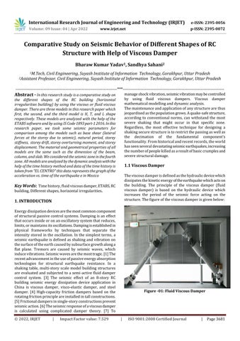
Theviscousdamperisdefinedasthehydraulicdevicewhich dissipatesthekineticenergyoftheearthquakewhichactson the building. The principle of the viscous damper (fluid viscous damper) is based on the hydraulic device which increases the period of the seismic force acting on the structure.Thefigureoftheviscousdamperisgivenbelow:
International Research Journal of Engineering and Technology (IRJET)
Volume: 09 Issue: 04 | Apr 2022 www.irjet.net
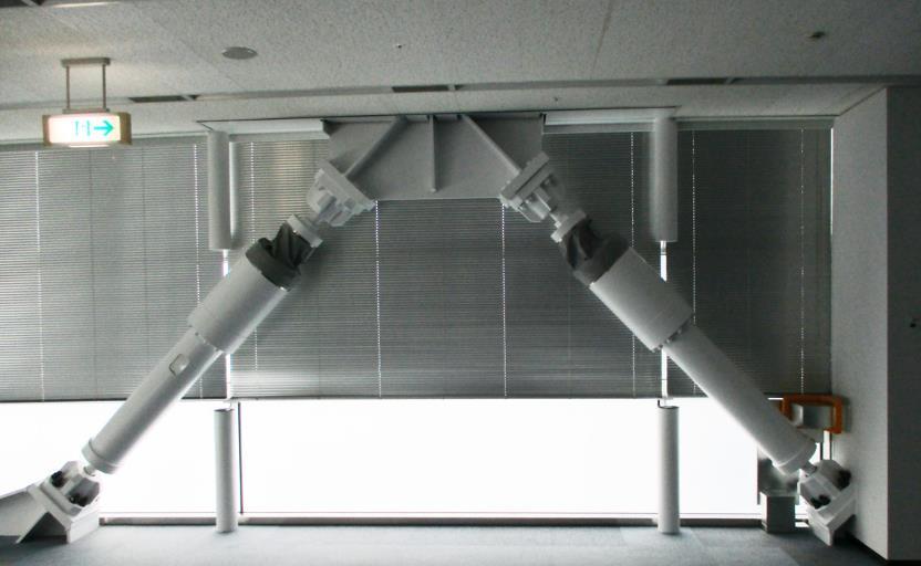
In the following figure, the parameter of the fluid viscous damperisgivenbelowandwetakethefluidviscousdamper whoseforceis500KNandmassis98Kginthemodel:
AccordingtotheISCode1893part 12016,fromclause7.1, irregularconfigurationisgivenindifferentconditionssuch as “Torsional irregularities, and re entrant corner. All modelsinthispaperarecomesunderthehorizontal(plan) irregularities, where the re entrant corner is present in everymodel.
In this paper, we used the time history method for the analysisofallmodelsbyusingtheEtabssoftware,alsothe verticalloadcombinationaccordingtotheIScode1893part 1:2016fromclausenumber6.3.4.1.
ThismethodisalsoknownastheTimehistorymethod,and this method is used when the variation of the forces concerning the time was high .and in this method we provided the data of time history “EL CENTRO”, The 1940“EL CENTRO” earthquakeSouthernCalifornianearthe internationalborderoftheUnitedStatesandMexicoandthe magnitudewas6.9.
Theviscousdamperwhichisusedinthismodeltodecrease thestoreydisplacementandsomeotherseismicparameter whichactonthestructureisgivenbelowintheformofthe table:
Impact Factor value: 7.529
e ISSN: 2395 0056
p ISSN: 2395 0072
Table 1: ParameterofFVD
Force (KN) Taylor Device model number
Weight (Kg) 500 17120 114 44
Maximum cylinder Diameter (mm)
Inthemodeldetails,wewillgiveanddiscusstheparameter ofthebuilding,seismicparameters,andloadandmaterial parameters.
In this parameter, we give the details about the material whichisusedinthebuildingandthematerialparameteris givenbelowinthetable:
Table 2: MaterialParameter
S. No Material Grade
01. Concrete M30
02. HYSDSteel Fe415
03. MildSteel Fe250
In this parameter, we give the details about building parameters such as the size of beam, column and slab is givenbelowinthetable:
Table 3: BuildingParameter
S.No Building Parameter Value
01. Beam 300mm 450mm 02. Column 350mm500mm 03. Slab 150mm 04. SpanofBeam 3.5m 05. Heightofbuilding 48.5m 06. Floorheight 3m 07. Groundstorey 3.5m
International Research Journal of Engineering and Technology (IRJET)
Volume: 09 Issue: 04 | Apr 2022 www.irjet.net
Inthisparameter,wearegiventheparameteroftheseismic where the model is assumed to construct such as seismic zonefactor,Importancefactor,etc
Table 4: SeismicParameter
01. SeismicZoneFactor(Z) 0.24(Forth Zone)
02. ResponseReductionFactor (R)
03 Importancefactor(I) 1.2
04. Soiltype 2nd
05. Eccentricratio 5%
TheloadwhichisactingonthestructuresuchasImposed load,Seismicload,etcisgiveninthetable:
Table 5: LoadParameter
01. Liveload 3KN/m
Partitionwall
03. Loaddistributionwall
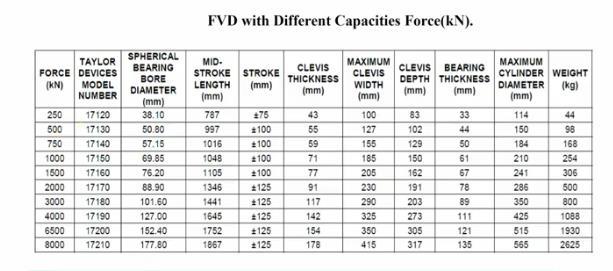
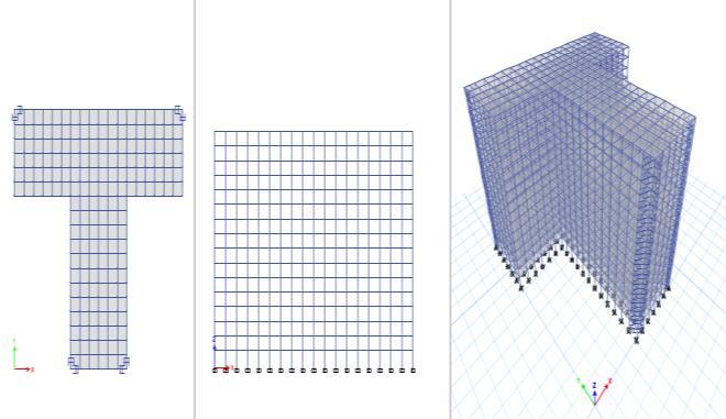
The plan, elevation and three dimensional view of the model 01aregivenbelow:
IRJET
e ISSN: 2395 0056
p ISSN: 2395 0072
Impact Factor value: 7.529
Figure 03:Plan,Elevationand3DviewofModel 01
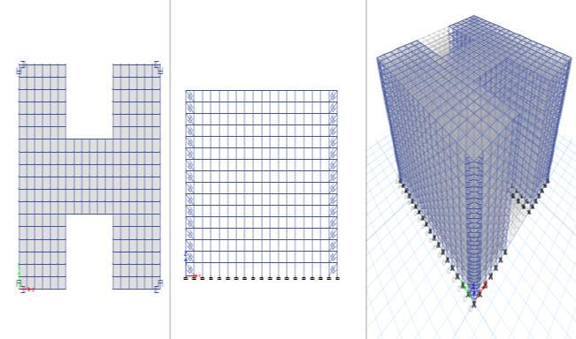
3.6 Plan, Elevation and 3D of Model 02
The plan, elevation and three dimensional view of the model 02aregivenbelow:
Figure 04:Plan,Elevationand3DviewofModel 02
3.7 Plan, Elevation and 3D of Model 03
Figure 05:Plan,Elevationand3DviewofModel 03
9001:2008
International Research Journal of Engineering and Technology (IRJET)
Volume: 09 Issue: 04 | Apr 2022 www.irjet.net
Inthischapter,weanalyzetheresultwhichcameafterthe analysisofthisentiremodel,wetakesomeparametersofthe seismic such as natural period, base shear, storey displacement, storey stiffness, storey drift, etc. based on these parameters we will check that which shape of the modelismorestableascomparedtoothertwomodels.
From clause 3.18 from Indian Standard Code 1893 part 1:2016, the natural period in the mode of oscillation is definedasthetime(inasec)takenbystructuretocomplete one rotation of the oscillation in its natural mode of wavering. Thefollowing graphrepresents the variation of thenaturalperiod:
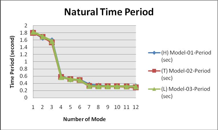
ConcerningtheIndian Standradradcode1893part 1:2016, thenaturalperiodofRCCstructureshouldexistin0.05to 2.00seconds
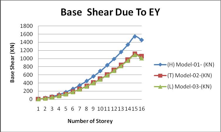
Fromclause7.2.1,fromIndianStandardcode1893part 1: 2016,thebaseshearisdefinedasthelateralforceswhichact ateverystoreyduetoseismiceffectonthestructure. The following graph represents the base shear (lateral forces) of all models in the X direction due to applying seismiceffectintheYdirection:
e ISSN: 2395 0056
p ISSN: 2395 0072
Fromtheabovegraph,wecanseethatthevalueofthebase shearismaximumintheHshapebuilding.
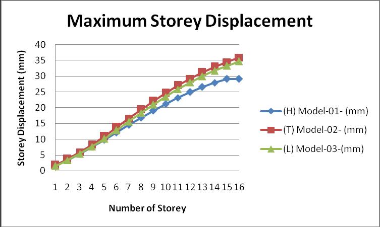
Itisdefinedasthedisplacementofeverystoreyconcerning the ground which is developed due to the effect of the seismicforcesonthestructure
The graph of the maximum storey displacement is given belowforallmodels:
International Research Journal of Engineering and Technology (IRJET)
Volume: 09 Issue: 04 | Apr 2022 www.irjet.net
From the above graph, we can see the value of maximum storeydisplacementintheTshapebuilding.
Storey Drift is defined as the relative displacement of the storeyconcerningthetoporbelowthestorey.Storeydrift doesnotcalculateconcerningthegroundsurface.
The graph of the storey drift of all models is given in the formofthegraph:
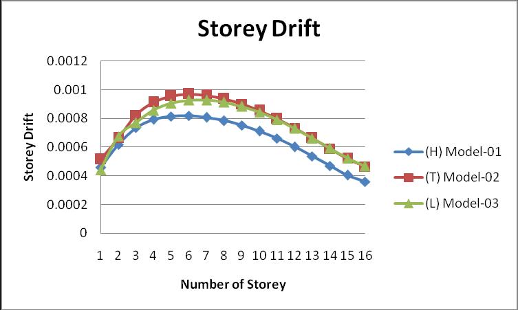
ConcerningtheIndianStandardcode,thebecauseofstorey driftshouldnotexceed0.004heightofthefloor.
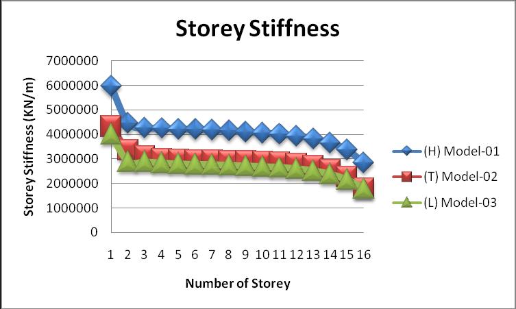
Storey stiffness is defined by Indian standard code 1893 part 1:2016,itistheratioofthestoreysheartothestorey drift.
Thegraphofthestoreystiffnessofallmodelsisgivenbelow:
Impact Factor value: 7.529
e ISSN: 2395 0056
p ISSN: 2395 0072
Fromtheabovegraph,wecanseethatthevalueofthestory stiffnessishighintheHshapebuilding.
Therearethreemodelsinthispaper(H,TandL)andthese models are linked with the fluid viscous damper, and analysisthere modelswefoundsomeconclusionwhich is givenbelow:
i. FromthegraphofthebaseshearduetoEY,wecan seethatthevalueofthebaseshearisminimumin the model 03 because the dead load is low in the model 03ascomparedtotheothertwomodels(H andT)andimposedloadisconstantinthesethree models.
ii. From the graph of the maximum storey displacement, we can see that the storey displacement of the model 01(H) is low as comparedtoanothertwomodels(TandL),because theHshapeissupportedfromeverywhere,andit can easily transfer the lateral load in the all direction,whereinanothertwomodelsitisdifficult totransfer.
iii. According to the Indian Standard Code, if an RCC Buildinghasflooroneto20thenthenaturalperiod should exist from 0.005 to 2.00second, with this referenceallmodelisinthesafe.Thevalueofthe naturaltimeofmodel 02is1.86%lessascompared tomodel 01and1.54%lessascomparedtomodel 02.
iv. Thevalueofthestoreystiffnessofthemodel 03(L) islowascomparedtothetwomodels.Thevalueof thestoreystiffnessofmodel 03is32.82%lessthan model 01 and 7.18% less than as compared to model 02.
[1] A.Ras andN.Boumechra“Seismic energydissipation studyoflinearfluidviscousdampersinsteelstructure design”Elsevier 2016.
[2] LauraGioiella“Analysisandcomparisonoftwodifferent configurations of external dissipative systems” ScienceDirect 2017.
[3] Giuseppe Marcantonio Del Gobbo “Improving total buildingseismicperformanceusinglinearfluidviscous dampers”https://doi.org/10.1007/s10518 018 0338 4,2018
[4] F.Hejazi,J.Noorzae “EarthquakeAnalysisofReinforce Concrete Framed Structures with Added Viscous Dampers” https://www.researchgate.net/publication/242782634, 2109.
[5] IS 456 2000 “Code practice for plain and reinforced concrete”.
[6] IS:875(Part2) 1987“CodeofPracticefordesignloads forbuildingsandstructures”
International Research Journal of Engineering and Technology (IRJET)
Volume: 09 Issue: 04 | Apr 2022 www.irjet.net
[7] Symans, Michael D, and Michael C. Constantinou, "Seismic testing of a building structure with a semi‐active fluid damper control system." Earthquake Engineering & Structural Dynamics, Vol. 26, Issue 7, 1997,pp.759 777.
[8] . Lu, X. L, K. Ding, D. G. Weng, K. Kasai, and A. Wada, "ComparativestudyonseismicbehaviourofRCframe structure using viscous dampers, steel dampers and viscoelasticdampers." In Proceedings of the 15th World Conference on Earthquake Engineering,2012.
[9] .Heysami,Alireza,"Typesofdampersandtheirseismic performance during an earthquake." Current world environment,Vol.10,2015,pp.1002 1015.
[10] ..Bhaskararao,A.V,andR.S.Jangid,"Seismicanalysisof structures connected with friction dampers." Engineering Structures,Vol.28,Issue5,2006,pp.690 703.
[11] .Mualla,I.H,L.O.Nielsen,M.Sugisawa,andY.Suzuki, "Large capacitydampersforbuildingsandstructures." In 15h World Conference on Earthquake Engineering, Lisbon, Portugal,2012.
[12] . Min, Kyung Won, Ji Young Seong, and Jinkoo Kim, "Simple design procedure of a friction damper for reducingseismicresponsesofasingle storystructure." Engineering Structures, Vol. 32,Issue11,2010,pp.3539 3547.
[13] . Cheng, Xuansheng, Chuansheng Jia, and Yue Zhang, "Seismic responses of an added story frame structure with viscous dampers." Mathematical Problems in Engineering (2014).
[14] .Narkhede,D.I.,andR.Sinha,"Shockvibrationcontrol ofstructuresusingfluidviscousdampers."In 15 WCEE (World Conference on Earthquake Engineering).2012
[15] . Xu, Zhao Dong, "Earthquake mitigation study on viscoelasticdampersforreinforcedconcretestructures." Journal of Vibration and Control,Vol.13,Issue1,2007, pp.29 43.
[16] . Samali, B., and K. C. S. Kwo, "Use of viscoelastic dampers in reducing wind and earthquake induced motionofbuildingstructures." Engineering Structures, Vol.17,Issue9,1995,pp.639 654.
[17] . .LI, Hongnan, Gang Li, Zhongjun Li, and Fuguo Xing, "Earthquake resistantdesignofthereinforcedconcrete framewithmetallicdampersofdualfunctions" Journal of Building Structures,Vol.4,2007,pp.005.
[18] . Midorikawa, Mitsumasa, and Tetsuhiro Asari, "Earthquakeresponseoften storystory drift controlled reinforced concrete frames with hysteretic dampers." Engineering Structures,Vol.32,Issue6,2010,pp.1735 1746.
[19] .IS1893(part1):2016criteria forearthquakeresistant designofthestructure.
e ISSN: 2395 0056
p ISSN: 2395 0072