International Research Journal of Engineering and Technology (IRJET)

e ISSN: 2395 0056
Volume: 09 Issue: 04 | Apr 2022 www.irjet.net p ISSN: 2395 0072
DESIGN THINKING ON FAULT DIAGNOSIS OF FLOATING WIND TURBINE GENERATOR USING ARTIFICIAL INTELLIGENCE
Dr.B.Sivasankari1 , G.Sathish Kumar2 , R.Prakash3 , S.Sanjanaa4 , N.Subhashree5
1Associate Professor, Dept of Electronics and Communication Eng, SNS College Of Technology Coimbatore, Tamil Nadu India.
4UG Student, Dept of Electronics and Communication Eng, SNS College Of Technology Coimbatore, Tamil Nadu India. ***
Abstract Floating wind turbines are the centerpiece of offshore floating power generation and an important means of developing offshore wind resources. In few years, artificial intelligence technology has achieved great results in many fields, and equipment fault diagnosis is also much important. Since the working environment of the floating fan is bad and far from the land, a failure of the floating fan generator can have very serious consequences. Based on the research results of AI technology, this article focuses on the application of AI technology in fault diagnosis of floating wind turbines and proposes a fault diagnosis intelligent system framework. According to the research of expert systems and artificial neural networks, the floating fan generator failure diagnosis technology is proposed, and the artificial neural network model and the reasonable failure receive the diagnostic reasoning flow.
1. INTRODUCTION
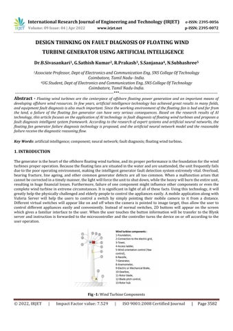
Thegeneratoristheheartoftheoffshorefloatingwindturbine,anditsproperperformanceisthefoundationforthewind turbinesproperoperation.Becausethefloatingfansaresituatedinthewaterandareunattended,theunitfrequentlyfails duetothepooroperatingenvironment,makingtheintelligentgeneratorfaultdetectionsystemextremelyvital.Overload, bearing fracture, line ageing, and other common generator defects are all too common. When a malfunction arises that cannotbecorrectedinatimelymanner,thelightwillforcetheunittoshutdown,whiletheheavywillburntheentireunit, resulting in huge financial losses. Furthermore, failure of one component might influence other components or even the completewindturbineinextremecircumstances.Itissignificantinlightofallofthese facts.Usingthistechnology,itwill greatlyhelpthephysicallychallengedandelderlypeopletocontroltheapplianceseasily.Amobileapplicationalongwith Vuforia Server will help the users to control a switch by simply pointing their mobile camera to it from a distance. Different virtual switches will appear like on and off when the camera is pointed to image target, thus allow the user to control different appliances easily and conveniently. Instead of normal switches, 2D buttons will appear on the screen which gives a familiar interface to the user. When the user touches the button information will be transfer to the Blynk server and instruction is forwarded to the microcontroller and the controller turns the device on or off according to the useroperation.
International Research Journal of Engineering and Technology (IRJET)
Volume: 09 Issue: 04 | Apr 2022 www.irjet.net
1.1ARTIFICIAL INTELLIGENCE TECHNOLOGY
e ISSN: 2395 0056
p ISSN: 2395 0072
Artificial intelligence technology is to study and make computers simulate normal human activities (such as learning, thinking, etc.). In the fault diagnosis of the floating wind turbine generator, by building the expert knowledge system database artificial intelligence technology can carry out fault diagnosis of the generator in advance. Through continuous learningofneuralnetworks,thedataoffaultsinexpertknowledgesystemscanberecorded,andthencontinuouslearning andevolutioncanbeachieved.Theartificialintelligencesystemcanimprovetheefficiencyandaccuracyoffaultdiagnosis ofwindturbinegenerators.
1.2 ARTIFICIAL NEURAL NETWORKS
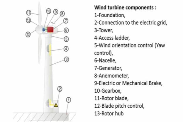
Artificial neural networks (NNs) are simplified simulations of the neurological systems of living organisms. A neural network (NN) is a data processing system made up of a large number of simple, densely interconnected processing components (artificial neurons) in a form inspired by the cerebral cortex's organization. The interconnected neural computingpartshavethepotentialtolearnandhenceaccumulateknowledge,allowingforeventpredictionareas .where NNscanbeusedinforecasting,patternrecognition,optimization,controlsystemsandimageprocessing
Fig 2: NeuralNetwork
2. LITERATURE SURVEY
Hue,Liu Xiu wen ,Bian Jing yu.[1].“TheApplicationofArtificial Intelligence Technologyin theFaultDiagnosis ofFloating WindTurbineGenerator”.
Qi Ping Yang, Meng Qun Li, Xue Yun Mu, Jun Wang.[2].”Application of Artificial Intelligence (AI) in Power Transformer FaultDiagnosis”.
YirongLiu,ZidongWu,XiaoliWang.[3].“ResearchonFaultDiagnosisofWindTurbineBasedonSCADAData”
Xiaojia Kong, Tongle Xu, Junqing Ji, Fanghao Zou, Wei Yuan,Leian Zhang. [4]. “Wind Turbine Bearing Incipient Fault DiagnosisBasedonAdaptiveExponentialWaveletThresholdFunctionWithImprovedCPSO”.
Hameed, Z,Hong, Y.S,Cho, Y.M,Ahn, S.H,Song, C.K. [5].”Condition monitoring and fault detection of wind turbines and relatedalgorithms”.
BillChunPiuLau,EdenWaiManMa,MichaelPecht.[6].”OffshoreWindTurbineFailuresandFaultPrognosticMethods”.
Par Marklund,Kim Berglund. [7].”Bearing monitoring in the wind turbine drive train a comparative study of the FFT and wavelettransforms”.
MNithya,S.Nagarajan,P.Navaseelan.[8].”Faultdetectionofwindturbinesystemsusingneuralnetworks”.
Acho,L.;Rodellar,J.;Tutivén,C.;Vidal,Y. [9].”PassiveFaultTolerantControlStrategyinControlledWindTurbines”
© 2022, IRJET | Impact Factor value: 7.529 | ISO 9001:2008 Certified Journal
Page3583
International Research Journal of Engineering and Technology (IRJET)
Volume: 09 Issue: 04 | Apr 2022 www.irjet.net
3. HARDWARE
e ISSN: 2395 0056
p ISSN: 2395 0072
The hardware components and materials that we used in the system are Battery, Power Supply, Temperature Sensor, VibrationSensor,SpeedSensor,PIC16F877
3.1 Battery
A battery is an implement that converts chemical energy into electrical energy Battery is composed of one or more electrochemicalcells,whicharecomposedoftwohalfcellsconnectedinseriesbytheconductiveelectrolyte. Voltaiccells areconnectedinserieswithoneormore
3.2 Power Supply
The power supply should be +5V no transistors exceeding 10mV. The voltage should be suitably tuned to get high / enoughcontrastforthedisplayinpin3.
Amodulemustnotbeinstalledorremovedinalivecircuit.Thepowersupplyofthegroundterminalmustbecongruously isolated so that no voltage is induced to it. The module must be isolated from the rest of the circuitry to prevent stray voltagesfromflickeringdisplay.

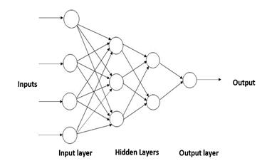
Fig 3: CircuitDiagram
3.3 Temperature Sensor
A temperature sensor is a utensil, customarily a resistance temperature detector or a thermocouple It uses an electrical signal to deliver temperature measurements in a legible form. A thermometer is the most cardinal type of temperature meter, and it is used to determine how balmy or cold. In the geotechnical profession, temperature meters are used to monitorconcrete,soil,structures,water,bridges,andstructuralchangescausedbyseasonalvariations.
3.4 Vibration Sensor
Vibration sensors detect vibration using piezoelectric accelerometers. They're used to quantify variable accelerations or speeds,aswellastypicalvibrations.Processcontrolsystems,aerialnavigation,andunderseaapplicationsareexamplesof applications where vibration sensors are used. The piezoelectric plate is a type of sensor used to detect mechanical vibrations.Themechanicalvibrationisconvertedtoanelectricalsignalbyapiezoelectricplate.Thetransformedelectrical signalhasavoltagerangeofafewmillvolts
International Research Journal of Engineering and Technology (IRJET)
Volume: 09 Issue: 04 | Apr 2022
3.5 Speed Sensor
e ISSN: 2395 0056
p ISSN: 2395 0072
Aspeedsensorisofteninstalledonthesideofawheelaxleortheaxleofatractionmotoranddrivenbyapinpushedinto theaxle.Whenthismountingmethodisused,thespeedsensorgear'scentrealmostalwaysdiffersfromtheaxle'scentre. Theinfluenceoftheeccentricityofthespeedsensorgearhasbeeninvestigated.
3.6 PIC 16F877
Microchip's PIC 16F877 is one of their latest microcontrollers. Due to its economical price, wide variety of applications, goodqualityandeasyavailability,thiscontrolleriswidelyusedforexperimentalandcurrentapplications.Itissuitable for a variety of applications including machine control, measuring devices, research, etc. The PIC 16F877 has all the componentsfoundincurrentmicrocontrollers.
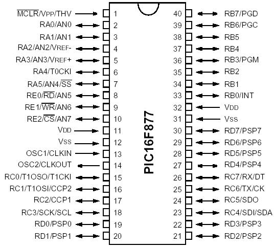
PINDiagramof16F877
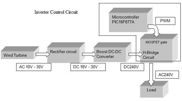
4. EXISTING SYSTEM
Wind turbines are programmed to deliver consistent active and reactive power for a set length of time in order to contributetothe powergrid. We compare the performanceofthree formsof separateactive and reactive power control forhorizontal axiswindturbinesinthis paper:thedirectmethod witha (PI)anda Fuzzy Logiccontroller,as well asthe indirectmethodcontrolwithpowerfeedback.
International
Volume: 09 Issue: 04
Technology (IRJET)
e ISSN: 2395 0056
p ISSN: 2395 0072
4.1 BOOSTER CONVERTER
A boostconvertercanonlyincreasethevalueoftheoutputvoltagetothepointwheretheoutputvoltageisgreaterthan theinputvoltage.Theboostconvertercircuitswillstep upthelowDCvoltagetoahighDCvoltage.Thebasiccircuitsofa boostconverterusepowerMOSFETs.WhenthepowersupplyisON,thecircuitoperatesandthecurrentflowsbywayof theinductor,L,anditwillstoretheenergy.Thestoredenergyintheinductorwillbetakenouttoloadif thepowersupply isturnedOFF.
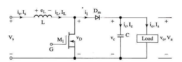
Fig 7: BoosterConverterCircuit
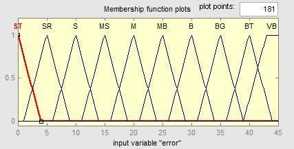
4.2 BASIC OF FUZZY LOGIC CONTROLLER
The fuzzy logic system is simple to learn, develop, and use, and it outperforms other types of controllers. By performing basic rules guiding the system's behavior, a fuzzy logic controller is developed into an automatic way of modifying the language of control steps. By mixing multiple ways of thinking at a higher level of abstraction, fuzzy logic permits the modeling of complex systems based on knowledge and experience. For the control algorithm that affects the system variables and a rule table, fuzzy logic variables are described. The gain is calculated by dividing the input voltage by the averageoutputvoltagevalue.
4.3 METHODHOLOGY
Themethodologyforthisprojectfollowsthesesteps:
Developanddesigntheboostconvertercircuit
Basedontheliterature.
DesignandenlargetheFuzzyRulesfortheFuzzy
LogicControllerbasedfromthegainresponse
International Research Journal of Engineering and Technology (IRJET)
Volume: 09 Issue: 04 | Apr 2022 www.irjet.net
Graph.
Restoringtheboostconverterwith/withouttheFLC
Integratedfortransientresponsebasedfrom
Differentinputvoltagelevels.
e ISSN: 2395 0056
p ISSN: 2395 0072
4.4 Disadvantages
ItdescribesthedesignanddevelopmentofafuzzylogiccontrollerboostDC DCconverterforrenewableenergy.Basedon comparisonsimulationresults,usingtheMATLABSIMULINKisthemostconvenientwaytodesignthecircuit.Thisproject is responsible with the design and simulation of boost DC DC converter with application of fuzzy logic controller. The performanceforthisprojectcanbeincreasedbyreducingthevoltagerippleontheoutputvoltage.Tomaintainaconstant outputvoltagebydesigningtheboostconverteroftheswitchingregulatorwithinanacceptableregulation.
5. PROPOSED SYSTEM
Thegeneratoristhecoreoftheoffshorefloatingwindturbine,andtheordinaryoperationofthegeneratoristheidea of theordinaryoperationofthewindturbine.Thefloatingenthusiastsarehookedupinsidetheseaandunattended.Because of the horrific operating surroundings, the unit regularly fails, so the sensible generator fault detection machine is especiallyessential.Overloads,bearingfractures,lineaging,andothercommonfaultsoccurfrequentlyin generators.Once thefaulthappensand cannotbetreated in time,thelightwill causea shutdown, andtheheavywill burn the entireunit, causingfull sizeeconomiclosses
5.1 Fault Diagnosis Based on Artificial Neural Network
Artificialneuralnetworkiscomposedofseveralneurons,whichhavethefunctionsofassociation,reasoningandmemory. Thedatainformationfromthefaultsensorsinthefloatingwindturbinegeneratoriscollectedfirst,thenthecharacteristic functionisconstructed,andtheconstructedcharacteristicfunctionisusedtoprocessthesedata,yieldingtheoutputvalue of the first calculation result, which is then used as the input value of the second calculation, and so on, until the final calculation result is output. The final result is then compared to a pre determined threshold function. The result will be outputdirectlyifitfitstheconditions.Itwillbereturnedtothefeaturefunction'sconstructionforrecalculationifit does notfulfilltherequirements.
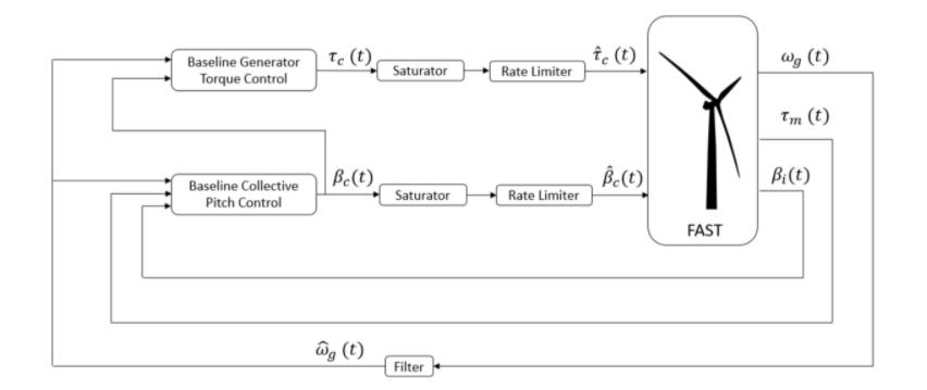
BecauseofhighproductioncostsofWTs,Computer AidedEngineering(CAE)hasbecomefundamentaltothewindenergy industrybecauseofitsabilitytogetreliableandaccuratesimulationsandresultsinthepreproductionstage.Thesoftware thatwasusedforthedevelopmentoftheprojectwasOpenFAST,whichisanopen sourceWTsimulationtooldesignedby theNRELthatcomputesthecoupleddynamicresponseofWTs.
International Research Journal of Engineering and Technology (IRJET)
Volume: 09 Issue: 04 | Apr 2022 www.irjet.net
e ISSN: 2395 0056
p ISSN: 2395 0072
Fig 9: FastusedinControlSystem
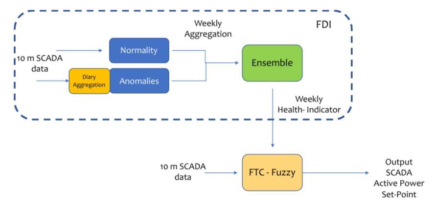
5.2 FAULT DETCTION AND TOLERANT CONTROL DIAGRAM
Toeffectivelyintroducefault tolerantcontrolofaSCADAsolutionwithoutgettingintotheparticularcontrolloops,the subsequentarchitecturewasproposed.
Fig 10: HighLevelArchitecture
ThemainblocksconformingtothisPassiveFTCweretheFaultDetectionBlockandtheFault TolerantControl.Theinput wasthe quality 10 min SCADAdata,usuallyacquiredusingan Open Platform Protocol (OPC).Forthe faultdiagnosis, we proposed a solution combining Normality (Regression) Models and Anomalies using ensemble learning. The fault diagnosisoutputwasweeklyhealthindicatorsthatfedthesymboliclogic.
The inputs were health indicators (on a weekly basis) and 10 minute SCADA data. The 10 min SCADA data was wont to finetunetheoutputduringtheweeklyoperation.
5.3 HEALTH INDICATORS
Anunmonitoredhealthindicatorwasusedtodeterminetheinitialfailurestate.Theseindicatorswerecollectedweeklyto enable early stage error detection. Here it was used as an input to a fault tolerant control strategy. The health indicator consisted of a regression algorithm and an anomaly algorithm. We then used ensemble learning to combine these two indicatorstoimprovesensitivityandaccuracy.
6. SOFTWARE
The MPLAB IDE is an integrated development environment that provides development engineers with the flexibility to develop and debug firmware for various Microchip devices. The MPLAB IDE is a Windows based Integrated Q DevelopmentEnvironmentfortheMicrochipTechnologyIncorporatedPICmicrocontroller(MCU)andaspicdigitalsignal controller(DSC)families.IntheMPLABIDE,youcan:
International Research Journal of Engineering and Technology (IRJET)
Volume: 09 Issue: 04 | Apr 2022 www.irjet.net
e ISSN: 2395 0056
p ISSN: 2395 0072
Createsourcecodeusingthebuilt ineditor. Assemble,compile,andlinkyoursourcecodeusingavarietyoflanguagetools.TheMPLABIDEcomeswithanassembler, linker,andlibrarian.TheCcompileris availablefromMicrochipandotherthirdparties.Monitortheprogrammerflowin real time with a simulator like MPLAB SIM or an emulator like MPLAB ICE to debug the executable logic. A third party emulatorthatrunsontheMPLABIDEisalsoavailable
Taketimingmeasurements.
ViewvariablesinWatchwindows.
7. CONCLUSION
The SCADA system is commonly used to detect issues in wind turbine systems, although it takes a lot of labor and time. Artificial intelligence (AI) is utilized to improve the program's efficiency and power. The Naive Bays method is a sophisticated machine learning approach for fault analysis. Naive Bays classifiers are a subset of simple "probabilistic classifiers" found on Bays' theorem and strong feature independence conjecture. They're one of the most basic Bayesian network models, but when combined with kernel density estimation, they can achieve higher levels of accuracy. As a result,internalandcircuitdefectscanbeidentifiedinashortamountoftime.
This research offers an intelligent fault diagnostic method based on an artificial neural network and an expert system to increase the accuracy of fault diagnosis of offshore floating wind turbine generators. According to the pre built database andreasoningframework,thediagnosissystemanalysesandcalculatesthedatacollectedfromthesensor.Incomparison tothetraditionalfangeneratorfaultdiagnosissystem,itcaneffectivelyimprovethefaultdiagnosisefficiencyandaccuracy ofthe floatingfangenerator system,aswell asfeedthe diagnosis resultsback totheuserin real time,greatlyimproving equipmentmaintenanceefficiencyandloweringequipmentmaintenancecharge.
8. REFERENCE
[1] Renewable Energy Institute, “Statistics Global Energy”. Available online: https://www.renewable ei.org/en/statistics/international/(accessedon12August2021).
[2]. Sheng, S. Report on Wind Turbine Subsystem Reliability A Survey of Various Databases; National Renewable EnergyLaboratory:Golden,CO,USA,2013.
[3]. Reder, M.D.; Gonzalez, E.; Melero, J.J. Wind turbine failures tackling current problems in failure data analysis. In JournalofPhysics:ConferenceSeries;IOPPublishing:Bristol,UK,2016;Volume753,p.072027.
[4]. Faulstich, S.; Hahn, B.; Tavner, P.J. Wind turbine downtime and its importance for offshore deployment. Wind Energy 2011, 14,327 337.
[5].Statista .2021. Available online: https://www.statista.com/statistics/268363/installed wind power capacity worldwide/(accessedon12August2021).
[6].Gao,Z.;Liu,X.Anoverviewonfaultdiagnosis,prognosisandresilientcontrolforwindturbinesystems. Processes 2021, 9,300.
[7].Hart,E.;Clarke,B.;Nicholas,G.;Amiri,A.K.;Stirling,J.;Carroll,J.;Dwyer Joyce,R.;McDonald,A.;Long,H.Areview of wind turbine main bearings: Design, operation, modeling, damage mechanisms and fault detection. Wind Energy Sci. 2020, 5,105 124.
[8].Rashid,H.;Khalaji,E.;Rasheed,J.;Batunlu,C.FaultPredictionofWindTurbineGearboxBasedonSCADADataand Machine Learning. Proceedings of the 10th International Conference on Advanced Computer Information Technologies(ACIT)AdvancedComputerInformationTechnologies(ACIT),Deggendorf,Germany,16 18September 2020.
© 2022, IRJET | Impact Factor value: 7.529
9001:2008
Page3589
International Research Journal of Engineering and Technology (IRJET)
Volume: 09 Issue: 04 | Apr 2022 www.irjet.net
e ISSN: 2395 0056
p ISSN: 2395 0072
[9]. Habibi, H.; Howard, I.; Simani, S. Reliability improvement of wind turbine power generation using model based faultdetectionandfaulttolerantcontrol:Areview. Renew. Energy 2019, 135,877 896.
[10].Acho,L.;Rodellar,J.;Tutivén,C.;Vidal,Y.PassiveFaultTolerantControlStrategyinControlledWindTurbines.In Proceedingsofthe3rdConferenceonControlandFault TolerantSystems(SysTol),Barcelona,Spain,7 9September 2016.
[11].Pozo,F.;Vidal,Y.Wind turbinefaultdetectionthroughprincipal componentanalysisandstatistical hypothesis testing. Energies 2016, 9,3.
[12]. Hosseinzadeh, M.; RajaeiSalmasi, F. Analysis and detection of a wind system failure in a micro grid. J. Renew. Sustain. Energy 2016, 8,043302.
[13]. Zaher, A.S.A.E.; McArthur, S.D.J.; Infield, D.G.; Patel, Y. Online wind turbine fault detection through automated SCADAdataanalysis. Wind Energy 2009, 12,574 593.
[14]. Gibert, K.; Marti Puig, P.; Cusidó, J.; Solé Casals, J. Identifying health status of wind turbines by using self organizingmapsandinterpretation orientedpost processingtools. Energies 2018, 11,723.
[15]. Beretta, M.; Julian, A.; Sepulveda, J.; Cusidó, J.; Porro, O. An Ensemble Learning Solution for Predictive MaintenanceofWindTurbinesMainBearing. Sensors 2021, 21,1512.
[16].Odgaard,P.F.;Stoustrup,J.Abenchmarkevaluationoffaulttolerantwindturbinecontrolconcepts. IEEE Trans. Control Syst. Technol. 2014, 23,1221 1228.
[17].Vidal,Y.;Rodellar,J.;Acho,L.;Tutivén,C.ActiveFaultTolerantControl forPitchActuatorsFailuresTested ina Hardware in theLoopSimulationforWind Turbine Controllers. Proceedings ofthe 23rdMediterraneanConference onControlandAutomation(MED),Torremolinos,Spain,16 19June2015.
[18]. Badihi, H.; Zhang, Y.; Hong, H. Wind turbine fault diagnosis and fault tolerant torque load control against actuatorfaults. IEEE Trans. Control Syst. Technol. 2014, 23,1351 1372.
[19]. Casau, P.; Rosa,P.; Tabatabaeipour, S.M.; Silvestre, C. Faultdetection and isolation and fault tolerant control of windturbinesusingset valuedobservers. IFAC Proc. Vol. 2012, 45,120 125.
[20]. Kim, J.; Yang, I.; Lee, D. Control allocation based compensation for faulty blade actuator of wind turbine. IFAC Proc. Vol. 2012, 45,355 360.
Factor value: