DYNAMIC ANALYSIS OF SHEAR BUILDING AT DIFFERENT LOCATIONS IN DIFFERENT SEISMIC ZONES USING CYPECAD
Chennabasava C
Department
Department
and Mahesh (M. Tech, B.E in Civil Engg)2
Ballari, Karnataka, India
RYMEC, Ballari, Karnataka, India
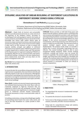
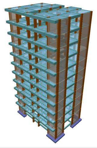
Abstract - Simple kinds of structure were presumably utilized to provide protection from the sun, wind, and rain at the beginning of the building's history. According to archaeological and anthropological research, the history of constructed forms and building enclosures has furthered this knowledge that history helps explain distinct types of structures, uniqueconstructionprocesses,andabroadvariety ofmaterialsusedtoday. Thecurrent researchinvolves adding a shear wall to an RCC structure in order to acquire the requisite stability, strength, and stiffness to withstand horizontalstresses(Seismicload).CYPECADwasusedtoassess a regular shaped with or without a shear wall. The outcomes of the Response spectrum approach employing CYPECAD are investigated. With the use of a structural shear wall system, the planned building is designed to decrease displacement. Storey displacement, storey drift, and story shear are the factors investigated in this work.
Key Words: Storeydisplacement,storeyshear,lateralforces, shearwall,seismicarea
1. INTRODUCTION
Inrecentdecadestheoneproblemarisingnationwideisthe rapidincreaseinpopulation,thisissuehoweverdirectlyand indirectlyimpactsontherateofconstruction.Althoughthe constructionisspreadinginhorizontaldirection,duetothis issuethereisanurgeforconstructiontoincreaseinvertical directionalsoresultinginapartments,skyscrapersandother multi storeybuildings.
Shear Wall: Areinforcedconcreteframedconstructionthat canwithstandlateral pressureslike wind. Shearwalls are commonly employed in high rise structures that are subjected to lateral wind and earthquake stresses. Wind pressures become more significant as a structure's height grows in reinforced concrete framed constructions. Horizontalmovementorswayisrestrictedundercodesof practice.
Inbuildingconstruction,astrongverticaldiaphragmcapable of transmitting lateral loads from outer walls, levels, and roof to the base foundation in a plane parallel to their surfaces.

CYPECAD: Homes provide us with both living space and shelterfromtheoutdoors.Systemicstyleisatechniquethat useseconomyandsimplicitytoproduceasafe,operational, andlong lastingfoundation.Commercialtrainingisvitalto thedevelopmentofpracticalknowledgeabilitiesforevery designer in the current environment. Structural loads, circumstances,andstrongpropertiesmustallbeknownin ordertoconductanaccuratestudy.Theoutcomesofsuchan analysis included support actions, pressures, and displacements. The purpose of this study is to provide a system that is secure, serviceable, long lasting, and cost effective. The created building should be able to resist exceptional loading situations. Under normal working conditions, cracking and fracture must not exceed the structure'scapability.Theseismicweight,windload,dead weight, and living load of the building are calculated and imposed.Themaximalsafetyfactorshouldbeconsideredin load cases to ensure that the building does not fail due to natural hazards or overloaded. IS codes are utilized in manualcomputations.
Meaning of CYPE
ENGLISH
CALCULOS CALCULATION
AND P POTOLOGY
OF (Scanning)
ESTRUCTURAS STRUCTURES
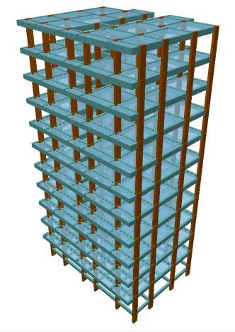
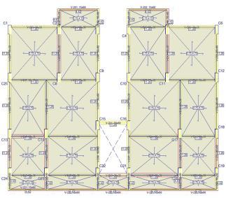
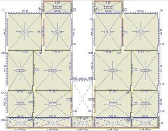
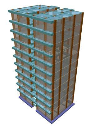
6. BUILDING MODELING
kN/m
:1.5kN/m
:
Type II &
isconstructedforregular
AnalysetheregularbuildingusingCYPECAD.
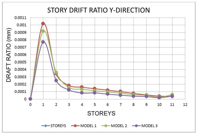
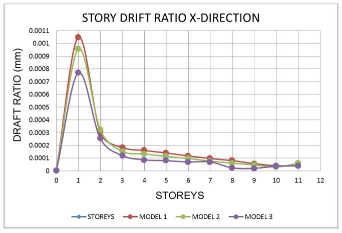
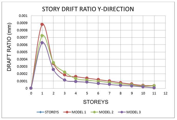
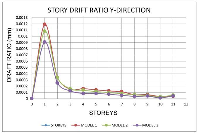
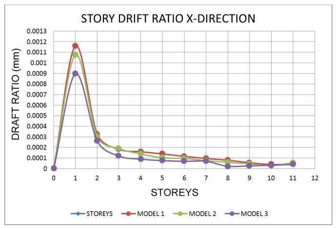
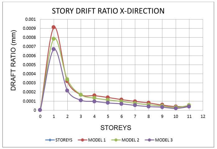
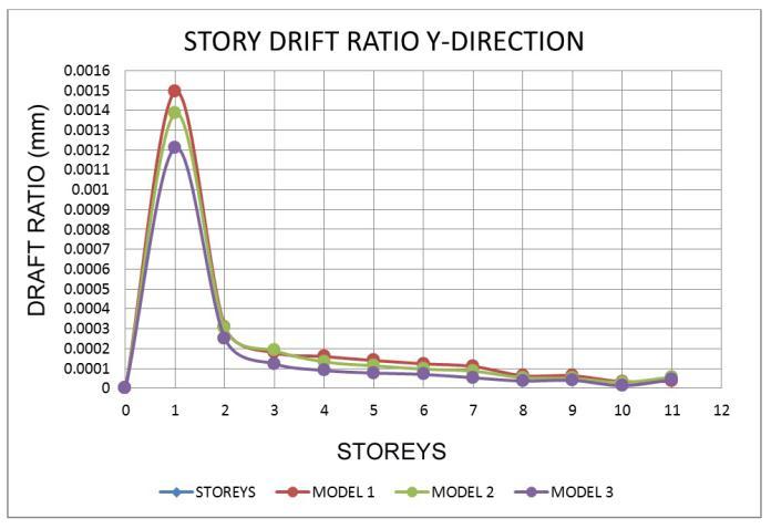
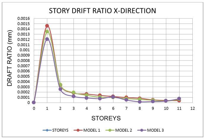
7.2 Storey Drift Ratio
The
Chart
Chart
Chart
Thecurrent
Following are the
carriedout:
aims
better
in
from
• Shear walls significantly increase the rigidity and strengthoftheframestructure,henceignoringthem during structure analysis and design will result in failureduetostiffnessirregularity.
• Symmetry in position of shear wall in plan is a key factortoobtaindesirableperformanceofshearwall structure.
• Increment in number of storeys make the building frame more vulnerable and therefore shear wall becomes a necessity in high rise buildings to save damageduetoearthquake.
• Asthenumberofstoreysincreases,lateralmovement increases, resulting in increased storey drift. As a result, we've discovered that high rise buildings withoutshearwallsarevulnerabletocollapseunder seismic stresses, posing a risk to both life and property.
• Thestructurewiththeshearwallatthecornershasa higherbaseshearthantheotherstructure.Asaresult, shear walls at corners in more earthquake prone placesareviable.
• Whenastructurehasashearwallatthecorners,the storeydisplacementislowerthanwhenthebuilding doesnothaveashearwall.Asaresult,itispossibleto constructashearwall.
Shearwallshaveawiderangeofbenefits,including:
• Because of their strong rigidity in their own plane, theycaneffectivelyreduceundesirabledeflection.
• Act as fire compartment walls, with the ability to withstand the effects of lateral wind on the superstructureandearthmotiononthesubstructure.
Shear walls, on the other hand, are more time intensive andlessexactinmeasurementsthansteelworkforbelow tenstories).Ingeneral,RCwallsdevelopsufficientstiffness and strength to withstand loading from the side of building. These walls have a low degree of ductility and may not be able to withstand the energy necessary in a majorearthquake.
8. CONCLUSIONS
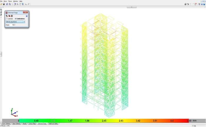
Theconclusionsaboutdynamicresponsespectrumanalysis of RCC Structural frame with or without shear wall are drawnfromtheresults.
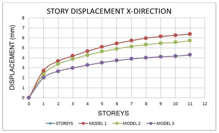
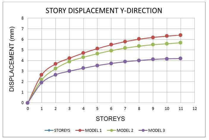
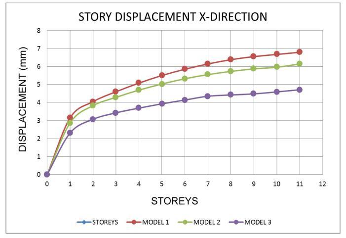
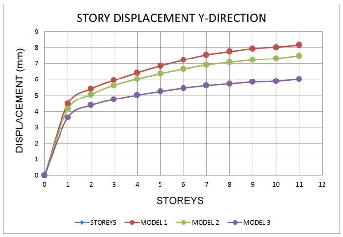
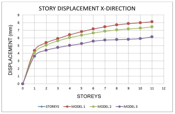
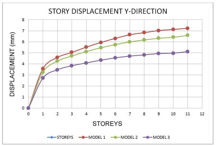
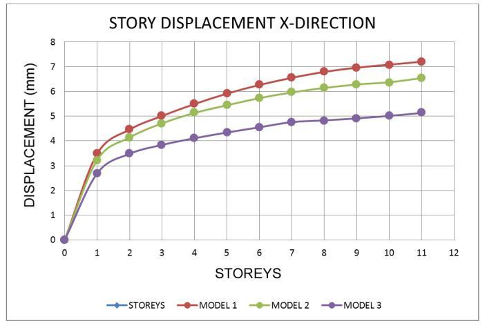
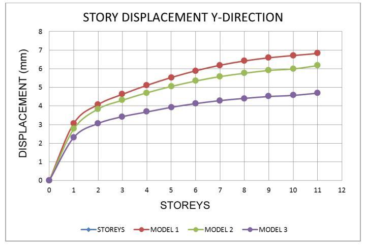
• Inallzonemodels,thedisplacementatthetoplevel ishigher.
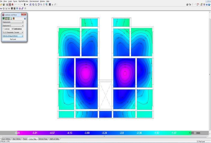
• Models with a shear wall reduce movement, resulting in models with the least displacement whencomparedtoothermodels.
• Asthenumberofseismiczonesincreases,sodoes the number of displacements in the response spectrumwayofanalysis.
• Whencomparedtoothermodels,themovementsin theshearwallmodel 3areless.
• InzoneV,thepercentagereductionformodel 1and model 2 is 8.49 % and 9.86 %, respectively, comparedtotheleastdisplacementmodel,model 3.
International Research Journal of Engineering and Technology (IRJET) e ISSN: 2395 0056
Volume: 09
• Fromthelowesttothetopstory,thedisplacement risessteadily.
• In models 1 and 2, the story drifts gradually decreased.
• For all zones, the Drift ratio is lowest in model 1 andmodel 2intheXandYdirections.
• For all earthquake regions, the proportion of increaseindisplacementanddriftratioisthesame.
• The base shear values are increasing in all zones, withzoneVhavingthegreatestbaseshearvalue.
• Model 3hasthehighestbaseshearofallthezones.
ACKNOWLEDGEMENT
p ISSN: 2395 0072
Prof.Mahesh (M.Tech,B.E)


DepartmentofCivilEngineering, RYMEngineeringCollege, Ballari,Karnataka,India
Special
guideProf.Mahesh, AmarnathaSN,FEDesingsBangalore
REFERENCES
[1]
[2]
[3]
456 2000forPlainandReinforcedConcrete Code ofPractice.
875 PartI(1987):CodeofPracticeforDesignLoads (DeadLoads).
875 Part II (1987): Code of Practice for Design Loads(ImposedLoads).
[4]
[5]
875 Part III (2015): Code of Practice for Design Loads(WindLoads).
875 Part IV (2016): Code of Practice for Design Loads(WindLoads).
Reinforced
by S S BHAVIKATTI
ChennabasavaC
Departmentof
RYMEngineeringCollege, Ballari,Karnataka,India