Increasing Downforce In High-Speed Vehicles Using Wheel Rotation
Downforce, or downward lift force, is created by a vehicle's aerodynamic properties. The vertical force on the tires is increased by downforce, resulting in a higher grip. The purpose of the downforce on a fixed wing aircraft'shorizontal stabilizer is to maintain longitudinal stability and allow the pilot to direct the plane in pitch. Formula 1 vehicles are propelled off the ground by the same process that propels airplanes. This impact is referred to as "aerodynamic grip," as
to "mechanical grip," which is governed by the vehicle's mass, tires, and suspension. Passive devices can only increase downforce by increasing aerodynamic drag (or friction). Downforce increases in direct proportion to the square of the vehicle's speed and requires a specific minimum speed to have a noticeable effect. Some cars had relatively unstable aerodynamics, resulting in significant downforce fluctuations with minor changes in the angle of attack or vehicle height. In the worst case scenarios, such as when passing over a bump or slipstreaming over a crest, this can result in lift rather than downforce. Sucking air beneath the car creates a low pressure region beneath the vehicle, and the sucked air is sent to the back end low pressure region of the wake. As a result, a lot of work has already been done to improve this downforce, employing some traditional methods and their variations. However, because boosting downforce always increased the coefficient of drag, we made a change to the back wheels
1. INTRODUCTION
Carstaysonthegroundbecauseofdownforce.Thenegative liftisknownasdownforce.Inotherwords,thesamephysical lawthatallowsplanestosoarupwardalsoforbidscarsfrom flying. This is the shape of an aircraft's airfoil, which generatesliftbycreatingalow pressureareaontheupper side and a high pressure area on the lower side. Lift is developedbythepressuredifference.Whatiftheshapeis flipped around? Due to this, there will be more pressure upwardandlesspressuredownward,whichinturngivea negativelift.Downforceisthetermforthisnegativelift.Asa result, the car's wing is bent in the opposite direction, causingtheairdeflectedbeneathittoflowathigherspeeds andgeneratealowerpressureareathanontop.Theforce thatpushesthecardownisreferredtoas"Downforce,"and itimprovesgrip
In1977LotusteamownersColinChapmanandPeterWright introducedtheirfirst‘WingCar’.Theyhaddiscoveredthat byshapingthewholecarlikeawingtheycouldspeedupthe airflowunderneathitrelativelytotheairflowoverthetopof thecar.Thus,creatingavacuumunderthecar,itwouldbe pulled down to the track creating a huge amount of downforce. An extra benefit to this way of creating downforceisthattherewouldbelessdragfromthefront andtherearwingsothecar’sspeedonthestraightswould be less compromised. The Lotus 78 was having reliability issues in the beginning but those were solved during the 1977 season, by fine tuning the ‘Venturi Tunnels’ responsible for creating the increased downforce, and in 1978 Lotus won 4 out of the first 7 races. Cox had the wonderful idea of using a fan not just to create a ground effect,butalsotokeeptheenginecool.Becausemostother builders were completely unaware of the reasons for the Lotus'success,GordonMurrayofBrabhamwastheonewho finally figured out what brilliant solution Chapman had devised to generate such massive downforce. However, because of the bigger Alfa Romeo Flat 12 engine in their BrabhamBT46,the'VenturiTunnels'requiredtoachievethe desiredgroundeffectwerenotachievableduetoashortage of space under the back of the car. Murray was brainstorming with David Cox another way to create a vacuumbeneaththecar.Theywereinspiredbya Can Am sports car known as the 'Sucker Car,' the Chaparral 2J. In 1970,Chaparralcompetedwithtwofansinthebackofthe car, each using a small two wheeled engine, pumping air behind the car, resulting in decreased pressure and increased downforce. Murray intended to try a similar conceptwithBT46afterseeinghowfastChaparral2Jwas. Theworkmadewasusinganactivedevicetoincreasethe downforceforthemodelswerebannedanduseofanactive devicetoincreasethedownforcewasbannedinF1racing. Butstill,passivedevicescanbeusedtocreatethiseffect.And givingpropellerbladestructuretothewheelwillfulfillthis need.
1.1 LITERATURE SURVEY
Thissectiondiscussesinbrief,variousstudiesconducted byresearcherswithregardstotheaerodynamicsofFormula Oneracecars,andthevarioustechniquesusedtooptimize thebodyworkanditscomponentstoreducelaptimes.The aerodynamics of race cars talks about the forces on the vehicle at high speed. The aerodynamics of racing cars is similartotheaerodynamicsofanairplane.Whilethemain

purposeofthecomponentsofanaircraftistogeneratelift, most of the components on a racing car are designed to create downforce, i.e., lift in a negative direction. Aerodynamicsallowtonsofdownforcetobecreatedonthe front and rear axles, without increasing the weight of the body;thus,increasingtireadhesion,which,inturn,allowsthe racecartonegotiateaturnatahigherspeed.
Downforce aids traction as well; however, the improvementisnotaslargewhencomparedtobrakingor cornering.Theaccelerationislimitedbytheenginepower available.Whenthecarturnsandbrakessimultaneously,a significantpointtobenotedisthateventhoughtheresultant force available to the tires is equal to pure cornering or brakingforce,theindividualcapacitiesofthecomponentsof theresultantforce(corneringandbrakingforce)arelesser.It canbeconcludedthatbrakingwhilenegotiatingaturnwill reduce the cornering force, leading to an unprecedented slide. Thus, levels of downforce have to be increased sufficientlytopreventtheslidefromoccurring.Theoretically, thehigherthedownforceactingonthecar,thefasteritcan maketheturnwithoutsliding.
Nothing comes free of charge though. The penalty for excessivedownforcecomesintheformofincreaseddrag[3]. Hence, the main task for aerodynamicists in designing the bodyworkistooptimizethebalancebetweendownforceand dragforcescreatedtoobtainthefastestpossibletimearound aracetrack.Aerodynamicsofracecarsnotonlyinvolvesthe creationofdownforcebutalsoincludesareassuchasairflow toengineboxandradiators,coolingofbrakes,limitingfuel sloshing,thereleaseofexhaustgases,etc.However,thiswork primarily focuses on the issue of obtaining optimized downforceanddragvaluesforF1cars.
In[6]Motorsportsareallaboutmaximumperformance, tobethefastestisabsolute.Thereisnothingelse.Tobefaster youneedpower,butthereisalimittohowmuchpoweryou can put on the ground. To increase this limit, force to the groundmustbeappliedtothewheels.Weightgaincando this, but weight gain makes it worse and requires more energy.Soweneedarealisticweight,wecallitdownforce and get in the airflow near the car. The wings have been shownsolelytogiveasenseofproportion.
Usually, the word "lift" is used to describe any kind of aerodynamicallygeneratedenergythatworksinspace.This isgivenanindication,either"positivelift"(top)or"negative lift"(bottom)intermsofitspath.In groundaerodynamics (cars, bicycles, etc.) the word "lift" is often avoided as its meaningisalmostalwaysdefinedasgood,thatis,liftingacar off the lane. The Downforce should always give a sense of negativeforce,i.e.,togetmoretractionforce.
The desire to continue to increase the adhesion of the wheelsledtoamajorshiftintheconstructionofracecars, theuseofanimproperliftor'downforce'.Asforthetires,the adhesionofthesidesisalmostequaltotheloadonit,orthe
friction between the wheel and the road, adding low aerodynamic strength to the weight component improves adhesion.Thedownforcealsoallowstirestotransmitmore powerwithoutwheelrotation,whichincreasesthepotential foracceleration.Apartfromtheaerodynamicdownforceto increasegrip,modernracingcarsaresopowerfulthatthey canspinwheelsortravelatspeedsinexcessof160km/h.
Aspoilerisasimpleplateplacedsomewhereonthebody ofthecarsothatitcanobstructor"spoil"theflowaroundthe vehicle,allowinga controlled separation of the flow at the desiredlocation.Thisisdonebecausefast,smoothairflow leadstopositivelift,soimpedingthisfloweitherreducesor perhapscancelsliftaltogether.
Arearspoilerisaplatemountedattherearofthevehicle andinorderforittobeconsideredaspoiler,theplatemust beintegrallyattachedtothebody.Ifthereisspacebetween theplateandthebody,itisconsideredawing.Thespoiler causesasplitinthebackofthecar,causingadisturbancejust beforeflow,thisdistortioncausestheflowtoslowdown,thus reducingtheminimum pressure inthearea infrontofthe spoiler. Therefore, the elevator in the back of the car is removed. When properly designed, the rear spoiler will createdownforceonthebackofthecar.
The diffusers, behind the wings, are the tools that are basicallyusedtocreateinflationonthebackofaracecar.In them, the Bernoulli equation is used as we do with the venturitube.Itcanbeseenthatinaventuri,thesquareof pressure and velocity is inversely proportional. Thus, a diffusercanhelpreducethelowpressureunderthecarto increasespeed.
Atthefrontofavehicle,themainsourcesofdownforce are theunderbodywiththefront spoiler (alsoknown asa spoiler,dam,orsplitter),cleats(alsoknownasdivingplates), vortexgenerators,andfrontdiffusers.
Spoilers, dams, or splitters are better explained by followingthelink.Theyreducethegapbetweentheground andthevehicle(facingittowardsthesideofthevehicle)by blockingasmuchairasitcangetunderthevehicle,usinga spoiler on a vehicle with very turbulent airflow on a non smooth flooredvehiclecanresultinlessairpassingthrough allelementsofthevehicle'sfloor,significantlyreducingdrag andalsoreducinglift.(andmaybealittledownforce)inthis case.
Duckandthevortexgeneratorindetail.Asmallfininthe frontcornerofacar.Althoughtheinclinationofthisplateis minimal,itcreatesdownforceinthefrontofthevehicle.The samedevicecanbeusedinotherpartsofthecar.However, caremustbetakentoensurethatthevortexontheleading edgedoesnotinterferewiththeoperationoftherearwingor other aerodynamic devices. This dive plate is sleeker than anyotherandistoosmalltogenerateasmuchdownforce. Instead,itisusedtoadjustcarhandlingbeforetherace.
In[1]wecanseeToachievetheoptimizeddragforthe vehicle,theresearchisbeingcarriedoutoncertainadd on aerodynamicdevicestoreducetheresistanceofferedbywind andimprovetheefficiencyofthevehicle.Inthisresearch,the effects of various aerodynamic devices like the rear wing, spoiler,diffuser,andfinsareexaminedandthechangeinthe coefficientofdragisinvestigated.
Spoilersareoneofthemostwidelyusedandimportant aerodynamic devices in the automotive industry. Its main purpose is to help reduce drag by "disturbing" unwanted airflowandsequencingtheairflow.However,theactualuse ofthespoilerisnoticeableathighspeedsaboveabout120 km/h. Commercial vehicles typically use it to enhance the appealofvehicledesignsthatofferlittleornoaerodynamic advantage. So basically, high performance cars apply it to achieve higher speeds. The low pressure area behind the vehicle is reduced, which creates less turbulence and consequentlyreducesdrag.
Theultimateaimofeveryracecardesigneristoimprove thelaptime,withoutcompromisingsafetyandotheraspects. To achieve this objective, the most predominant factor is cornering ability at high speed. During cornering, the cars havetoreducetheirlongitudinalaccelerationtocompensate for the lateral acceleration i.e., it has to slow down while corneringtoavoidslidingordeviatingfromthedesiredpath, asthetractionprovidedbythetireislimitedforagivenload. One such way to improve the cornering ability, ultimately improvinglaptime,isbyimprovingthetractionofthetires by increasing the load acting on them. Resistance forces actingonthebodyaregenerallyoftwotypes:viscous and forced. Induced drag results from the creation of lift and viscous drag results from the boundary layer interaction betweenthebodyandthefluid(airinthiscase).Thus,the overalldragcoefficientforthefinalwingiscalculated.
The best way to increase the load on the tires when cornering is to increase the car's aerodynamic downforce coefficient to some extent (up to the critical downforce coefficient).Animportantfactorinreducingtheamountof resistanceisthepositiveeffectofthetimedelayduetothe decrease in muscle strength on the hip. [2] introduces a methodtodeterminethemostimportantdecelerationfactor ofavehicleonaspecifictrack.Significantreductionfactors are determined by a series of analytical statistics and simulations performed using OptimumLap software. The criticalcoefficientofdownforcefortheFSAE noaerocaron the Buddh International circuit is found to be 2.2 and the correspondinglaptimeis128.950whichisabout10seconds clear from the lap time by the initial setup without any aerodynamicdownforce.Goingfurtherthecriticalcoefficient, the lap time increases which is undesirable. So the aerodynamic add ons should be designed to reach the downforcecoefficientof2.2.
2. METHODOLOGY
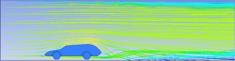
Thechallengeistodecreasetheliftthatiscreatedduetoair movingunderthecarandcreatinganundesirableliftforce. So,toeliminatethiseffectwheelshavebeenusedtoignore unnecessarypowerconsumption.Therotationofthewheel itselfcreatesasuctioneffectthatmakestheairunderthecar modeltomoveoutandcreatealow pressureareawhichin turnincreasesdownforcewithoutaffectingthefuelefficiency of the car as we used a passive device for the job. The air exhausted from the wheel will increase drag substantially duetoitsrotation.So,toignorethisincreaseindragfurthera coveringisgivenfortherearwheelandtwoholeshavebeen madetoguidetheflowtothelow pressurewakezonewhich ismadebehindthecar.Sothatitcanincreasethepressureat the rear end of the which further decrease the drag coefficient.
2.1 MODEL
Fordesigningthebasemodelcar,CATIAV5wasusedand thebasicmodelwascreated.Thenthefilewasexportedfor analysisin.igsformatforAnsys.
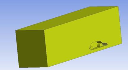
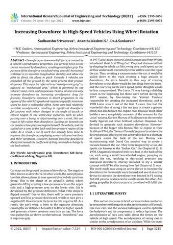
Fig 1:Basemodelcar
The three dimensional car model was imported to the ANSYS™workbench.ComputationalFluidDynamics(CFD) wascarriedoutintheFLUENTmodule.InDesignModeler, anenclosureisdevelopedofdimensions1500×300×600 mmtoformavirtualwindtunnel
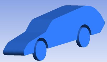
2.2 MESHING
AnappropriatemeshwasdevelopedusingANSYS™Mesh
was observed to be
domainandfineratthecontactregionwith
the
424,773 elementswereformedafterthemeshingwasdone.
showninFigure4.3.Atotalof591,978
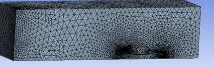
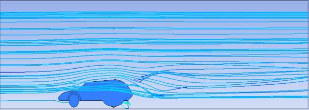
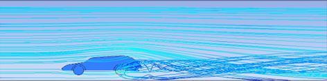
Fig 6:Streamlinediagramofcase2
All the designed car models with wheel conditions are simulated in ANSYS™ 21.0 Fluent. The results of the drag coefficientsobtainedarediscussedbelow:
2.3 BOUNDARY CONDITIONS
The fluent was set to work on double precision and solverprocessesweremadeto4.Duetoitsstabilityandease ofconvergence,theStandardk epsilonmodelwasselected asaturbulencemodel.
Table
v=50m/s
reference pressure
0Pa
2.4
The
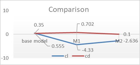
Chart -1:Graphicalcomparisonofcdandclofdifferent model
Theobjectiveofthisstudywastodevelopamethodology tocreatedownforcebycreatinglow pressureregionbelow the model. After providing a historical background of Downforce and developments in the field of race aerodynamicstoincreasedownforce,aliteraturereviewwas conductedtodevelopafocusareaforthisresearchstudy.
An introduction was provided for the basic boundary condition(Ansys)usedforsimulatingthemodelstogetcland cd value. A model was created in CATIA to start the simulation. Enclosure and other geometrical specifications weregiven.
AnAnalysisusingAnsyswasperformedtodeterminethe clandcdvaluesofdifferentmodelconditions.Theresulting bestclwas 0.26andthecdvalueforsamewasfoundtobe 0.1.
3. CONCLUSION
After getting more drag value in case 2 the wheel was givenacoveringoveritandtwoholestoguidetheflowtothe low pressurewakeregion.Theclvalueforcase3gotcloser totheoptimizedvaluethatis0.22andalsothedragvalue reducedfrom0.35to0.1
International Research Journal of Engineering and Technology (IRJET) e ISSN: 2395 0056
Volume: 09
REFERENCES
www.irjet.net p ISSN: 2395 0072
[1] DevangS.Nath*,PrashantChandraPujari,AmitJainand Vikas Rastogi, Drag reduction by application of aerodynamic devices in a race car https://doi.org/10.1186/s42774 020 00054 7.
[2] Brighton George, Jairesh J. V., Chithraiselvan G., Gokul NathS,DeterminationofCriticalDownforceCoefficient of a Vehicle for Optimum Aerodynamic Performance, e ISSN:2395 0056
[3] JosephKatz,“AerodynamicsofRaceCars”.
[4] DavidCox,“Brabhamf1‘fan car’bt46b”.
[5] SirFrankWilliams,“Downforce”.
©