
REVIEW OF THE ROLE OF JOINTS USAGE IN BRIDGE STRUCTURES

Bridges are very important connecting elements and backbone of highway infrastructure. Joints are used in bridge construction to accommodate the relative temperature movements in concrete, vertical movements due to loading conditions and movements due to shrinkage and creep effects in concrete. This paper tells about the role of joints usage in bridge structures. This paper reviews about different joints used in bridges of highways. It is also describing about various causes of failures of joints and the remedial measures.
2. LITERATURE REVIEW
1. INTRODUCTION
As we all know, concrete is important basic structural material that is very much susceptible to environmental conditions such as temperature. Seasonal temperature variation is causing the concrete to expand and contract. Duringthesummerseason,concretesurfaceswillundergo expansionandinthewinterseason,concretesurfaceswill undergocontraction.Theinternalstresseswhichdevelopin theconcreteduetotemperaturevariationscausingcracksin the structural elements. The concrete overall size can be changed because of the warping molecules of concrete subjected to temperature variation. In order to cater the thermal movements inconcretesurfaces ofbridges,joints arecommonlyused.Jointsareusedtoseparatetwoormore adjacentbridgeelements.Thejointsarenormallyweakest part and most vulnerable area in the bridge structure. Extremecareisneededinmonitoringofjointsinthebridges. Ifthejointswerenotproperlymaintainedanddesigned,the distress at bridge joints causing many maintenance problems,including spalling ofconcreteatthejoint edges anddamage ofpier caps/cappingbeams andotherbridge elements. The maintenance work of these joints at major bridgesbecomesveryhectic,sincethesemajorbridgesare subjected to heavy traffic loads all the time. So, the maintenance work cannot be done for longer time for the joints.Hencethejointsonabridgestructureshouldbewell designedtoperformsatisfactorily,foralongertimewithout requiringfrequentrepairorreplacement.Thejointsshould be well designed to cater free translation, deflection and rotation without causing damage to concrete wearing surfaceandcausingtroublesomenesstothetraffic.
AccordingtoLee1Constructionandbridgeexpansionjoints are invariably provided in all bridge decks at locations of structural discontinuity between the two elements. An expansion joint or movement joint can also be defined as deviceorsupportingmediumwhichsupportsthesurfacing, andprovidesarunningsurfaceforvehiclestopassoverit andfillingupthegapbetweentheadjacentbridgedeckand abutmentorareabetweentwoadjacentbridgedecks2.The bridgeexpansionjointsaredesignedinsuchawaythatthey used to allow continuous traffic over deck slabs of bridge structures accommodating movement, shrinkage, temperature variations on Reinforced and Prestressing Concrete, Composite and Steel structures. According to Raina3,anExpansionjointisalsocalledasContractionjoint because they accommodating movements in bridge deck spans and abutments. Expansion joint systems are integrated components designed to accommodate the repeatedcyclesofmovement.Properfunctioningofbridge expansion joint systems accommodates these movements without imposing significant secondary stresses on the bridge superstructure. According to Aziz4, Construction jointsaresometimesreferredascoldjointscanbedefinedas stopping positions in the concrete casting, and they are needed because of inconveniency to cast concrete, in one longcontinuousconcretingoperation.Theconcretequantity productionatsite,dependsonthenumberandcapacityof concretemixersavailableatsiteandtheformworkcapacity. The alternate stopping and resuming process of concrete castingoperationleadingtoinitiatetheconstructionjoints.
3.TYPES OF JOINTS
The joints provided in the bridgestructurecan befurther classifiedintothreetypesnamely(a)Constructionjoint(b) Expansionjoint(c)Contractionjoint. Expansionjointsare providedinbridgedecks,toallowthedeckmovementsdue to traffic loading and movements caused due to the shrinkage,creepandtemperaturevariationsintheconcrete and also Post tensioning shortening, dead load, live load, wind load, seismic load and structural settlements and deflections. The Expansion/Contraction joints can accommodate the movement ranging, from 30mm to 1000mm.Constructionjointsarethetemporaryjoints,often provided in concrete elements, when the concreting operationofanystructuralelementisstoppedtemporarily, duetohighheat,rain,andfailureofconcretingmachineries suchasvibratorandconcretemixer.Theconstructionjoints
areprovidedatthejunctionofabutmentandwingwalldue to the different levels. These joints are also provided in protectivewallssuchasretainingwalls.Thesejointscannot beprovidedatthesensitivelocationswhereshear,moment and bond stresses are high. The location of construction joints should be placed away from the supports. The construction joints can be either vertical or horizontal. In deck slabs, vertical type construction joints are provided. The open type construction joints are provided, in such a mannerthattheyshouldbesealedtoavoidingressofforeign substances into the concrete member. Shear keys (projections)arealsoprovidedwiththeconstructionjoints. Thecontractionjointisusedtotakecareofthedeformations oftheconcretememberduetochangeintemperature.The contractionjointcanbeprovidedforpartofthedeckslabfor smallerwidth.Expansionjointsoccupyfulldepthofbridge deckslabaswellasforlargerwidths.
4. CLASSIFICATION OF BRIDGE EXPANSION JOINTS
Thevarioustypesofbridge expansionjointswereusedin bridge structures. Some of them were discussed in this paper.
Buriedjoint
Asphalticplugjoint
Nosingjoint/compressionsealjoint
Cantilevercombortoothjoint
Reinforcedelastomericjoint
Elastomericjointinmetalrunners
Modularjointsincludingfingerandsliding plates.
Stripsealexpansionjoint
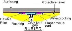
4.1 Buried joint
As the name implies, buried joints also known as simple joints, which are provided below the bituminous/asphaltic surfacing or wearing course. These jointsareusedtocatersmallmovementsandcanbeadopted for simply supported spans, up to 10m.In this joint arrangement,thewidthofjointiskeptas20mm.Asteelplate ofsize200mmwideand12mmthickofweldablestructural steel is placed symmetrical, to the centerline of joint to bridge the gap resting freely over the top deck concrete surface.BituminousorAsphalticwearingcourseislaidover thesteelplate.Elastomericpadcanalsobeprovidedinstead ofsteelplate.Thisjointallowslongitudinalmovementabout 20mmandverticalmovementof1.3mm.
Fig 1:BuriedJoint
4.2 Asphaltic plug joint
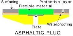
Thisjointisalsosimilartotheburiedjoint.Inthis joint,asphaltspecialadhesive(Binder)isappliedevenlyon thebottomsurfaceoftheexpansionjointgap.Asteelplateor closureplateisplacedatthemiddleoftheexpansionjoint gap,overtheasphaltspecialadhesivecoattomakethejoint firmandstrong.Heatresistantfoamcaulking/backerrodis availablebelowtheclosureplate.TheCrushedstonesheated athightemperatureranging from130oCto150 oCisfilled overtheexpansionjointgap.Finally,themeltingasphaltic plugjointispouredoverthecrushedaggregatesandjointis levelled.Thistypeofjointscanaccommodatelongitudinal movementupto40mmandverticalmovementupto3mm.
Fig 2:Asphalticplugjoint
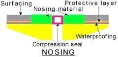
4.3 Nosing Joint/compression seal joint
Thisjointisalsocalledascompressionsealjoint.A compression seal made up of preformed chloroprene elastomer/extruded neoprene rubber/closed cell foamed jointsealerisprovidedatthecenterofexpansionjointgap with special adhesive binder. The seal can be used in this jointeitherofcompressedorpoured.Theedgesofjointgap arecoveredwithnosingmaterialmadeupofsteelnosingof anglesection.Thesteelnosingisanchoredtothedeckwitha suitable anchorage system. This type of joints can accommodate longitudinal movement up to 40mm and verticalmovementupto3mm.
4.4 Cantilever comb or tooth joint
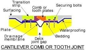
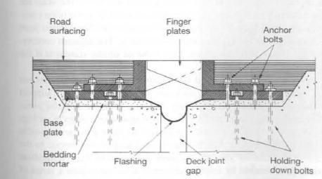
Inthisjoint,matingmetalcomborsaw toothplates areprovidedbymeansofapairofindividualcastaluminum alloysectionshavingone meterlengthandlaidoppositeto eachother.Aseriesofpairedcombsarearrangedtogeta singleunit,whichislaidovertheexpansiongapcoveringthe bridgewidth.Thecombsareeitherflamecutfromarolled steelplateorcastinaluminumalloy.Asmalltransitionstrip is available at the edges of expansion joint gap. The joint metal assembly is anchored to the deck, with the help of tensioncontrolfastenersoranchoredbolts/Securingbolts.A suitabledrainagemembraneisalsoprovidedatthebottom of expansion joint gap made up of elastomeric looped membrane or stainless steel water recovery membranes. Thistypeofjointscanaccommodatelongitudinalmovement upto25mmandverticalmovementupto3mm
looped membrane. This type of joints can accommodate longitudinalmovementupto80mmandverticalmovement upto3mm.
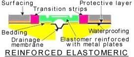
4.5 Reinforced Elastomeric Joint
It is a prefabricated mat joint, comprising an elastomerwithorwithoutbondedmetalplates.Thisjointis providedwithelastomericunitreinforcedbymeansofmetal plates.Thisjointassemblyisthenfixedtothebridgedeck with fixing fasteners or bolts which are sealed with resin plugs.Thisjointcanaccommodatemovementbytheaction ofsheardeformationofelastomerandopeningandclosing of elastomeric grooves at upper and lower surface. Asmalltransitionstripisavailableattheedgesofexpansion jointgap.Asuitabledrainagemembraneisalsoprovidedat thebottomofexpansionjointgap,madeupofelastomeric
Fig 5:ReinforcedElastomericjoint
4.6 Elastomeric joint in metal runners
This joint is a prefabricated joint comprising an elastomeric seal which is fixed between metal runners or metalrails.Themetalrunnersunitshallbeeitherofsingle element or multi element. The elastomers are provided betweenthegapsofmetalrunners.Multiplemetalrunners are used to accommodate large movements. In this joint, outer rail connectivity to the deck slab is provided by reinforcement.Thetransitionstripisusuallynotprovidedin thisjoint.Sealantisactingasatransitionstrip.Thistypeof jointscanaccommodatelongitudinalmovementupto80mm andverticalmovementupto3mm.
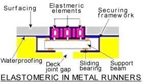
Fig 6:Elastomericinmetalrunners
4.7 Modular joints including finger and sliding plates
Modular joints are provided as bridge expansion joints in situation where accommodating of large longitudinalmovementisneeded.Theoveralljointsetupis oftwocategories.Inthefirstjointsetup,jointassemblyis constructed with special steel sections and with suitable elastomers placed in between them. In the second joint setup, called as finger type expansion joints like the cantilever comb or tooth joint, where open type sliding platesarelaidovertheexpansiongap.Thefingersaremade with rectangular cross section. The sliding plates are providedbymeansofapairofindividualcaststeelsections andlaidoppositetoeachother.Thisjointcanaccommodate movementupto160mm.
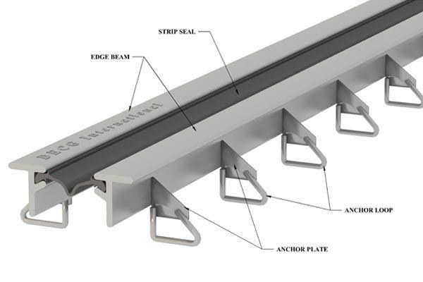
Strip seal expansion joint
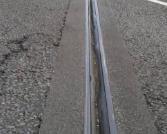
This type of joint is widely used in Reinforced concrete T beam cum deck slab. This joint is used to accommodate medium movement ranging from 40mm to 50mm for medium span bridges. This joint assembly is providedwithtwoedgebeamsmadeupofextrudedorhot rolled steel section or cellular steel section at the sides of expansionjointgap.Thegapofexpansionjointissealedwith theelastomericsealingelementorrubberglandtoprovide water tightness to the joint. The edge beam is usually supportedwithsteelanchorloopandanchorplatewhichis anchoragetothedeckslabreinforcement.
accommodate little movement too. It is not desirable to provide open joints. But sometimes, open joints are also providedinbridgedeckswitharmoranglestoprotectdeck slabs. The open surfaces of joint should be sealed with sealants/fillers and with special concretes such as Ultra High PerformanceConcreteandLatexModifiedConcreteto arrest the entering of foreign substances. The mixture of bitumenandcementwithequalproportionscanalsobeused asafillermaterialinfillinggapsofthejoints
6. COMMON DEFECTS ENCOUNTERED IN THE JOINTS
Thedefectsordamagesoccurringinjointsareduetoseveral reasons. It may be of poor materials used in joints, poor workmanship, inadequate supervision during joints installation operation, inadequate periodical maintenance etc and also by improper installation of joints without strictlyfollowedinstallationprecautionsaslaiddownbythe manufacturers
6.1 Overloading
The overloading due to single axle trucks causes heavyloadimpactovertheexpansionjointsandreducesthe serviceabilityofjoints.
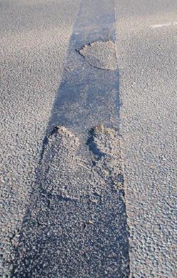
6.2 Rutting/breaking of wearing surface
Thisdefecthappensinbothopenandclosed/buried joints.Incaseof,closedjointsduetodeckmovement,cracks areopeningupinthevicinityofjointsurfaces.Continuous vehicleimpactandwaterpenetrationmayfurtherdamage thecracksleadingtoruttingofwearingsurface.Thewearing surfaceiseitherconcreteorBituminous/Asphalt.Incaseof openjoints,whentheasphalt/bituminouslevelisbelowthe levelofjointlevel,heavythrust/impactispossibleoverthe jointsandleadingthejointstodislodge
5. LONGITUDINAL JOINTS
Apart from the joints discussed in previous section, longitudinaljointsarealsousedinbridgedecks.Thesejoints are suitably provided in bridge decks laterally and longitudinally. The riding surface of Reinforced concrete bridge decks, are subjected to severe shrinkage cracks, duringclimaticconditioneventhoughsurfacereinforcement isprovidedinwearingcoats/surfaces.Theshrinkagecracks developedafterconcretingoperation,shouldbeavoidedas far as possible. To avoid those cracks and also to provide non slippery surface, top finished concrete surface is brushed with either brooms or sponges. The problem of arisingoutofthesecracksisnowadaysbecomecommon,in bridges constructed in our country. The joints shall be constructed by sawing the top concrete. The joint groove may be cut after the final set of concrete. This joint can
Fig 9:Ruttingofwearingsurface
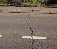
6.3 Improper injection of sealants into cracks
Wheneverthecrackgrowthisseenoverthewearing surfacesofburied/Closedjoints,thenthecrackdevelopment
Leakage of joints
Leakage
ingress
of
6.6 Joint vegetation
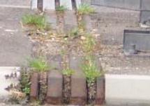
The
inthe
This
Loss of material from joint
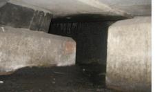
This
thiscase,asAsphaltic
mostlyinasphaltic
materialcomesoutofthe
intheformofeitherbinderoraggregates.Sometimes, flow of binder
the adjacent road surfacing is also possible.
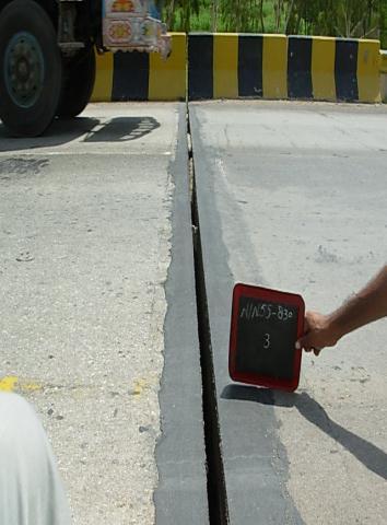
Debris buildup in the seal
material
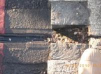
Breaking up of other materials
7. REMEDIAL MEASURES
Thefollowingarethekeypointstobefollowedinrectifying thedefectsinthejoints.
The top levels of joint should be kept below the existingelevationofasphalticwearingcoursebyat least 2mm to 3 mm. This procedure is to be followedinordertoaccommodatethesettlements inthewearingcourse.
The thickness of deck slab can be increased by at least 2 inches for better installation of the joint assembly.
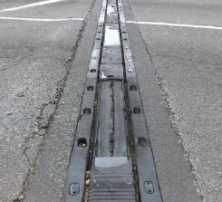
Remedial workscan becarried out in the form of fillingjointgapswithsealants,arrestingthecracks andreplacethedamagedcomponentsofjointsand fixing the joint fixtures for the missed/damaged jointfixtures.
Properperiodicalmaintenanceisneededtoavoid anyjointleakagesandVegetationgrowthoverthe jointsandalsotoensuregoodsurfacedrainagein thewearingsurfaceofbridgedecks.
Literature,recommendationsandspecificationsof themanufacturershouldbestrictlyfollowed.
Adequate periodical tests/assessments should be carriedoutinthejoints.
The materials that is used for repairing of joints should be comply with the specifications as laid downbytherespectiveIRCandMORTHStandards.
8. CONCLUSIONS
Thejointsaretheessentialcomponentsneededinbridgesto allow the movements due to temperature, loadings etc. Withoutinstallationofbetterjointsinbridges,thepurpose of constructing bridges will not be fulfilled. The serviceability of bridgesis largelydependedonthe joints. Poorjointswilldecreasetheserviceperiodofbridgesand causing failure to bridges and leading to extra financial commitment in constructing new bridges instead of damaged bridges. Adequate periodical maintenance is neededtotakecareofjoints.Goodqualitymaterialsshould beusedinmakingjointassemblyandproperinstallationof joints is needed by strictly following the installation precautions/specifications as laid down by the joint manufacturers.Inadditiontotheabove,installationofjoints shouldbedonewithutmostcareandpropercoordinationis neededbetweenEngineer,ContractorandInstallerduring jointsinstallationoperation.
REFERENCES
[1] David J.Lee, “Bridge Bearing and Expansion Joints,” SecondEdition&FNSPON,1994.
[2] Freyssinet.“CIPEC expansion joints: design, build, maintainbrochure,March2014.
[3] Dr.V.K.Raina,“ConcreteBridgePracticeAnalysis,Design and Economics,” Second Edition, Tata McGraw Hill PublishingCompanyLimited,1994
[4] A.H Aziz and A.E Ajeel, “Effect of Existing Flange Opening and Cold Joints on Strength of RC T Beams,” Journal ofEngineering,vol. 16,No.1,March.2010,pp. 4535 4546,
[5] IRCSP:69,“GuidelinesandSpecificationforExpansion Joints,”FirstRevision,IndianRoadsCongress,July2011.