International Research Journal of Engineering and Technology (IRJET)

Volume: 09 Issue: 04 | Apr 2022 www.irjet.net
e ISSN: 2395 0056
p ISSN: 2395 0072

International Research Journal of Engineering and Technology (IRJET)
Volume: 09 Issue: 04 | Apr 2022 www.irjet.net
e ISSN: 2395 0056
p ISSN: 2395 0072
1Associate Professor, Dept. of Mechanical Engineering, Excel Engineering College (Autonomous), Tamil Nadu, India
2PG Scholar, Dept. of Thermal Engineering, Excel Engineering College (Autonomous), Tamil Nadu, India
***
Abstract - Cross flow plate fin type heat exchangers use corrugated metal plates to transfer heat energy between two fluids which flow in directions normal to each other. These heat exchangers are compact heat exchangers which provide high heat transfer surface area to volume ratio. Using corrugated sheets on each side of the flat plates, form a thin flow pass for hot and cold fluid streams making it to more compact, high effective and more heat transfer capacity. Due to its compactness, light weight and high heat transfer capacity into small volume, these heat exchangers are widely used in Aerospace, Cryogenics and other mobile units where weight and volume are prime considerations. Certain important parameters which play a vital roleinpredictingthe performance of heat exchangerscanbedetermined through a detailedexperimental analysis. Theseparametersalsodepend onthe types of heat exchangers, types,concentrationandflow rates of cold fluids used for heat exchanging purposes. The objective of this analysis is to study the heat transfer characteristics in cross flow plate fin type heat exchanger, using non Newtonianfluid(Carboxy Methyl Cellulose) as cold fluid. The experimental analysis were conducted using different concentrations (0.01, 0.05 and 0.1%) of cold fluid at different flow rates for determining its effect on heat exchanger parameters such as individual heat transfer coefficient, overall heat transfer coefficient, fin effectiveness, surface effectiveness and heat exchanger effectiveness.
Key Words: Overall heat transfer coefficient, Fin effectiveness, Surface effectiveness, Heat exchanger effectiveness, Carboxy Methyl Cellulose.
Crossflowplatefintypeheatexchangersprovidelargeheat transferareainasmallspacewithincreasedheattransfer efficiency. It consists of corrugated metal plates placed betweentheflatplatesandthestructureisjoinedtogether bybrazingorwelding.Thecorrugatedsheetsthataresand witchedbetweentheplates,serveasfinstogiveextraheat transfer area and to provide structural support to the flat plates by holding the plates together. Hot and cold fluid streamsflowinperpendiculardirectionsalongthepassages madebycorrugationsbetweenthepartingsheets.Duetoits significantinherentadvantageswithhighefficiencyandhigh degree of compactness these heat exchangers play a prominent role in cryogenic and aerospace applications.
Aluminium as a light material and having high thermal conductivityisbeingwidelyusedasanidealheatexchanger materialfortheseapplications.Butitsuseislimitedforlong timeserviceathighertemperatures,usuallytoamaximum temperature of 250°C. Heat exchangers used for these applications should have high thermal effectiveness. Therefore it is important to conduct the analysis of heat transfer characteristics in a cross flow plate fin type heat exchanger,usingdifferentvarietyofcoldfluidstostudyits effectonheatexchangerparametersandtofindsolutionsfor thelimitationsencounteredinvariousapplications.Review ofliteraturesrelatedtothisinvestigationrevealsthat,awide range of non Newtonian fluids which offer good heat transferperformancewereusedinthepast,ascoldfluidfor conducting the heat transfer performance studies. Non Newtonian fluids were seen used in the heat transfer analysisofparallelandcounterflowplateheatexchangers. The performance analysis for the present study was conductedexperimentallyinacrossflowplatefintypeheat exchanger using Carboxy Methyl Cellulose (CMC) as non Newtonianfluidatdifferentconcentrationsandflowrates. The data obtained from the experiment were used for determiningtheindividualheattransfercoefficient,overall heat transfer coefficient, fin effectiveness, surface effectiveness and heat exchanger effectiveness for the analysisof heattransfercharacteristicsincrossflowplate fintypeheatexchangers.
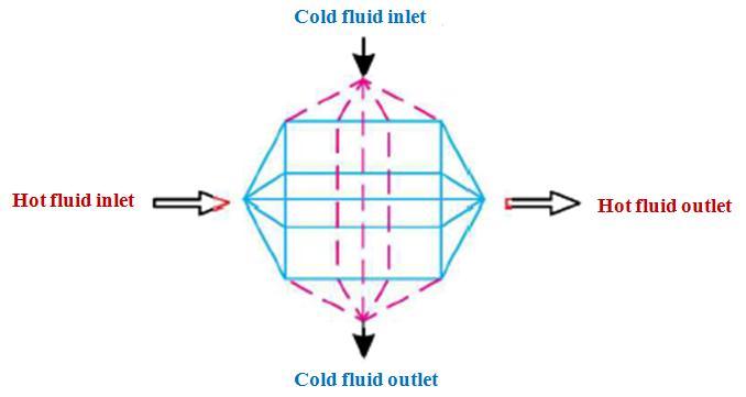
Cross flow plate fin type heat exchanger required for experimental analysis of heat transfer characteristic was constructedbyfabricationusingAluminium asitsmaterial. The heat exchanger was made of two plates, a strip of corrugatedsheetandaflatplatewhichwerefoldedonboth sides, so as to provide an enclosure to the corrugations. Corrugationswerejoinedtotheflatplatesbywelding.Flat plates acts as primary and the corrugations as secondary heattransfersurface.Theinletheaderjoinstheinletfaceof the heat exchanger core to the inlet supply pipe and the outletheaderjoinstheoutletfaceof theheatexchangercore tothereturnpipeofrespectivefluidstreams.Theschematic diagramoftheheatexchangerisshowninfigure1.
© 2022, IRJET | Impact Factor value: 7.529 | ISO 9001:2008 Certified Journal | Page2654
Research Journal of Engineering and Technology (IRJET)
Volume: 09 Issue: 04 | Apr 2022 www.irjet.net
Fig 1:Schematicdiagramofcrossflowplatefintypeheat exchanger
Thisstudyconsideredanon Newtonianfluidascoldfluidfor conductingtheexperimentincrossflowplatefintypeheat exchanger. The base fluid that used in this experimental studies was Carboxyl Methyl Cellulose CMC (C8H15NaO8) which is a non Newtonian fluid having better exchanger effectiveness
Experimentalanalysisofcrossflowplatefinheatexchanger wasconductedusingCarboxyMethylCellulose(CMC)ascold fluidfordifferentflowratesandconcentrationsasfollows:
Initiallytheboilerwasfilledwithsoftwaterandtheelectric heater was switched on to produce steam at required quantityandtemperature.
TherequiredcompositionofCMCsolutionwaspreparedina storage vessel at room temperature and atmospheric pressure.
Inletvalveonthecoldfluidstreamcircuitwasopenedand Water CMC solution at a concentration 0.01% on volume basiswasallowedtopassthroughtheheatexchangerusinga centrifugalpump.
After ensuring enough quantity of steam at required temperaturethatwasgeneratedintheboiler,theinletvalve onthehotfluidstreamcircuitwasopenedandthesteamwas allowedtopassthroughtheheatexchanger.
Afterasteadystatehasbeenreached,theflowrate,inletand outlettemperatureofbothcoldandhotfluidswerenotedand recorded.
The experiment was repeated for same concentration (0.01%) but fordifferent flow rates of coldfluid. Inlet and outlettemperatureofbothcoldandhotfluidswerenotedand recordedforeachflowrate.
Theexperimentswererepeatedfordifferentflowratesand concentrations(0,05%and0.1%)ofWater CMCsolutions. Thedataobtainedfromexperimentalstudieswereanalyzed usingMATLABsoftware.
2022, IRJET
e ISSN: 2395 0056
p ISSN: 2395 0072
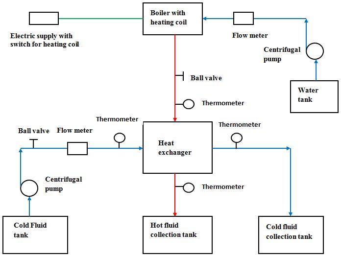
Theschematicdiagramforexperimentalsetupisshownin figure2.
Fig 2:Schematicdiagramforexperimentalsetup
Thefollowingdatacollectedduringexperimentalanalysisfor differentflowratesandconcentrationsofWater CMCsystem wererecorded:
Temperatureofcoldfluidbeforeandaftertheheat exchangert1 andt2 respectively.
Temperatureofhotfluidbeforeandaftertheheat exchangerT1 andT2 respectively.
Followingheatexchangerparametersweredeterminedusing thecollecteddata,fordifferentflowratesandconcentrations ofWater CMCsystem.:
Reynoldsnumberforbothcoldandhotfluids
Individualheattransfercoefficientforbothcoldand hotfluids
Fineffectivenessforbothcoldandhotfluids
Surfaceeffectivenessforbothcoldandhotfluids
Overallheattransfercoefficient
Heatexchangereffectiveness
Capacityratio
NumberofTransferUnits
Thedataobtainedfromexperimentalanalysisandtheheat exchangerparameterscalculatedfordifferentflowratesand concentrationsofWater CMCsystemaretabulatedintable1, 2and3 asshownbelow.
Impact Factor value: 7.529 | ISO 9001:2008 Certified Journal | Page2655
30 48.5 4.28 121 90.5 14.156 9.999 8.433 4.571 0.388 0.484 99.87 99.89 99.90 99.92 32.59
30 47.5 5.67 121 89 13.977 9.733 11.185 5.199 0.517 0.413 99.87 99.85 99.91 99.89 29.20
30 47.5 6.24 121 87.5 13.803 9.504 12.304 5.356 0.569 0.386 99.87 99.84 99.91 99.88 27.87
30 47 7.06 121 88 13.861 8.893 13.945 5.423 0.646 0.344 99.88 99.81 99.91 99.87 25.61
30 46.5 7.32 121 87 13.747 8.910 14.465 5.505 0.672 0.336 99.88 99.81 99.91 99.86 25.15
30 45 7.81 121 86.5 13.690 8.751 15.458 5.580 0.724 0.316 99.88 99.79 99.92 99.85 24.02
30 43 8.26 121 85 13.524 8.772 16.393 5.705 0.775 0.302 99.88 99.78 99.92 99.84 23.18
Fin Effective ness
Fluid Cold Fluid Hot Fluid Cold Fluid
Surface Effective ness Excha nger Effect ivene ss
NTU
30 48 4.27 121 90 14.052 10.219 8.411 4.610 0.388 0.488 99.86 99.89 99.90 99.92 32.78
30
5.65
30 46.5 6.20
30
30
7.02
7.25
30 44.5 7.78
30
8.31
13.977 9.733 11.156 5.193 0.517 0.412 99.87 99.85 99.91 99.89 29.18
88.5 13.919 9.488 12.240 5.339 0.569 0.385 99.87 99.84 99.91 99.88 27.80
13.861 9.272 13.873 5.550 0.646 0.352 99.88 99.81 99.91 99.87 26.05
13.804 9.080 14.353 5.554 0.672 0.339 99.88 99.81 99.91 99.86 25.31
13.634 8.922 15.418 5.643 0.724 0.320 99.88 99.79 99.91 99.85 24.23
85.5 13.579 8.929 16.477 5.782 0.775 0.306 99.88 99.78 99.91 99.84 23.41
30 48.5 4.28 121 88 13.861 10.790 8.433 4.730 0.388 0.500 99.86 99.89 99.90 99.92 33.35
30 48 5.69 121 87 13.747 10.399 11.215 5.390 0.517 0.428 99.86 99.85 99.90 99.89 29.96
30 47.5 6.52 121 86.5 13.690 10.066 12.863 5.640 0.594 0.389 99.87 99.83 99.90 99.88 28.01
30 47 7.06 121 86 13.634 9.781 13.945 5.741 0.646 0.364 99.87 99.81 99.91 99.87 26.71
30 46.5 7.60 121 85.5 13.579 9.535 15.022 5.824 0.698 0.342 99.87 99.80 99.91 99.86 25.50
30 45 8.09 121 85 13.524 9.318 16.010 5.881 0.749 0.322 99.88 99.79 99.91 99.85 24.34
30 44.5 8.34 121 84.5 13.469 9.124 16.519 5.868 0.775 0.310 99.88 99.78 99.91 99.84 23.68
Based on the results obtained from the analysis of heat transfer characteristics in cross flow plate fin type heat exchanger,forWater CMCatdifferentcompositions,graphs are plotted for relevant heat exchanger parameters. The results are graphically represented for individual heat transfer coefficients, overall heat transfer coefficients, fin temperatureeffectiveness,surfacetemperatureeffectiveness and heat exchanger effectiveness with respect to the Reynoldsnumberofhotandcoldfluids.
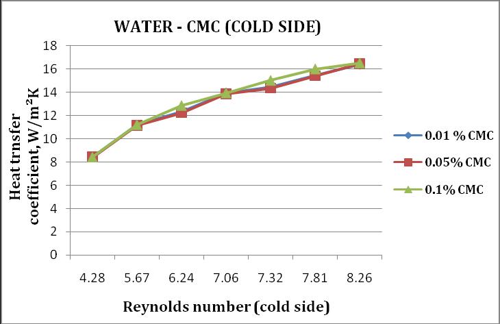
Charts1and2shownbelowarethegraphicalrepresentation between the Reynolds number and the individual heat transfer coefficient (hot and cold side) for different compositionsofCMCtoanalyzethechangesthathavebeen occurredduetothevariationinflowrateandcompositionof non Newtonianfluid.
Chart 1:HeattransfercoefficientVsReynoldsnumber (hotside)forWater CMCsystem
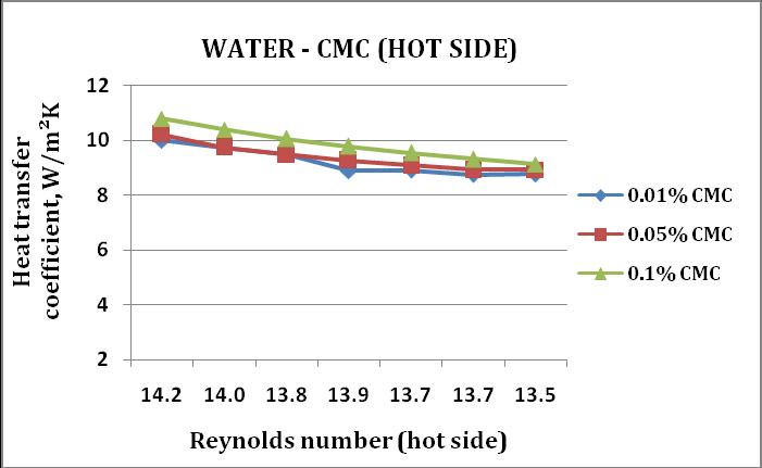
Chart 2:HeattransfercoefficientVsReynoldsnumber (coldside)forWater CMCsystem
Research Journal of Engineering and Technology (IRJET)
Volume: 09 Issue: 04 | Apr 2022 www.irjet.net
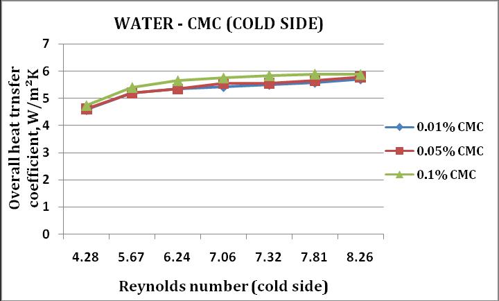
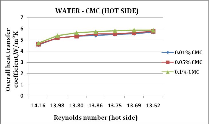
Charts3and4shownbelowarethegraphicalrepresentation betweentheReynoldsnumber(hotandcoldside)andthe overallheattransfercoefficientfordifferentcompositionsof CMCtoanalyzethe changesthathavebeenoccurreddueto thevariationinflowrateandcompositionofnon Newtonian fluid.
Chart 3:OverallheattransfercoefficientVsReynolds number(hotside)forWater CMCsystem
Chart 4:OverallheattransfercoefficientVsReynolds number(coldside)forWater CMCsystem
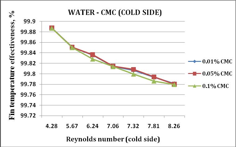
Charts5and6shownbelowarethegraphicalrepresentation between the Reynolds number and fin temperature effectiveness(hotandcoldside) fordifferentcompositions ofCMCtoanalyzethechangesthathavebeenoccurreddueto thevariationinflowrateandcompositionofnon Newtonian fluid.
e ISSN: 2395 0056
ISSN: 2395 0072
2022,
Factor value:
Chart -5:FineffectivenessVsReynoldsnumber(hotside) forWater CMCsystem
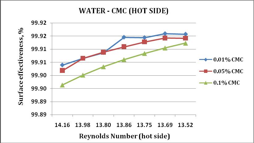
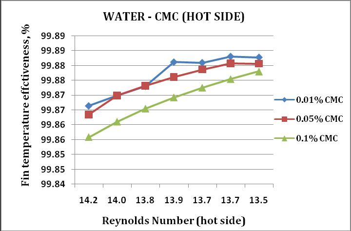
Chart 6:FineffectivenessVsReynoldsnumber(cold side)forWater CMCsystem
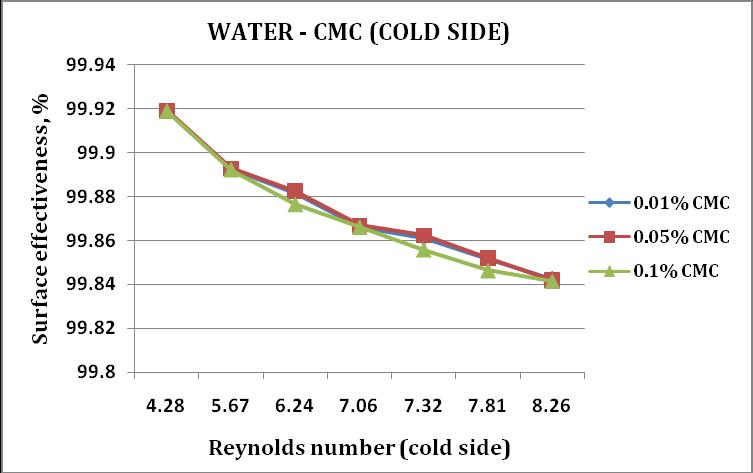
Charts7and8shownbelowarethegraphicalrepresentation betweentheReynoldsnumberandthesurfaceeffectiveness (hot and cold side) for different compositions of CMC to analyze the changes that have been occurred due to the variation in flow rate and composition of non Newtonian fluid.
Chart 7:SurfaceeffectivenessVsReynoldsnumber(hot side)forWater CMCsystem
| ISO 9001:2008
|
2658
09
Chart 8:SurfaceeffectivenessVsReynoldsnumber(cold side)forWater CMCsystem
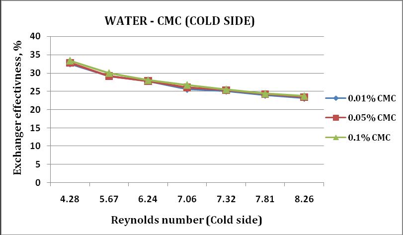
Charts 9 and 10 shown below are the graphical representationbetweentheReynoldsnumber(hotandcold side) and the exchanger effectiveness for different compositionsofCMC toanalyzethechangesthathavebeen occurredduetothevariationinflowrateandcompositionof non Newtonianfluid.
Chart 9:ExchangereffectivenessVsReynoldsnumber (hotside)forWater CMCsystem
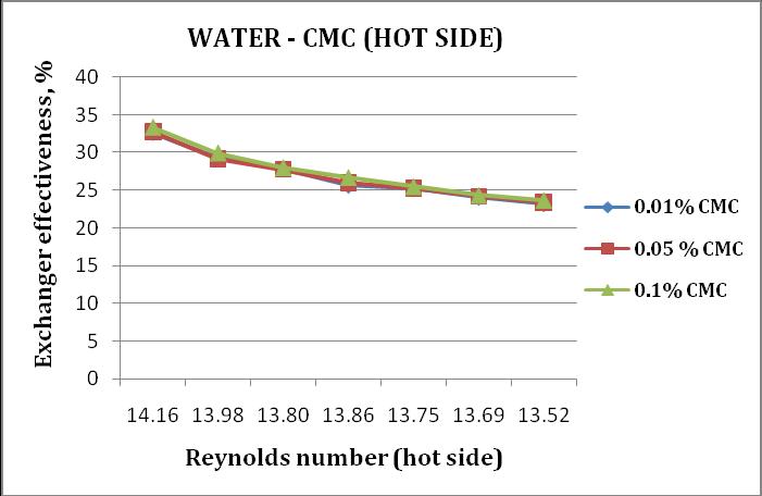
Chart 10:ExchangereffectivenessVsReynoldsnumber (coldside)forWater CMCsystem
ISSN: 2395
ISSN:
From the results of experimental analysis conducted on cross flow plate fin type heat exchanger for various compositions(0.01%,0.05%and0.1%)ofnonNewtonian fluid (Water CMC system), the following observations are made:
The individual heat transfer coefficient increases with the increaseinReynoldsnumberfordifferentcompositionsof Water CMCsystem(hotside).
The individual heat transfer coefficient increases with the increase in Reynolds number for different composition of Water CMCsystem(coldside).
The overall heat transfer coefficient decreases with the increaseinReynoldsnumberfordifferentcompositionsof Water CMCsystem(hotside).
The overall heat transfer coefficient increases with the increaseinReynoldsnumberfordifferentcompositionsof Water CMCsystem(coldside).
ThefineffectivenessdecreaseswiththeincreaseinReynolds number for different compositions of Water CMC system (hotside).
ThefineffectivenessdecreaseswiththeincreaseinReynolds number for different compositions of Water CMC system (coldside).
The surface effectiveness decreases with the increase in ReynoldsnumberfordifferentcompositionsofWater CMC system(hotside).
The surface effectiveness decreases with the increase in ReynoldsnumberfordifferentcompositionsofWater CMC system(coldside).
Theexchangereffectivenessincreaseswiththeincreasein ReynoldsnumberforWater CMCsystem(hotside).
Theexchangereffectivenessdecreaseswiththeincreasein ReynoldsnumberforWater CMCsystem(coldside).
Onthebasisoftheexperimentsconductedoncrossflowplate fintypeheatexchangerwithnon Newtonianfluid(Carboxy MethylCellulose)ascoldfluid,the effectofvariationinthe flow rate and composition of non Newtonian fluid on different heat exchanger parameters such as Reynolds number, individual heat transfer coefficient, overall heat transfer coefficient, fin effectiveness, surface effectiveness andheatexchangereffectivenesshavebeenanalyzed.
9001:2008
International Research Journal of Engineering and Technology (IRJET)
Volume: 09 Issue: 04 | Apr 2022 www.irjet.net
From the analysis of heat transfer characteristics of cross flow plate fin type heat exchanger the following main conclusionshavebeenarrived:
Theheatexchangereffectiveness increaseswiththe increaseinconcentrationofnon Newtonianfluid.
The individual heat transfer coefficient increases withtheincreaseinconcentrationofnon Newtonian fluid.
Theoverallheattransfercoefficient increaseswith the increase in concentration of non Newtonian fluid.
[1] K.Sukanya,M.LaxmiDeepak Bhatlu,NeethuJayan,K. Saranya andS. Karthikeyan, "Effectof non Newtonian fluidsontheperformanceofplatetypeheatexchanger" Journalofcriticalreviews,Vol7,issue7,2020.
[2] Seyed shahab Mozafarie and Kourosh Javaherdeh, "Numericaldesignandheattransferanalysisofanon Newtonian fluid flow for annulus with helical fins," Engineering Science and Tecnology International journal,22,2019,1107 1115.
[3] KaruppannanMuthamizhiandPonnusamyKalaichelvi, "Development of Nusselt number correlation using dimensional analysis for plate heat exchanger with a Carboxymethylcellulosesolution,"2015.
[4] ManojB.KumbhareandS. D.Dawande,"Performance Evaluation of Plate Heat Exchanger in Laminar and Turbulent flow conditions," International Journal of ChemicalScienceandApplicationsvol4,issue1,2013. 77 83.
[5] S. Nadeem, Rashid Mehmood and Noreen Sher Akbar, "Non orthogonal stagnation point flowof a nanonon Newtonianfluidtowardsastretchingsurfacewithheat transfer,"InternationalJournal HeatandMassTransfer, Vol57,(2013),Pages679 689.
[6] Salam K. Al Dawery, Ayham M.Alrahawi, Kalid M. Al Zobai "Dynamic modeling and control of plate heat exchanger," International Journal of heat and mass transferVol55,(2012),6873 6880.
[7] M. Thirumarimurugan, T. Kannadasan and S. Gopalakrishnan,"Performance analysis of cross flow finheat exchanger for Immiscible system using ANN," International journal of chemical and environmental engineering,2010,Vol1,No.1.
[8] M.ThirumarimuruganandT.Kannadasan."Simulation studies on plate type heat exchanger using ANN,"
e ISSN: 2395 0056
p ISSN: 2395 0072
InternationaljournalofChemTechReserch,Vol1,No.2, pp349 354,2009.
[9] A.A. Lambert, S. Cuevas, J.A. del Río and M. López de Haro,"Heattransferenhancementinoscillatoryflowsof Newtonianandviscoelasticfluids"2009,International JournalofHeatandMassTransfer,Volume52, (2009) 5472 5478.
[10] Isabel M.Afonso,PauloCruz,JoaoM.Maia and Luis F. Melo, "Simplified numerical simulation to obtain heat transfercorrelationsforstirredyoghurtinaplateheat exchanger"ScienceDirect,86(2008)296 303.
[11] JorgeA.W.GutandJoseM.Pinto,"Modelingofplateheat exchangers with generalized configurations," International journal of Heat and Mass Transfer, 46 (2003)2571 2585.
[12] YiminXuanandQiangLi,"Heattransferenhancementof nanofluids,"InternationaljournalofHeatandFluidflow, 21(2000)58 64.
© 2022, IRJET | Impact Factor value: 7.529 | ISO 9001:2008 Certified Journal | Page2660