
International Research Journal of Engineering and Technology (IRJET)

Volume: 09 Issue: 02 | Feb 2022 www.irjet.net
e ISSN: 2395 0056
p ISSN: 2395 0072
CONCRETE ENCASED CFST BEAM COLUMN JOINTS: A REVIEW
Ashina Anna Ronni1 , Jinta John2
1Student, St. Joseph’s College of Engineering and Technology, Palai
2Assistant Profosser, St. Joseph’s College of Engineering and Technology, Palai
***
Abstract - Beam column joints are the most seismically affected element in a framed structure, hence seismic performance of joint is of great importance for overall structural safety. In order to make appropriate design decisions for joints, it is necessary to know how joints behave.
Concrete encased concrete filled steel tubular (CFST) beam column joints consist of CFST inside and reinforced concrete outside. Several investigations have been conducted on joints with steel beams and RC columns and with steel beams and CFST columns. This paper reviews the present state of knowledgeofpropertiesandperformanceofconcrete encased CFST beam column joints.
Key Words: Beam column joints, CFST, seismic performance.
1. INTRODUCTION
Earthquakes are violent tremors in the earth's crust that generate shock waves in all directions from its point of originwhichiscausedbyasuddenreleaseofenergyinthe earth'scrustthatcausesseismicwaves.Theintersectionsof beams and columns at reinforced concrete structures are calledbeam columnjoints.Beam columnjointsarethemost seismically affected element in a framed structure, hence seismic performance of joint is of great importance for overallstructuralsafety.Theconnectionbetweenbeamand columninaframestructureismostlikelytosustaindamage duringaseismicdisaster.Inordertomakenecessarydesign decisionsforjoints,youneedtoknowhowjointsbehave.
Acompositememberisastructuralmembermadeupoftwo ormorematerialshavingdissimilarproperties [6]Asthey are made of multiple materials, they exhibit properties of both and have superior properties to the individual ones. Oneofthemostpopularlyusedcompositemembersinthe structuralengineeringindustryissteel concretecomposite. Asweallknowconcreteisgoodintakingcompressiveload and weak in taking tensile load. Also, steel is strong in tension loading. By combining both, it utilizes concrete’s compressivestrengthandsteel’sresistancetotensionand makingitmoreefficientinconstruction.Concrete filledsteel tubularstructuresareoneamongthesetypesofconcrete steelcomposite.
Concrete filled steel tubular (CFST) structures have great structural benefits, including increased strength and resistance to fire attack, high ductility and energy
2022,
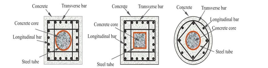
absorption. In some recent buildings, concrete encased steel tubecolumns(CFST)havebeenusedtoconnectwith reinforced concrete (RC) or steel beams. The concrete encasedconcrete filledsteel tubular(CFST)beam column jointismadeupofcoreCFSTandreinforcedconcrete(RC) outside. Asthecompositecolumnismorefire resistantand structurallydurablethanatypicalCFSToneduetotheouter RC part. Fig 1 shows typical cross section of concrete encased CFST columns. Concrete encased CFST beam columnjointsarestronger,moreductile,andcancarrymore weight than ordinary RC beam column joints due to the performance of their embedded steel tube. Moreover, the compositejointsdemonstratedfavourableseismicbehaviour and could be used in earthquake prone areas. Concrete encasedconcrete filledsteel tubular(CFST)beam column jointsconsistofCFSTinsideandreinforcedconcreteoutside. This method has certain advantages over conventional reinforcedconcrete(RC)columns,suchashigherductility duetothecontributionoftheCFST,andfasterconstruction speedbecausetheCFSTcanbeconstructedfirsttocarrythe entire construction load by itself and concrete and reinforcing bars for the outer walls can be poured or installedlater.
Fig 1:Commonlyusedcrosssectionsofconcrete encased CFSTcolumns.
2. COMPONENT BEHAVIOUR OF CFST
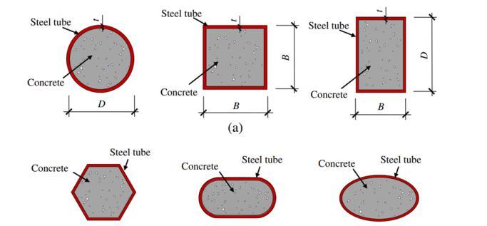
Thewidespreadapplicationofconcrete filledsteeltubes inengineeringhasledtolarge diametersteeltubecolumns beingusedinthegroundfloorsofhigh riseandsuperhigh risebuildings.Bydecreasingthecross sectionaldimensions oftheuppercolumnsasthenumberoffloorsincreases,the deadweightofthestructurewillbereducedandengineering costswillbesaved.Thecolumnconnectionswherethecross sectionalsizeschangebecomethecrucialareathataffectsthe seismicperformanceofthewholestructure.Typicalsections ofsteelusedforCFSTforfillingconcretearecircularhollow section(CHS),asquarehollowsection(SHS)orarectangular hollowsection(RHS).Itisfoundthatcircularcrosssections providethestrongestlockeduptothecoreconcrete,whereas
Factor value: 7.529 | ISO 9001:2008
Engineering and Technology (IRJET)
Volume: 09 Issue: 02 | Feb 2022 www.irjet.net
squareorrectangularcrosssectionsaremorelikelytocause local buckling. In the meantime, concrete filled steel tubes withSHSandRHSarestillincreasinglyusedinconstruction duetotheireaseofbeam to columnconnectiondesign,high cross sectionalbendingstiffness,andaestheticvalue.Theuse ofpolygons,ellipticalandrounded endedrectangularshapes foraestheticpurposesisalsobecomingcommonnow a days. Fig2showstypicalconcrete filledsteeltubularcrosssection.
Fig 2:Typicalconcrete filledsteeltubularcrosssections.
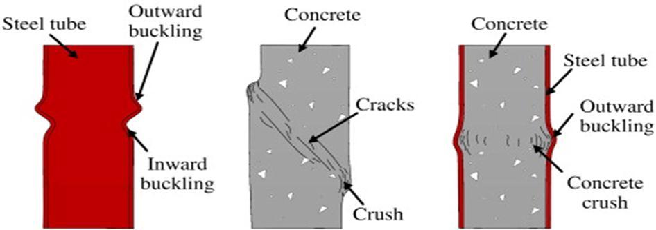
Itisknownthatconcreteisgoodintakingcompressive loadandweekintakingtensileload.Despitestructuralsteel's high tensile strength, its shape may buckle locally under compression.CFSTisdesignedinawaythatmostimportant characteristics of both concrete and steel can be taken advantageonthestructure Theconcreteandthesteeltube sustain the axial load coming to the structure together. Concreteconfinedinsteeltube,andtheconcretecorehelps to relievelocal bucklingof the steel tube. Fig3showsthe schematicfailuremodesofhollowsteeltube,concreteand CFST columns. The steel tube shows both inward and outwardbuckling,whiletheconcretecolumnexhibitsshear failure.Onlytheoutwardbucklingoftheconcrete filledsteel tubecanbeobserved,andtheinnerconcretefailsinamore ductilemanner.
Fig 3: Schematic failure modes of hollow steel tube, concreteandCFSTcolumns.
Apart from conventional CFST other members coming underthisCFSTfamilyareconcrete filleddoubleskinsteel tubes, concrete encased concrete filled steel tubes and reinforcedandstiffenedconcrete filledsteeltubes.
e ISSN: 2395 0056
p ISSN: 2395 0072
3. CONNECTIONS CONSIDERED FOR JOINTS
At the time of a seismic disaster damages usually concentrates around the beam column connection. The combination loading of shear force and bending moment tendtoleadtothedamageoftheconnectionbetweenbeam andcolumnandfurthertothecollapseofstructure.Hence, seismicperformanceofbeam columnconnectionisacritical factoraffectingthelifeofthestructure.Differentconnections consideredforjointsandtheirbehaviourwerealsostudied byauthorsandtheyarefollows:
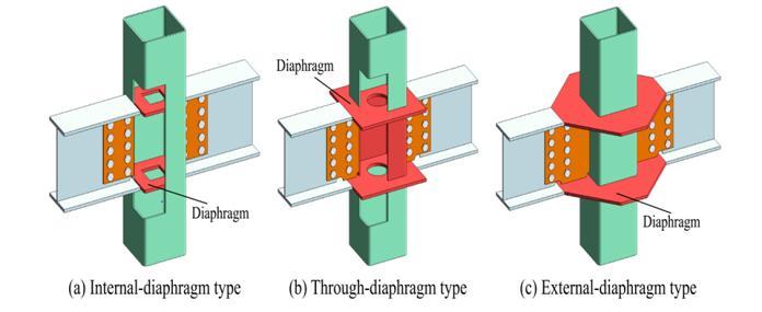
Beam columnconnectionsaremainlydividedintointernal diaphragm, through diaphragm, and external diaphragm connections. [2] The internal diaphragm beam column connectionsweldthediaphragminsidethecolumnposition correspondingtotheflangeundermaintainingthecolumn, thethrough diaphragmbeam columnconnectionsseparate the upper and lower steel tubular columns through the diaphragms connected with the beams and the external diaphragm beam column connections connect the beams and columns through the external diaphragm. In case of through diaphragm beam column connections, the arrangement of diaphragms guarantees continuity of pressure transfer, but it is difficult to weld the inner diaphragms, and only welding can secure the through diaphragmstothecolumns.Incaseofworkabilityexternal beam columnconnectionsarehighlyworkable.
Zhang et al. [3] studied the seismic behaviour on the external diaphragm beam column connections of central columnsandsidecolumnsunderaxialcompressiveloadand cyclicload.Thecyclicsheartestsofunequal heightbeam tubecolumnconnectionswithouterannularstiffenerswere carriedoutbyMouetal.[4],andtheexperimentalresults demonstrated that the increase in outer annular stiffener sizeimprovedthehystereticbehaviouroftheconnections.A studybyBaietal.[5]comparedtheseismicperformanceof steelbeam columnsconnectedwithouterannularstiffeners under unidirectional and bidirectional cyclic loads and proposed the calculation of strength formula for ring stiffeners.Whencomparedwiththeothertwoconnections, external diaphragmbeam columnconnectionshavebetter structuralperformance,includinghigherbearingcapacity, betterplasticdeformation,andmoreefficientstresstransfer.
9001:2008
Fig 4:Thetypicalbeam columnconnections.International Research Journal of Engineering and Technology (IRJET)
Volume: 09 Issue: 02 | Feb 2022 www.irjet.net
The investigations on the connection behaviour of CFST column to beamjointimplantedbysteelrebarsundercyclic loadingbyMouetal.concludedthat
Most of the bending moment and plastic deformation of the whole column to beam joint occurs at the column column connections. There was a noticeable rotational deformation at the connectionbetweentheupperandmiddlecolumns as opposed to the connection between the lower andmiddlecolumns.
Straindistributionsontheouterannularstiffeners and webs bolted to the beam indicated that their contributiontothedeformationofCFSTcolumn to beamjointswaslimited.
Itwasfoundthatintheconnectionzone,steeltubes tendedtoaxiallydeformmostlyattheconnections between the beam and the column flanges rather than at the webs of the column. Compression expansionoftheinfilledconcreteisthoughttobe responsibleforthebulgingoutwardofthecolumn flanges.
4. EXPERIMENTS
Severalscholarsconductedexperimentalinvestigationson the performance of concrete encased concrete filled steel tubular(CFST)structures.
Experimental research and numerical simulation are conductedonsquareconcrete encasedCFSTstubcolumns after ISO 834 fire exposure in order to find mechanical propertiesisdonebyKaietal.[7]temperaturedistribution andloadversusdisplacementarecalculated.Fromstudyitis concluded that compressive failure is the mode of failure noticed in the fire exposed concrete encased CFST stub column.Timeofexposureofspecimeninfireandsectional area of corehavesignificant influence onthe reduction of axial compressive strength and axial stiffness of square concrete encasedCFSTstubcolumnsaftertheexposurein fire.
5. EXPERIMENTAL PROGRAM TO FIND SEISMIC PERFORMANCE OF CONCRETE ENCASED CFST BEAM- COLUMN JOINTS.
e ISSN: 2395 0056
p ISSN: 2395 0072
Fortheexperimentsfollowingdataareused:
5. 1 Material properties
Amildsteelplatewascutintobeamwebsandflanges,then welded together and straight electric weld was applied to the steel tube for the column. Table 1 lists the material propertiesofsteel.
Inthetest,twotypesofconcretewereused,a corefilling tubeisfortheinsidesteeltube,andanouterRCandslabare for the outside steel tube. The concrete placement was performed in two steps. At first, the steel tube of all specimenswasfilledwithcoreconcrete.Afterthat,theouter concretealongwiththeslabconcretewereplacedtogether forall specimens. For eachtypeofconcrete specimen,the compressive strength of concrete cube (fcu) was obtained and the average strength value was calculated only if the strengtherrorbetweentestedcubeswaslessthan15%. The obtained concrete strength as well as the mixtures are presentedinTable2.
Table 1: Materialpropertiesofsteel.
Components t or d mm
fy N/mm2 fu N/mm2
Es N/mm2
�� %
Beamflange 10 386 472 2.14x10⁵ 36.7
Beamweb 8 395 495 2.05x10⁵ 25.4
Tube 6 371 535 1.97x10⁵ 23
Rebar 8 343 516 1.91x10⁵ 23.1 10 383 547 1.99x10⁵ 19.8 14 396 523 2.08x10⁵ 24.1 18 384 529 2.05x10⁵ 25.8
Table 2:Mixturesandpropertiesofconcrete.
Type Coreconcrete Outerconcrete Cement(kg/m3) 428 284 Coarse aggregate (kg/m3) 870 870
Fine aggregate (kg/m3) 783 783
In the study conducted by Wei Li et al. [1] Experimental investigation was carried out for joints made up of steel beamsandconcrete encasedCFSTcolumn.Inhisexperiment constantaxialloadingisappliedontopofthecolumn,and thereversecyclicloadingwasappliedatthebeamends.The failure patterns, the hysteretic relations, the deformation andthestraindistributionswererecordedandanalyzed.
2022,
IRJET | Impact Water (kg/m3) 186 207
© Flyash(kg/m3) 143 129
Factor value: 7.529 | ISO 9001:2008
Certified Journal | Page2467 Water Reducer (kg/m3) 8.56 5.13 fcu (N/mm2) 69.7 65.7
ISSN: 2395
ISSN: 2395
5. 2 Loading apparatus
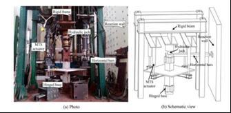
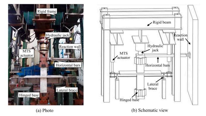
Twocolumnsweresimplysupported,andbothbeamends were connected to independently worked MTS actuators. Thetestsetupsforplanarjointsand3 Djointsareshownin Fig.5andFig.6,respectively.Toapplytheaxialcompressive loadtothecolumn,ahydraulicjackof5000kNwasused.In the next step, beams were subjected to reversible cyclic loads that were gradually increased keeping axial compressiveloadconstantthroughoutthetest.Duringthe forcecontrolstage,theactuatorswerecontrolledatarateof approximately 1 kN/s; during the displacement control stage, they were controlled at a rate of approximately 1 mm/s.
Theexperimentswerefinishedwhenallthreecyclesof5Δy werecompletedorthejointstrengthdroppedbelow85%of themaximumload.
5. 3 Measurements
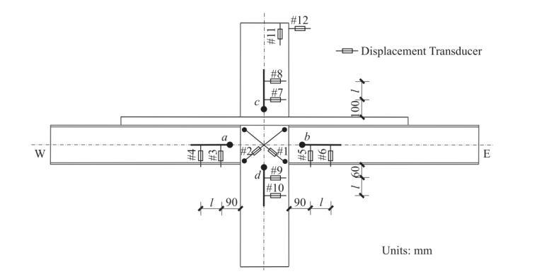
InMTSactuators,thecyclicloadsanddisplacementsatbeam ends are directly measured by transducers. In order to measure strains at different locations, numerous strain gaugeswereinstalledandarrangementoftransducersare showninFig.7.Thesetransducersareusedformeasuring jointsheardeformations,relativerotationbetweencolumn andbeametc.
5. 4 Experimental results
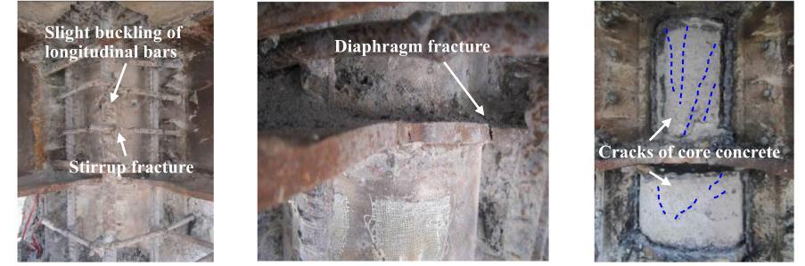
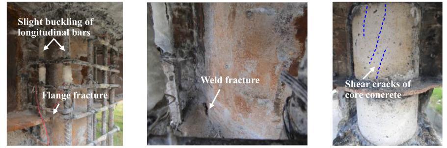
The tests were controlled well and completed smoothly. Numerousfailuresofcomponentswereobservedduringand afterthetests,includingcrushingandcrackingofconcrete, bucklingofbeamflangesandlongitudinalbars,asshownin Fig.8
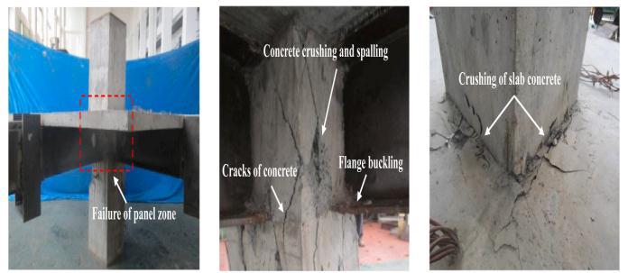
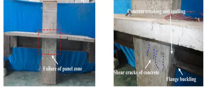 Fig 5:Testsetupforplanarjoints.
Fig 6:Testsetupfor3Djoints.
Fig 7.Arrangementofdisplacementtransducers.
Fig 8:Typicalcomponentfailures.
Fig 5:Testsetupforplanarjoints.
Fig 6:Testsetupfor3Djoints.
Fig 7.Arrangementofdisplacementtransducers.
Fig 8:Typicalcomponentfailures.
Research Journal of Engineering and Technology (IRJET)
Volume: 09 Issue: 02 | Feb 2022 www.irjet.net
Within the parameter range of this study, following conclusionsaremade:
Threetypesoffailurewereidentifiedforthetested jointspecimens:thebeambendingfailure,thepanel shearfailure,andthecolumncompression bending failure.
Asthebeam to columnstrengthratioincreased,the load carrying capacity increased, while the axial loadlevelhadlittleimpact.
Theload carryingcapacityincreasedasthebeam to columnstrengthratioincreased,whiletheaxial loadlevelhadminoreffect.[1]
6. CONCLUSIONS
Inthisreviewconcreteencasedconcretefilledsteeltubular structure,itsproperties,components,connectionbehaviour, loadcarryingcapacityetc.withapracticaltestissuccessfully studiedandanalyzed.Fromthereviewoftheliteraturesand my studies it is concluded that concrete filled CFST structures perform well under loading conditions. As the beam column strength ratio increased, little impact is shownonaxialload.Fewfailuretypesarenoticedsuchas beam bending failure, panel shear failure, compression bendingfailureetc.
Asitisacompositematerialitshowspropertiesofbothsteel andconcrete.Duetoexcellentfireresistance,loadcarrying capacity, durability etc. it becomes a better choice for constructionindustry.
REFERENCES
[1] Wei Li, Li Feng Xu and Wei Wu Qian, “Seismic performance of 3 D steel beam to concrete encased CFSTcolumnjoints:Tests”,2021.
[2] Ben Mou, Yingze Li and Qiyun Qiao, “Connection behavior of CFST column to beam joint implanted by steelrebarsundercyclicloading”,2021.
[3] ZhangD,GaoSandGongJ,“Seismicbehaviourofsteel beamtocircularCFSTcolumnassemblieswithexternal diaphragms”,2012.
[4] MouB,LiXandBaiYT,“Shearbehaviourofpanelzones in steel beam to column connections with unequal depthofouterannularstiffener”,2019.
[5] Bai Y, Wang S and Mou B, “Bi directional seismic behaviorofsteelbeam columnconnectionswithouter annularstiffener”,2021.
[6] K.B.ManikandanandC.Umarani,“Understandingson the Performance of Concrete Filled Steel Tube with DifferentKindsofConcreteInfill”,2021.
2022,
e ISSN: 2395 0056
p ISSN: 2395 0072
[7] Kai Xiang, Yan chong Pan and Guo hui Wang, “Axial compression analysis of square concrete encased concrete filled steel tubular stub columns after fire exposure”,2017.
[8] Fei YuLiao,Lin HaiHanandZhongTao,“Behaviourof compositejointswithconcreteencasedCFSTcolumns undercyclicloading:Experiments”,2014.
[9] Wei Li, Li Feng Xu and Wei Wu Qian, “Seismic performanceofconcrete encasedCFSTcolumntosteel beamjointswithdifferentconnectiondetails”,2022.
[10] Yu Feng An, Lin Hai Han and Charles Roeder, “Performance of concrete encased CFST box stub columnsunderaxialcompression”,2015.
Impact Factor value: 7.529 | ISO 9001:2008