
Volume: 09 Issue:
of Engineering and Technology (IRJET)

| Apr 2022 www.irjet.net
e ISSN: 2395 0056
p ISSN: 2395 0072
Kothamasu Akhil1 , P.Manikanta 21M.Tech, Department Of Civil Engineering, Gayatri Vidya Parishad College for Degree and P.G Courses(A), Rushikonda, Visakhapatnam, A.P, India.
2Assistant Professor, Department Of Civil Engineering, Gayatri Vidya Parishad College for Degree and P.G Courses(A), Rushikonda, Visakhapatnam, A.P, India.
***
Abstract - In the past, most structures built on hilly terrain withstood disasters and other natural disasters; however, due to changes in techniques and methods, as well as the enormous level of structures on the surface, the stability of soil, wind loads, and seismic loads should be considered; for this purpose, only a committee is formed, and Indian standards are formed, and they are revised whenever it is recommended. To achieve results, the advancement of technology/software systems is used. Many software’s, such as SAP2000, Staad Pro, Revit Structural, E tabs, Tekla, and others, are available to reduce manual calculation and time, resulting in accurate values. Now, for this project, we will use Staad Pro software to generate structural drawings of G+5 and G+10, and by applying Dead Load, Live Load, Seismic Load, and Wind Load to the structure, we will obtain Storey drift values and conduct a comparative study between the four models.
Key Words: KeyStaad Pro,Storey,Loads,Beams,Columns, yieldstrength,Compressivestrength,Deflection,Structure, moments,StoreyDrift,Shearwall,multistoreybuildingwith andwithoutshearwall,Baseshear,Seismicanalysis,lateral loading,axialload.
1. INTRODUCTION
DesignEngineerscreatedanapplicationfordesignanalysis anddesignsoftwarein1997togetaccurateresultsinless timeandtoreducetheneedformanualcalculation.Later,in 2005, Bentley Systems purchased the application from research Engineers, renamed it Staad/Staad Pro, and releaseditinternationally.
Wecaneasilyapplyloadcasesandchecktheshearfailure conditionsinthisstaadpro.Wecanestimatethemaximum heights of buildings using this application, and most constructioncompaniesarecurrentlytakingtheheightupto 30floors(Knownvalue)(inAndhraPradesh),whichgives morespaceinthefloorwisewithinlessspaceofland.
2. MAIN OBJECTIVES FOR THE STUDY
Someoftheobjectivesforthestudyareasfollows:
1) Identifytheloadcasewiththegreateststoreydrift value.
2) To determine the maximum storey drift values in which model and for which height of the building the maximumvalueisfound.
3) Whether it is in safe (or unsafe) construction condition.
4) Todeterminewhetherthedesigncanwithstandthe combinedearthquakeandwindforces.
5) Designing the structure as an under reinforced section ratherthananoverreinforcedsection.
3. RESEARCH METHODOLOGY
Inputting the job Information:
Generatingthe3Dmodelgeometry.Therearetwo methodstocreateastructureinSTAADPRO.
a) Usingthe“STAADPROEditor”
b) UsingtheGraphicalUserInterface(GUI)
WecreatedtheentirestructureusingtheGraphicalUser Interface (GUI) because it is the simplest way to create by usingnodesandbeams,andforsomeoftheloadcalculations, suchasstoreydriftvaluesandloadcases,weusedtheStaad editormethod.WeusedStaadeditorbecausethenumberof loadcaseswasgreater,andforsoftwarecalculations,weused commands such as Perform Analysis, Change, Print Storey drift,andsoon.
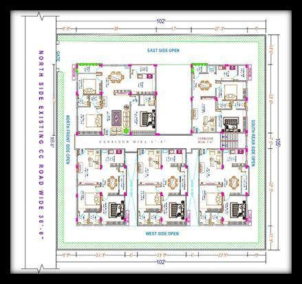
As shown in fig 1, the nodes and beams are created in STAADPro.
9001:2008
Comparative study of a multi – storied building with and without shear wall between Mid – rise and High – rise building by using STAAD.Pro
Fig -1:ReferenceofAutocaddrawingplan
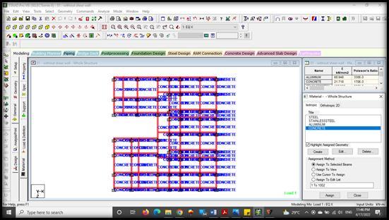
Assigning the material:
Asaftercreatingthebeamsandcolumnswewillassign materialtothemaswerequire.Ourdesignisconcretedesign hencewehaveassignedtheconcretematerialtothebeams andcolumns
Specifying member properties:
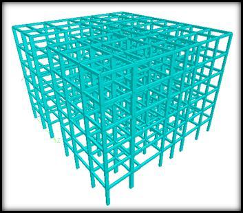
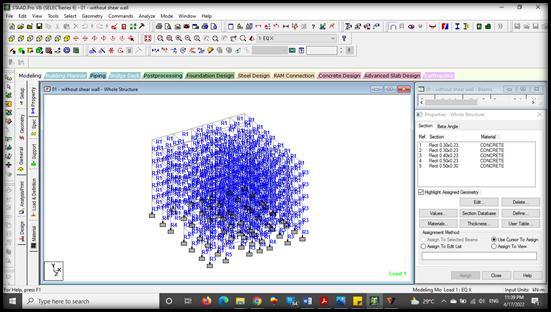
The size of the beams and columns is one of their properties(width,depthofcross section,Beta Angle).So, usingthiscommand,weenteredthevariousproperties(such as circular, rectangular, and square) and assigned these propertiestothespecifiedmembers,asshowninfig2,3.
Fig 3:3D Renderingmodel
Specifying material constants:
weassignedtheconcretematerial,wehavetheconcrete constantsbydefaultanddonotneedtousethiscommand separately.Ifweneedtochangetheconstants,wecanusethe commandshowninfig4.
Fig 4:Assigningmaterialstothemembers
Specifying Supports:
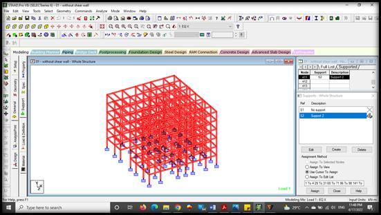
The supports are first created (as we did with fixed supports) and then assigned to all of the structure's lowermost nodes where we will design the foundation, as showninfig5.
Fig 2:Materialsafterassigningtothebeamsandcolumns Fig 5:SupportsforthecolumnatalltheendnodesResearch Journal of Engineering and Technology (IRJET)
Volume: 09 Issue: 04 | Apr 2022 www.irjet.net
Specifying Loads:
Thisisdoneinfollowingtwosteps:
a) First,allloadcasesmustbecreatedinaccordancewith Indianstandards.
b) Thentheyareassignedtotheappropriatemembersand nodes.
IS Codes considered for the Design:
(i.) IS456 2000
(ii.) IS875Part 1(DeadLoad)
(iii.) IS875Part 2(LiveLoad)
(iv.) IS875Part 3(WindLoad)
(v.) IS875Part 5(LoadCombinations)
(vi.) IS1893Part 1(EarthquakeLoad)
TheSTAADPROcangenerateanytypeofloadandassignitto astructure.Itisalsocapableofimposingadeadloadonthe structure. Before creating specific load cases, some load definitions are created in accordance with IS codes (As Seismic or wind load). Hereare some of the loads thatwe haveassigned.
Dead Load:
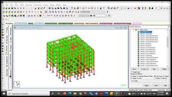
Theloadcomingonframedstructureduetoself weightof beams,columns,slabsorwalls.Thisloadwillactasuniformly distributedloadoverthesupportingbeamsasshowninfig6.
Sesimic Load:
Fig -6:DeadLoad(Selfweight)
Live Load:
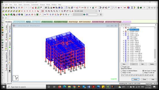
Theliveloadcomesonstructureduetoextranecessary thingsinthehouse.TherewillbedifferentLiveLoadsacting inthestructureduetodifferentusesofbuilding.Asherewe have used various types of different live loads in our structure.
Wind Load:
Wind Load is defined as the wind speed acting on the structure, and wind load values will be considered in accordancewithIScode.
2022, IRJET
e ISSN: 2395 0056
p ISSN: 2395 0072
Seismicloadingisafundamentalconceptinearthquake engineering that refers to the application of earthquake generatedagitationtoastructure.Itoccursatastructure's contact surfaces, whether with the ground, adjacent structures,orgravitywaves.
Dimensions & Loads Considered (fig 2 & fig 7):
ColumnSize 0.23mx0.23m,0.3mx0.23m, 0.4mx0.23m,0.5mx0.23m, 0.5mx0.3m,0.5mx0.4m, 0.6mx0.5m,0.7mx0.5m
BeamSize 0.23mx0.23m,0.3mx0.23m, 0.4mx0.23m,0.5mx0.3m, 0.6mx0.4m,
GradeofConcrete M30
GradeofSteel Fe 415(HYSDBars)
HeightoftheStructure G+5 18m(Mid riseBuilding) G+10 33m(High riseBuilding)
Shearwallthickness 0.15m(Mid riseBuilding) 0.5m(High riseBuilding)
Dead Load:
Selfweight 1
WallLoad 12.5Kn/m(9”Wall)(Externalwalls) 6.5Kn/m(4”Wall)(Internalwalls) 2.5Kn/m(4”Wall)(Parapetwalls)
SlabLoad 3.75Kn/m(150mmthickness)
FloorfinishLoad 1Kn/m
Live Load:
FloorLoad 2Kn/m(Residential)
Wind Load:
Pd 1509.759(@18m)
Pd 1650.31(@33m)
StructureClass B
Seismic Load:
Zone 2(MediumSoil)
Zonefactor 0.10 R 3(OMRF)
Load Combinations:
The load combinations were generated using the auto loadcombinationscommand.Wecangenerateloadsbased ontheIndiancodeandtheyareasfollows:
Impact Factor value: 7.529 | ISO 9001:2008 Certified Journal
2444
Research Journal of Engineering and Technology (IRJET)
Volume: 09 Issue: 04 | Apr 2022 www.irjet.net
(i.) 1.5(D.L+L.L)
(ii.) 1.5(D.L+EQX)
(iii.) 1.5(D.L+EQZ)
(iv.) 1.5(D.L+WindX)
(v.) 1.5(D.L+WindZ)
(vi.) 1.2(D.L+L.L+EQX)
(vii.) 1.2(D.L+L.L+EQZ)
(viii.) 1.2(D.L+L.L+WindX)
(ix.) 1.2(D.L+L.L+WindZ)
Total19LoadCombinationsaddtheseloadsbyselecting it. These combinations do not need to be assigned to individuals.Assoonasalloftheloadshavebeenassignedto thestructure,wewillproceedtothenextstep.
Fig 7:AssigningLiveLoadtothebeamsinX&Zdirection
Specifying the analysis type:
Beforeperformingtheloadanalysis,wemustspecifythe analysiscommand,whichmustbeofthelinearstatictype. Wewilladdthiscommandafterselectingstaticscheck.
Post Analysis print command:
We need to obtain member end forces and support reactions,whicharewrittenintheoutputfile.Byclickingon post analysis,adialogueboxwillopen,andbyclickingdefine command, we can add the commands we need and assign themtomemberswhowillbeanalyzed.
Run Analysis:
Thestructurewillbeanalyzedinrelationtotheloads,and this command will also indicate whether there are any warningsorerrors.ModeofPost Processing:'Inthismode, we can see results. The structure with values can have deflection,bendingmoment,shearforces,andreactionson supports.ThefiguresbelowareforDeadLoad.Wecanalso see figures underLive Loador anyothercategorythatwe want.
2022,
e ISSN: 2395 0056
p ISSN: 2395 0072
Afterperformingallstructuralanalysesonourstructure, wedesignedittodeterminethesteelusedforcolumnand beam reinforcement. We will define parameters for our design byselecting the code IS: 456 2000 for theconcrete design.
We will nowissuecommands for the design of beamsand columns after we have received all of these inputs. Once added, these are chosen and assigned to the structure's appropriatecomponents.Thestructureisthenanalyzedonce moreinpreparationforreportgeneration.
3. CONCLUSIONS
(i.) Model1hasamaximumstoreydriftvaluefortheLoad Case1.5(D.L+EQX).
(ii.) ModelNo.2,4hasamaximumstoreydriftvalueforthe LoadCase1.5(D.L+EQX)
(iii.) Model3hasamaximumstoreydriftvaluefortheLoad Case1.5(D.L EQX)
Bycomparingthevalueswecanobservethattheloadcaseof 1.5(D.L+EQX)givesthemaximumstoreydriftvalueandcan beconsideredasmainloadcaseandforMid risebuildings theshearwallisnotnecessaryandwhencomparedtothe High risebuildingtheshearwallisnecessary.
Impact Factor value: 7.529 | ISO 9001:2008
2445
Engineering and Technology (IRJET)
Volume: 09 Issue: 04 | Apr 2022 www.irjet.net
4. Comparison of Results:
e ISSN: 2395 0056
p ISSN: 2395 0072
WegetresultsfromanalyzingthevaluesinSTAADPro,inwhichwecanseetheShearforcesandBendingMomentvalues.We canalsoseethevaluesofdifferentmodelsinTables1 4(shownbelow).
Table 1: G+5withoutshearwall
Beam L/C Fx kN Fy kN Fz kN Mx kNm My kNm Mz kNm
Max Fx 435 12 1.5 (D.L + L.L) 304.526 -18.382 22.829 -0.277 -38.136 -43.762
Min Fx 592 12 1.5 (D.L + L.L) -272.102 -36.414 45.612 -0.373 -87.012 -97.636
Max Fy 600 12 1.5 (D.L + L.L) -5.203 69.53 1.742 -0.041 -1.387 53.674
Min Fy 444 12 1.5 (D.L + L.L) -1.128 -52.139 1.625 -0.492 -1.579 -46.057
Max Fz 320 12 1.5 (D.L + L.L) -127.268 -23.989 62 -0.223 -93.811 -46.907
Min Fz 384 12 1.5 (D.L + L.L) -5.2 -1.47 -13.972 -3.502 13.726 -4.222
Max Mx 328 12 1.5 (D.L + L.L) -2.373 34.427 1.628 17.445 0.262 41.3
Min Mx 192 12 1.5 (D.L + L.L) -0.609 11.569 -0.146 -15.49 0.367 43.782
Max My 320 12 1.5 (D.L + L.L) -127.268 -23.989 62 -0.223 92.188 25.059
Table 2: G+5withshearwall
Beam L/C Fx kN Fy kN Fz kN Mx kNm My kNm Mz kNm
Max Fx 43 12 1.5 (D.L + L.L) 475.101 -9.398 3.184 1.087 -7.073 -26.376
Min Fx 304 12 1.5 (D.L + L.L) -328.468 -15.124 3.88 0.435 -6.992 -35.559
Max Fy 68 12 1.5 (D.L + L.L) 78.376 41.736 -19.972 1.344 26.783 61.995
Min Fy 147 12 1.5 (D.L + L.L) 16.72 -51.875 5.36 -0.13 -10.895 -149.257
Max Fz 427 12 1.5 (D.L + L.L) 4.67 1.148 36.908 -0.298 -48.576 0.718
Min Fz 527 12 1.5 (D.L + L.L) 19.807 -0.469 -22.229 -0.522 39.483 -0.948
Max Mx 54 12 1.5 (D.L + L.L) -251.323 -8.332 -2.782 3.047 2.116 -14.005
Min Mx 339 12 1.5 (D.L + L.L) -68.969 -1.226 -8.379 -5.099 8.169 -5.273
Max My 427 12 1.5 (D.L + L.L) 4.67 1.148 36.908 -0.298 48.492 -2.302
Table 3: G+10withoutshearwall Beam L/C Fx kN Fy kN Fz kN Mx kNm My kNm Mz kNm
Max Fx 556 12 1.5 (D.L + L.L) 3026.637 5.835 -1.019 0.272 -8.716 7.866
Min Fx 704 12 1.5 (D.L + L.L) -32.564 25.974 -3.145 -1.188 5.06 18.872
Max Fy 594 12 1.5 (D.L + L.L) -1.884 146.298 1.097 -80.004 -1.456 269.116
Min Fy 776 12 1.5 (D.L + L.L) -8.609 -143.584 6.459 15.87 7.006 209.618
Max Fz 586 12 1.5 (D.L + L.L) 2585.948 49.911 72.295 -0.226 -111.886 75.185
Min Fz 696 12 1.5 (D.L + L.L) 142.109 41.177 -23.289 0.458 25.306 58.647
Max Mx 720 12 1.5 (D.L + L.L) -26.334 -52.536 -4.156 17.073 5.966 -53.47
Min Mx 692 12 1.5 (D.L + L.L) 7.388 140.412 -2.609 -85.61 2.261 249.564
Max My 586 12 1.5 (D.L + L.L) 2564.743 49.911 72.295 -0.226 105 -74.549
9001:2008
International Research Journal of Engineering and Technology (IRJET)
Volume: 09 Issue: 04 | Apr 2022 www.irjet.net
Table 4: G+5withshearwall
e ISSN: 2395 0056
p ISSN: 2395 0072
Beam L/C Fx kN Fy kN Fz kN Mx kNm My kNm Mz kNm
Max Fx 630 12 1.5 (D.L + L.L) 2657.256 -8.385 7.646 -0.437 -10.133 -12.028
Min Fx 547 12 1.5 (D.L + L.L) -1083.91 11.442 -11.044 1.019 -16.032 -26.328
Max Fy 160 12 1.5 (D.L + L.L) 15.966 129.08 1.027 -0.042 -0.594 113.536
Min Fy 414 12 1.5 (D.L + L.L) -3.069 -155.686 -0.515 -3.82 0.719 125.04
Max Fz 260 12 1.5 (D.L + L.L) -2.183 16.175 37.953 0.888 -49.257 22.908
Min Fz 1604 12 1.5 (D.L + L.L) -533.817 10.637 -16.071 0.103 22.549 12.709
Max Mx 807 12 1.5 (D.L + L.L) -27.756 -52.509 -1.079 8.722 1.554 -61.191
Min Mx 658 12 1.5 (D.L + L.L) -1.441 82.411 0.383 -8.649 -0.606 86.589
Max My 260 12 1.5 (D.L + L.L) -53.763 16.175 37.953 0.888 64.603 -25.617
WecanalsotheabovevaluesinthegraphicalrepresentationasrepresentedinbelowChart1.
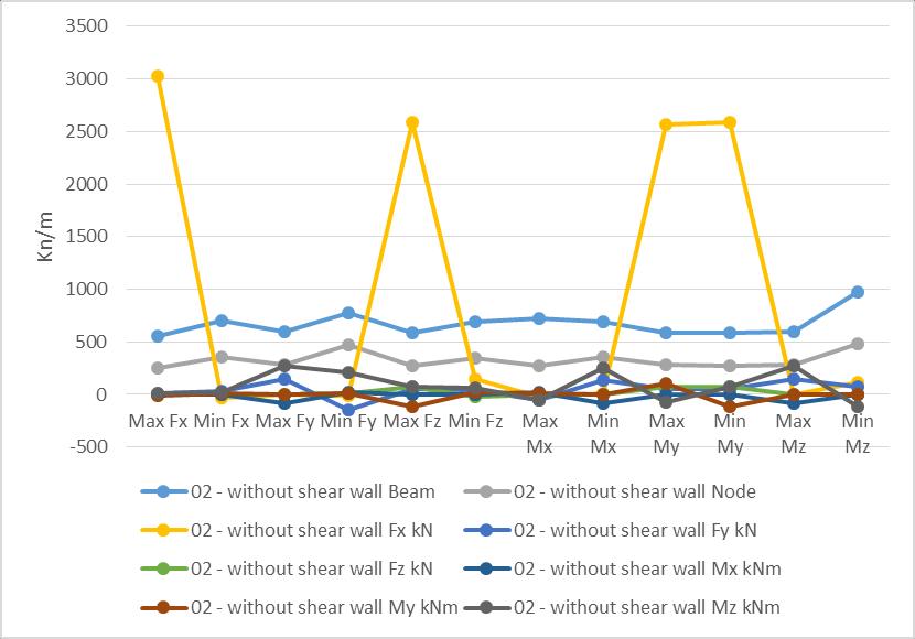
Chart 1:GraphicalrepresentationofShearforcesandBendingMomentvalues
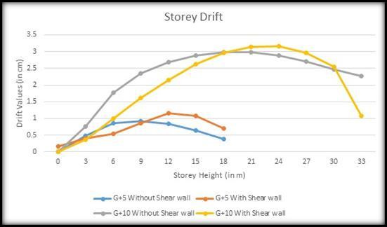
formid risestructuresThestoreydriftvalueofthestructurewithshearwallprovidedbuildingseemstobegreaterthanthe storeydriftvalueofthestructurewithoutshearwall,andthestoreydriftvalueofthestructurewithoutshearwallisgreater thanthestructurewithshearwallforhighrisebuildings.WecanalsoseethestoreydriftvaluesandcomparisoninChart2
Factor value: 7.529 | ISO 9001:2008
2447
Research Journal of Engineering and Technology (IRJET)
Volume: 09 Issue: 04 | Apr 2022 www.irjet.net
Chart 2:Graphforcomparingthestoreydriftvalues betweenMid riseandHigh risebuildingwithandwithout shearwall
REFERENCES
[1] PankajYadav,andRishabhJoshi,“EffectofHeightand PositionofShearWallonG+5Multi StoreyBuildingfor Zone III”, International Journal of Recent Technology and Engineering (IJRTE), Vol. 8 Issue 3, September 2019,pp.5452 5456.

[2] P.Kalpana,R.D.Prasad,andB.KranthiKumar,“Analysis of Building with and without Shear Wall at Various Heights and Variation of Zone III and Zone V”, International Journal of Engineering Research and Application,Vol.6,Issue12,(Part 2)December2016, pp.05 11.
[3] MaikeshChouhan,andRaviKumarMakode,“Dynamic AnalysisofMulti StoreyedFrame ShearWallBuilding ConsideringSSI”,InternnationalJournalofEngineering ResearchandApplications(IJERA),Vol.6,Issue8,(Part 1)August2016,pp.31 35.
[4] V.ABHINAV, Dr. S.SREENATHA REDDY, M.VASUDEVA NAIDU,andProf.S.MADANMOHAN“SeismicAnalysis of Multi Story RC Building with Shear Wall Using STAAD PRO”, INTERNATIONAL JOURNAL OF INNOVATIVE TECHNOLOGY AND RESEARCH (IJITR), Volume No.4, Issue No.5, August September 2016, pp.3776 3779.
[5] VarshaR.Harne,“ComparativeStudyofStrengthofRC Shear Wall at Different Location on Multi storied Residential Building”, International Journal of Civil EngineeringResearch,Vol.5,No.4(2014),pp.391 400.
[6] AshokThakur,ArvinderSingh,“ComparativeAnalysis ofaMultistoriedResidentialBuildingwithandWithout ShearWallusingSTADDPro”,InternationalJournalof RecentResearchAspects,Vol.1,Issue1,June2014,pp. 54 57.
[7] Himalee Rahangdale, and S.R.Satone, “Design And AnalysisOfMultistoriedBuildingWithEffectOfShear Wall”, International Journal of Engineering Research
2022,
e ISSN: 2395 0056
p ISSN: 2395 0072
andApplications(IJERA),Vol.3,Issue3,May Jun2013, pp.223 232.
[8] S.V.Venkatesh,andH.SharadaBai,“EffectofInternal& ExternalShearWallonPerformanceofBuildingFrame Subjected to Lateral Load”, International Journal of Earth Sciences and Engineering, Vol. 04, No 06 SPL, October2011,pp.571 576.

[9] Anand,N.,Mightraj,C.,andPrinceArulraj,G.,“Seismic Behaviour of RCC Shear Wall Under Different Soil Conditions”, Indian Geotechnical Conference 2010, GEO trendz, December 16 18, 2010, IGS Mumbai Chapter&IITBombay
BIOGRAPHIES
Impact Factor value: 7.529 | ISO 9001:2008
KOTHAMASUAKHIL
M.Tech, Department Of Civil Engineering, Gayatri Vidya Parishad College for Degree and P.G Courses (A),Rushikonda,Visakhapatnam,A.P, India P.Manikanta
Assistant Professor, Department Of Civil Engineering, Gayatri Vidya Parishad College for Degree and P.G Courses (A), Rushikonda, Visakhapatnam,A.P,India