International Research Journal of Engineering and Technology (IRJET) e-ISSN:2395-0056

Volume: 09 Issue: 12 | Dec 2022 www.irjet.net p-ISSN:2395-0072
International Research Journal of Engineering and Technology (IRJET) e-ISSN:2395-0056
Volume: 09 Issue: 12 | Dec 2022 www.irjet.net p-ISSN:2395-0072
Basavalingappa1 , Basavaprabhu MS2 , Megha N Belagal3 , Venkana gouda4
12,3Assistant Professor, Department of Civil Engineering, RYMEC, Ballari
4PG Scholar, Department of Civil Engineering, RYMEC, Ballari
Abstract - The field of earthquake engineering and design has been significantly changed by the useofseismicprotection devices like dampers. Without these devices, structures are typically designed and constructed according to code, which implies significant structural damage, loss of functionality, and most likely replacement in theevent of design-levelevents. In contrast, seismicdesignthat includes earthquakeprotection devices results in the best design possible and combines best engineering practise with low cost. These tools have a demonstrated exceptional performance history during previous earthquakes, are reliable, and are economical. Most of the time, the initial cost of using them is offset, at least in part, by the lower cost of other structural components. With the aid of ETABS software, buildings have been examined in the current study under the influence of seismic loads and viscous dampers. In addition, the configurations' story displacement, story drift, and base shear at foundations were compared to the seismic parameters derived fromtheanalysis.
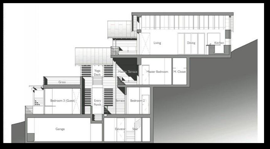
Themostabominableandfleetingwonderofnature isseismicload.Wheneverastructureisexposedtoseismic forces,itdoesn'tnecessarilyendangerhumanlives;rather,it causesdamagebuildingcollapsesandendangersthelivesof itsresidentsandpropertyduetodamagetothestructures. Structures that are subject to seismic or quake forces are inherentlyvulnerabletodamage,withtheoffpossibilitythat it occurs on an inclined surface, such as slopes that are inclinedduetoincreasinghorizontalstressesonthemore challengingsmallersections,thepossibilityofdamagetothe ground rises noticeably, necessitating the placement of plastics pivots. Because they are unpredictable both horizontallyandvertically,structuresoninclinesdifferfrom thoseonfields.
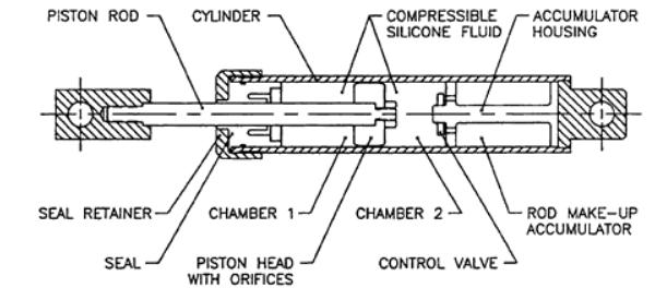
The main purpose of FVDs is to dampen a structure, which reduces structural response to seismic stimulation. From a lateral standpoint, FVDs can reduce displacement and narrative drift, which reduces the strain placed on structuralelements.FVDshave capacitytolessenthebase shear/overturning moment and the inter-story shear by reducingtheflooraccelerations.
FVDsarealsofrequentlysimplertoinstall,use,andmonitor than other devices. Design elements like internal fluid reservoirsandcutting-edgesealingtechniquesprolongthe life of damper designs. To help extend damper life and reducethelikelihoodofleavingastructureexposedwithout the necessary dampening in the case of a seismic event, a thorough health evaluation program includes monitoring alternativeslikefluidindicationsandcyclecounts.
And, long-term preventive maintenance strategy that includesFVDscanfrequentlybeaffordable.Whenstructural damageexpensesareincluded,theoriginalpurchaseprice represents only a small part of the damper's total worth, minimizingthecustomer'sentireinstallationexpense.
International Research Journal of Engineering and Technology (IRJET) e-ISSN:2395-0056
Volume: 09 Issue: 12 | Dec 2022 www.irjet.net p-ISSN:2395-0072
40.25m).Theyperformeda3Danalysisthatconsideredthe torsionaleffectusingtheResponsespectrumapproach.
P. Manjunath and Yogeendra R. Holebsgilu Inthis test, a ten story 3D display with four bayous in the Y directionandsixstraightsintheXdirectionisshown.The angleoftheground'ssloperangesfrom0°to30°.Themodel is broken down and planned using ETABS 2015 programming for different soil compositions and seismic zone V. They concluded that increasing the incline at the basecausestheseismicweighttodecreaseandincreasing thefirmnessofthegroundcausesthebuilding'sexecutionto increase.
Surekha Bhalchandra and Sandip Doijad (2015). In this study, they took into account the earthquake behaviourofRCbuildingsonlevelandslopingterrainwith variedsheardividerconfigurations.Theythoughtaboutthe G+8storyRCCbeingusedforaninvestigation.9o,18o,and 27o are the angles at which the slanting ground and level groundareexamined.UtilizingSAP2000programmingfor ZoneIIandmediumsoil,theexaminationwascompleted.
Chandrasekaran and Rao (2002); multi-storyRCC constructions' earthquake analysis and design were explored. It is quite challenging to model multi-story strengthenedconcretebuildingsasstructuralcomponents forstudy.Theyarefrequentlydepictedasslanted,inaplane, two-orthree-dimensionalframesystemswithvariedangles of5°, 10°,and15°.Comparethe instant,axial force, shear force,nodalmovement,stressesinthebeam,andsupporting reactiontothemostrecenteditionoftheIS:1893-2002to theearlierversionIS:1893-1984whenanalysingmultistory buildingsacrossthecountryforseismicforces.
Birajdar and Nalawade (2004); researched"the seismicresponseofstructureslyingonslopedterrain."We tookintoaccount24RCbuildingframesinthreedifferent arrangements: Step back building, Step back Set back building, and Set back building. The structures were positioned at a slope of 27 degrees. They looked into the seismic response of buildings in seismic zone III that had threebaysalongtheslopedirectionandonebayacrossthe slope,andhadstoreylevelsrangingfrom4to11(15.75mto
Ravikumar C. M et al (2012); focused on the “study of performance of irregular configuration of RC buildings”. They examined two distinct arrangements of structuresrestingonslopingground:structuressittingon sloped grounds in the X-direction and structures lying on sloping ground in the Y-direction. Inconsistencies in a building's geometry and buildings that were perched on slopeswerealsoexamined.Eachstructurehas5baysinthe XandYdirections,3storiesintheharshzoneV,and4bays in the X direction. ATC 40 nonlinear analysis and IS 1893 (part-1)2002linearanalysiswerebothusedtoanalysethe performance of these buildings. They discovered that structures on sloping ground are more susceptible to damagebecausetheyaredrawntopowerfulforcescausing them to moderately deform. The building perched on a hillsidehadabaseshearof6019.2kN,thatisapproximately 25–55%greatercomparedtootherstructures.Displacement was 83.4 mm, that was slightly more than comparable buildings'measurements.
Liya Mathew and C. PrabhaTitle: Effect of Fluid Viscous Dampers in Multi-Storied BuildingYear: 2014 This essay discusses how different loading conditions can affect buildings.Somenewandefficientprotectivetechniquesare createdwiththegoal ofpreventing buildingdamage from natural disasters like earthquakes. Here, the fluid viscose damper(FVD)issignificant.Inordertoreinforceconcrete frames,thispaperexplainshowtoidentifythemostharmful properties.UsingSAP2000softwares,analysiswascarried out in a symmetrical squares building. Results are graphicallycontrasted.
1 To identify the structure's displacement fluctuations bothwithandwithoutafluidviscousdamper.
2 To determine base shear variations in the structure by using fluid viscousdamperinRCbuildings.
3 To compare other parameters such as story drift, shear and displacement.
4 Comparingtheresultsalongandconcludingtheeffectof viscousdamperoverthebuildinginslope.
Inthedesignofaconstructivebuilding,loadsaredivided into dead loads and live loads. There were applied seismic loads,etc.
International Research Journal of Engineering and Technology (IRJET) e-ISSN:2395-0056
Volume: 09 Issue: 12 | Dec 2022 www.irjet.net p-ISSN:2395-0072
Buildingdesignstakeintoaccountdeadweight,which isspecifiedasamaterial'sunitweight.Forthepurposeof calculating loading, the total weight of many other substancesthatcanbehousedinstructuresisalsotakeninto account.DeadloadsareseenasbeingincludedinIS875Part 1.
Buildingdesignstaketheliveloadintoaccount.Itadds tothephysicalcontributionmadebypeople,theweightof thefurniture,andotherpiecesofequipment.Movingparts, distribution-focusedloads,impact,andvibrationloadsmake upthisload;air,earthquake,snow,andotherloadsarenot included.LiveLoads,Part2ofIS875.
The above combinations are taken into account whenastructureissubjecttoearthquakeforcesaccording to reinforced concrete structures' limit state design. followingIS1893-2002
1.5(DL±IL)
1.2(DL+IL±EL) 1.5(DL±EL) 0.9DL±1.5LL
Thetermsdeadload,imposedload,andintended seismicload,respectively,standforthereaction
Thisstudywasconductedinaneight-storybuilding. The floor plan is the same for all building models.The followinginformationisusedfortheanalysis:
GradeofConcrete:M45
Gradeofsteel:Fe550 Beam:600mm×450mm Column:600mm×600mm Onewayslab:200mm StoryHeight:3m
4.4Seismic Loads
TheIS:1893:2002seismicdesignmethodmustbe followed.ThebuildingissituatedinearthquakezoneV.For
analysisanddesign,thefollowingcriteriashouldbeutilized (perIS:1893:2002).(PartI).
SeismicZone:V
Zonefactor:0.36(ReferTable2) Importancefactor:1.0(ReferTable6)
ResponsereductionFactor:5.0(ReferTable7)
SoilType:Medium StructureType:RCFrameStructure
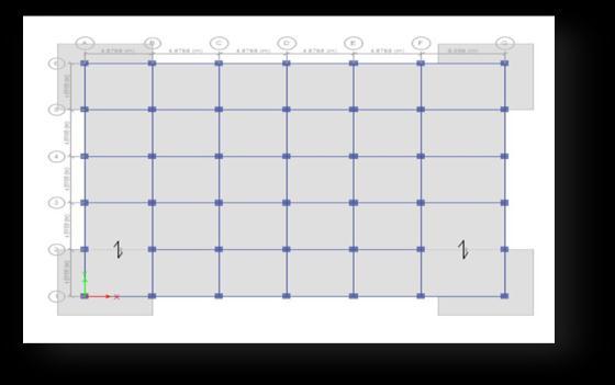
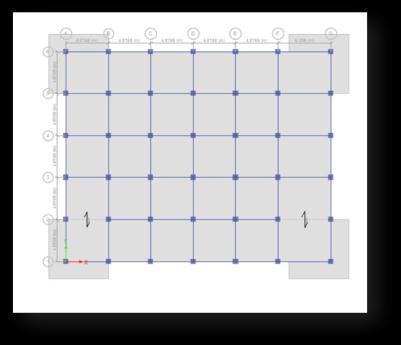
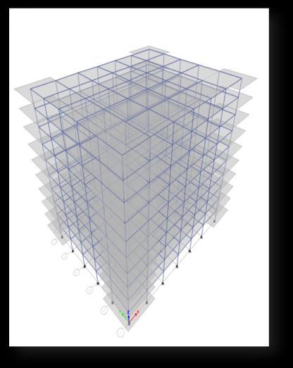
4.5 Layout of Buildings
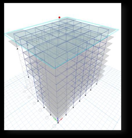
Fig -3:Planand3DModelofWireBuilding
International Research Journal of Engineering and Technology (IRJET) e-ISSN:2395-0056
Volume: 09 Issue: 12 | Dec 2022 www.irjet.net p-ISSN:2395-0072
regarding the design of a certain structure. For each structuralperiodthatthestructureexperiences,thereisa smoothcurvethatgivesthepressurewaveinaspectrafor thedynamicresponse.
Withtheexceptionofbasicorcomplicatedstructures, this strategy necessitates several building codes. The combinationofafewmodesinsideathreadthatvibratein response to the matching harmonics is a straightforward definitionofastructure'sreaction.Softwarecanthereforebe used to determine these approaches for a particular structure.Theresponseisdeterminedbyreadingthemodal mass or frequency for each mode from the design's spectrum. Consequently, x, y, and z directions should be examinedbeforetheimpactonthestructure.Thefollowing areexamplesofthecombinationmethod:
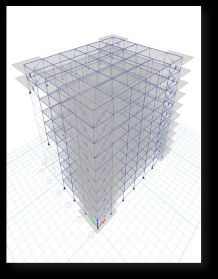
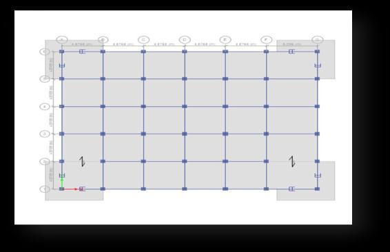
Fig -4:Planand3DModelofSlopedBuilding Fig -5:Planand3DModelofSlopedBuildingwithFVD
In order to determine the dynamic behaviour of a structure, this approach measures pseudo spectral acceleration,displacement,orvelocityusingdampinglevel and time history. This method is related to the kind of structure selection and is beneficial for making decisions
Addingtogethertheabsolute-peakvalues
Squarerootofthesumofthesquares
Combinationofcompletequadratic
5.RESULTS
ETABS is software used for analysis purpose and also in design of buildings. ETABS is characterised by powerfulgraphicalinterfacecoupledwithcommondatabase which is integrated with unmatched modelling, analysis, designanddetailingprocedures.
The maximum displacement occurred in the top storyofbuilding.ForEqx=22.741mmandEqy=23.659mm
WhencomparedwiththeEqxandEqyloadthereis 3.88%increased.
International Research Journal of Engineering and Technology (IRJET) e-ISSN:2395-0056
Volume: 09 Issue: 12 | Dec 2022 www.irjet.net p-ISSN:2395-0072
Themaximumstoryshear occurredinthebottom story of building. For Eqx=4682.561kN and Eqy=4761.579kN
WhencomparedwiththeEqxandEqyloadthereis 1.7%increased.
Chart -2: AutoLateralLoadsforEQX&EQY
Themaximumautolateralloadoccurredinthetop storyofbuilding.ForEqx=1246.71kNandEqy=1271.86kN
WhencomparedwiththeEqxandEqyloadthereis 2.0%increased.
5.2 Sloping Ground
Displacement
Themaximumstorydisplacementoccurredinthe top story of building. For Eqx=21.206mm and Eqy=19.553mm
WhencomparedwiththeEqxandEqyloadthereis 7.80%decreased.
Themaximumstoryshear occurredinthe story-5 ofbuilding.ForEqx=2073.627kNandEqy=2484.594kN
WhencomparedwiththeEqxandEqyloadthereis 16.54%increased.
Chart -4: AutoLateralLoads
Themaximumautolateralloadoccurredinthe topstoryofbuilding.ForEqx=1341.212kNand Eqy=1682.409kN
WhencomparedwiththeEqxandEqyloadthere is20.28%increased.
5.3 Sloping Ground with FVD Displacement
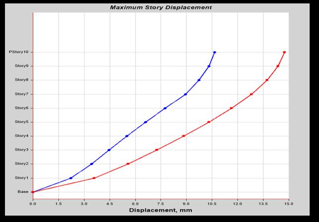
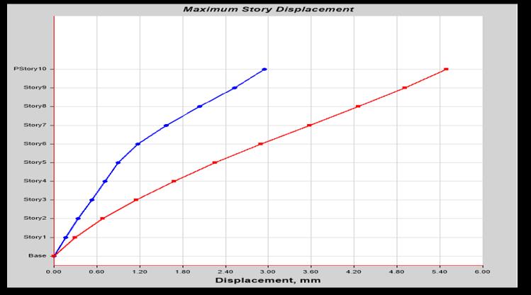
Chart -5: StoreyDisplacementforEQX&EQY
International Research Journal of Engineering and Technology (IRJET) e-ISSN:2395-0056
Volume: 09 Issue: 12 | Dec 2022 www.irjet.net p-ISSN:2395-0072
Themaximumstorydisplacementoccurredinthe topstoryofbuilding.ForEqx=9.401mmand Eqy=12.497mm
WhencomparedwiththeEqxandEqyloadthereis 24.77%increased
Themaximumstoryshear occurredinthe story-5 ofbuilding.ForEqx=1004.74kNandEqy=2140.146kN
WhencomparedwiththeEqxandEqyloadthereis 53.052%increased.
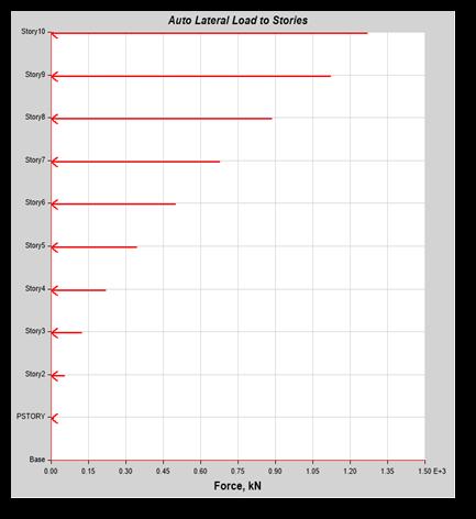
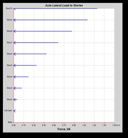
Chart -6: AutoLateralLoadsforEQX&EQY
Themaximumautolateralloadoccurredinthetop story of building. For Eqx=1222.711kN and Eqy=1222.711kN
BothEqxandEqyloadhavingthesameautolateral loads.
5.4 Comparison of Wire frame Building, Sloped Building and Sloped Building with Viscous Dampers Displacement
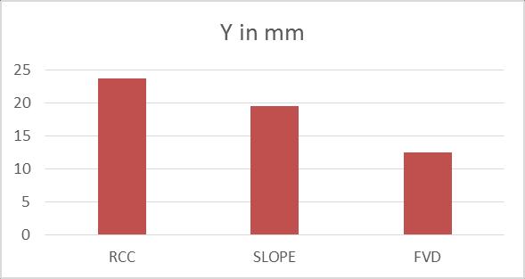
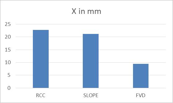
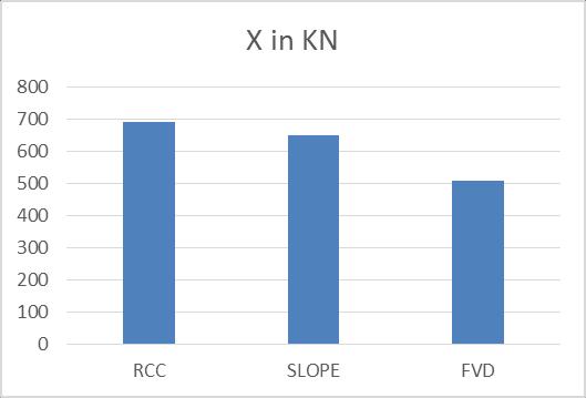
Chart -7: StoreyDisplacementforEQX
WhenweintroducetheFVDinthestructureinthe slopedareasthereismaximumreductionof55.66%
When compared with the normal and sloped buildingthereis6.74%decreased.
Table -2: DisplacementforEQY
in KN
Chart -8: StoreyDisplacementforEQY
WhenweintroducetheFVDinthestructureinthe slopedareasthereismaximumreductionof36.08%
When compared with the normal and sloped buildingthereis17.35%decreased.
International Research Journal of Engineering and Technology (IRJET) e-ISSN:2395-0056
Volume: 09 Issue: 12 | Dec 2022 www.irjet.net p-ISSN:2395-0072
Story Shear
Chart -9: StoreyShearforEQX WhenweintroducetheFVDinthestructureinthe slopedareasthereismaximumreductionof21.51% When compared with the normal and sloped buildingthereis6.12%decreased. Table -4: ShearforEQY MODEL Y in KN
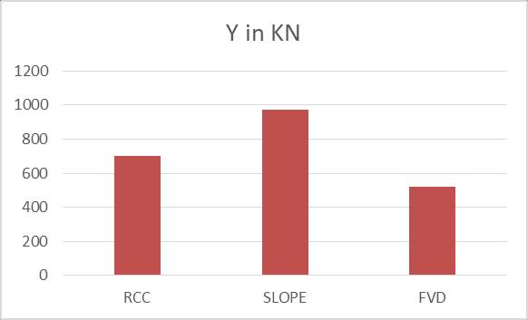
WhenweintroducetheFVDinthestructurein theslopedareasthereismaximumreductionof46.25%
Whencomparedwiththenormalandsloped buildingthereis27.71%increased.
Auto Lateral Loads
Table
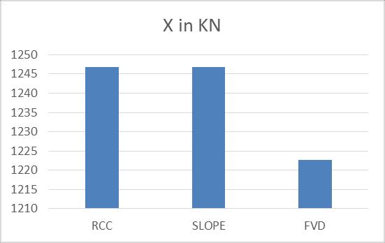
Chart -10: AutoLateralLoadforEQX
WhenweintroducetheFVDinthestructureinthe slopedareasthereismaximumreductionof1.92% When compared with the normal and sloped buildingthereisnochangeoccurred Table -6: AutoLateralLoadsforEQY MODEL Y in KN
International Research Journal of Engineering and Technology (IRJET) e-ISSN:2395-0056
Volume: 09 Issue: 12 | Dec 2022 www.irjet.net p-ISSN:2395-0072
2. S.Arjun and Arathi S (2016),“A study on dynamic characteristics of RC buildings on hill slopes”. International Journal of Science and Research 5(7):1116-1119.
3. Sivakamasundari,AJoshuaDaniel(2016),“Seismic vulnerabilityofbuildingonhillslope”.International JournalofEarthSciencesandEngineeringVolume 09,no.issue5(October2016):p.p.1892-1899.
4. K.Divya,ASrikanth(2018),“EffectofGroundSlope on Dynamic Performance of G+5 Building”, International Journal of Engg Reseach and Management,Volume5Issue8.
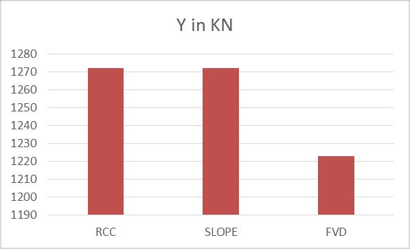
WhenweintroducetheFVDinthestructureinthe slopedareasthereismaximumreductionof3.86%
When compared with the normal and sloped buildingthereisnochangeoccurred.
1. Bycheckingthefinalcomparisonfordisplacement, driftandshearthefinalvaluesobtainedfortheall thethreereservesholdsgoodfordampermodel.
2. Consideringallthetablesandrespectivegraphwe foundthatcementdamperandsharewallperforms betterwhencomparedwithallothermodelswhich ishavinglessvalueandholdsgoodtoconsiderthe damper and shear wall model model performs better.
3. Consideringtheforcesvaluesthedamperperforms better as well as in drift analysis also the model performsbetter.
4. ConsiderintheshareforcestheRCCmodelwhichis theperformsbetterdamperandthenormalmodel appearstobeabetterchoicehenceinconsideration modelofdamperperformswellinconsideration.
5. Finally seeing all the three results displacement drift and story share values wecan conclude that thedampermodelisbetterinslopeconstructionof multistorywhencomparedwithallothermodel
1. B.G.Birajdar, and S.S.Nalawade (2004),“Seismic analysis of buildings resting on sloping ground,” Thirteenth World Conference on Earthquake Engineering(13WCEE),Vancouver,CanadaIS456 (2000).
5. R. B.Khadiranaikar, Masali A (2014),“Seismic performanceofbuildingsrestingonslopinggroundAreview”.IOSRJMechCivilEng1193):122-19.
6. Rahul Ghosh, Debbarma Rama (2019), “Effect of slopeangle variation on the structures resting on the hilly region considering soil–structure interaction”. International Journal of Advanced Structural Engineering. 11. 10.1007/s40091-0190219-3.