International Research Journal of Engineering and Technology (IRJET) e-ISSN: 2395-0056

Volume: 09 Issue: 12 | Dec 2022 www.irjet.net p-ISSN: 2395-0072
International Research Journal of Engineering and Technology (IRJET) e-ISSN: 2395-0056
Volume: 09 Issue: 12 | Dec 2022 www.irjet.net p-ISSN: 2395-0072
1 , Ali Dhaw
Aljadi2
1Department of Electrical Engineering, Faculty of Technical Sciences, Ben Walid, Libya
2Department of Electrical Engineering, Faculty of Technical Sciences, Ben Walid, Libya ***
Abstract - As solar generation increasesglobally,thereexists a need for innovation and increased operational flexibility. To ensure the stability and reliability in the electricity supply, power systems require complex dynamic analysis. Therefore, to carry out these analysis, modelling and simulationtoolsare needed. This paper focuses on approach is proposed to track the maximum power point (MPPT) of a photovoltaic system connected to utility grid. a free and open-source modelling and simulation environment based on Modelica language. In the later part, OpenModelica potential in large-scale power system-oriented models is investigated. These issues are addressed by a literature review concerning photovoltaic power systems and OpenModelica functionality, a theoretical analysis of a photovoltaic inverter and detailed simulations. The models are tested under variations in the active and reactive power requirements. The results show an optimal dynamic response and the capacity to perform independent active and reactive power controls. As an outcome, OpenModelica is a promising tool for power system modelling and simulation even though existing barriers and difficulties must be overcome.
cycle of buck converter, output of the buck converter is considered as the general load. It could be a battery or electricalload.
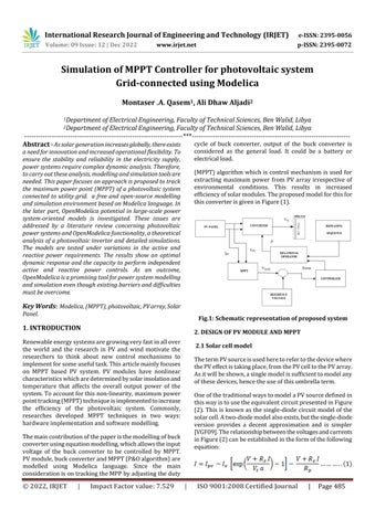
(MPPT)algorithmwhichis control mechanism isused for extracting maximum power from PV array irrespective of environmental conditions. This results in increased efficiencyofsolarmodules.Theproposedmodelforthisfor thisconverterisgiveninFigure(1)
KeyWords: Modelica, (MPPT), photovoltaic,PVarray,Solar Panel
Renewableenergysystemsaregrowingveryfastinallover the world and the research in PV and wind motivate the researchers to think about new control mechanisms to implementforsomeusefultask.Thisarticlemainlyfocuses on MPPT based PV system. PV modules have nonlinear characteristicswhicharedeterminedbysolarinsolationand temperature that affects the overall output power of the system.Toaccountforthisnon-linearity,maximumpower pointtracking(MPPT)techniqueisimplementedtoincrease the efficiency of the photovoltaic system. Commonly, researches developed MPPT techniques in two ways: hardwareimplementationandsoftwaremodelling.
Themaincontributionofthepaperisthemodellingofbuck converterusingequationmodelling,whichallowstheinput voltage of the buck converter to be controlled by MPPT. PVmodule,buckconverterandMPPT(P&Oalgorithm)are modelled using Modelica language. Since the main considerationisontrackingtheMPPbyadjustingtheduty
ThetermPVsourceisusedheretorefertothedevicewhere thePVeffectistakingplace,fromthePVcelltothePVarray. Asitwillbeshown,asinglemodelissufficienttomodelany ofthesedevices,hencetheuseofthisumbrellaterm.
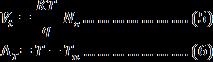
OneofthetraditionalwaystomodelaPVsourcedefinedin thiswayistousetheequivalentcircuitpresentedinFigure (2).Thisisknownasthesingle-diodecircuitmodel of the solarcell.Atwo-diodemodelalsoexists,butthesingle-diode version provides a decent approximation and is simpler [VGF09].Therelationshipbetweenthevoltagesandcurrents inFigure(2)canbeestablishedintheformofthefollowing equation:
International Research Journal of Engineering and Technology (IRJET) e-ISSN: 2395-0056
Volume: 09 Issue: 12 | Dec 2022 www.irjet.net p-ISSN: 2395-0072
In this equation, each of the terms take the following form:
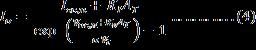
Fig .3:PVcellI-Vcurveatdifferentsolar
RadiationWhilefigure(4)showstheI-Vcharacteristiccurves of a photovoltaic cell at a constant solar radiation but differentambienttemperaturelevels
Where the values of Isc,n, KI, KV and Voc,n can be establishedfromthedata-sheet,thevaluesofthefollowing termsareknown:
Gn=1000W/m2andTn=298.15KaretheStandardTesting Conditions (STC) values of solar irradiation and temperature,respectively;k=1.3806503×10⁻²³J/Kisthe Boltzmann constant and q= 1.60217646 × 10⁻¹⁹ C is the electricchargeoftheelectron;NsandNparethenumberof cellsinseriesandinparallel,respectively;finally,G,Tare the actual solar irradiation and ambient temperature, normallyconsideredinputstothemodel,andIandVarethe actualpanel/arraycurrentandvoltage.
Figure (3) shows the I-V characteristic curves of a photovoltaic cell at a constant ambient temperature but differentradiationlevels.
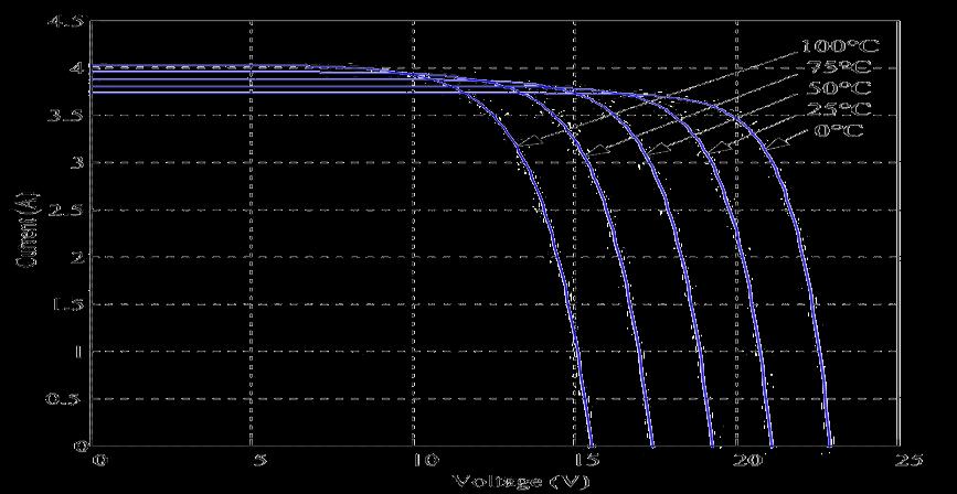
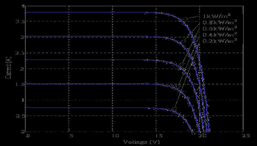
Fig .4:PVcellI-Vcurveatdifferenttemperature
Figure(5)showstheI-Vcharacteristicofthesolarcell fora certain ambient irradiation Ga and a certain fixed cell temperature Tc
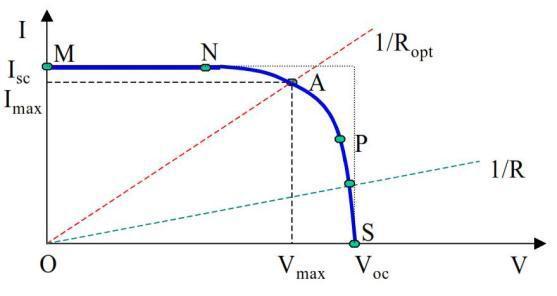
IntherepresentationofI-Vcharacteristic,asignconvention isused,whichtakesaspositivethecurrentgeneratedbythe
International Research Journal of Engineering and Technology (IRJET) e-ISSN: 2395-0056
Volume: 09 Issue: 12 | Dec 2022 www.irjet.net p-ISSN: 2395-0072
cellwhenthesunisshiningandapositivevoltageisapplied onthecell’sterminals.
Ifthecell’sterminalsareconnectedtoavariableresistance R,theoperatingpointisdeterminedbytheintersectionof the I-V characteristic of the solar cell with the load I-V characteristic-seefigure(4).Foraresistiveload,theload characteristic is a straight line with a slope I/V=1/R. It shouldbepointedoutthatthepowerdeliveredtotheload dependsonthevalueoftheresistanceonly.
Asknown,thePVarraysproduceDCpowerandtherefore whenthestand-alonePVsystemcontainsanACload,asitis the case for the inverter tied to grid system, a DC/AC conversionisrequired.Thisisthusthereasonwhythispart briefly presents the inverter. An inverter is a converter wherethepowerflowisfromtheDCtotheACside,namely having a DC voltage, as input, it produces a desired AC voltage,asout-put–seeFigure(6).
point Tracking (MPPT) techniques are available in the present era and among all these techniques P&O and incrementalconductancealgorithmsaregenerallyusedin PVsystemforobtainingmaximumpowerpoint.
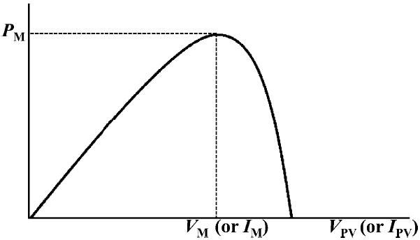
In Figure. (7), Pm is the maximum power that can be obtained from a particular panel. The aim of a MPPT algorithmistotrackPmbymakingVPVtoVMorIPVtoIM.
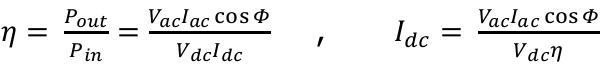
The inverter is characterized by a power dependent efficiencyη.TheroleoftheinverteristokeepontheACside thevoltageconstantattheratedvoltage230Vandtoconvert the input power Pin into the output power POut with the bestpossibleefficiency.Theefficiencyoftheinverteristhus modelledas:
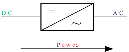
Fig.7: Power–voltagecharacteristicsofphotovoltaic systems.
ThePerturbandObserve(P&O)algorithmoperatesperturbs the PV voltage periodically by varying the duty cycle, and observesthePVpowertoincreaseordecreasePVvoltagein the next cycle. If the perturbation voltage produces an increase of the power, then the direction or slope of perturbation voltage. On the contrary, if the perturbation voltageproducesadecreaseofthepower,thenthedirection orslopeofperturbationvoltage(dutycycle)istheopposite fromthepreviouscycle
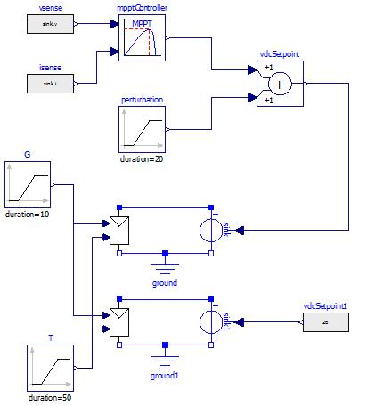
The system is simulated using Modelica is shown in Figure(8),theinputofPV-moduleblockisVa(PVvoltage), Suns(irradiation),andTaC(operatingtemperature).
WhereIdcisthecurrentrequiredbytheinverterfromthe DCside(forexample,fromthecontroller)inordertobeable tokeeptheratedvoltageontheACside(forexampleonthe load).Vdcistheinputvoltagefortheinverterdeliveredby theDCside,forexamplebythecontroller.
TheMaximumPowerPointTracking(MPPT)isatechnique bymeansofwhichmaximumpowercanbeextractedfrom the Photovoltaic (PV) Systems. To improve the energy efficiency, it is relevant to operate the total PV module alwaysatitsmaximumpowerpoint.Manymaximumpower
Fig.8: ModelofPVsystemwithMPPT&PIcontroller
International Research Journal of Engineering and Technology (IRJET) e-ISSN: 2395-0056
Volume: 09 Issue: 12 | Dec 2022 www.irjet.net p-ISSN: 2395-0072
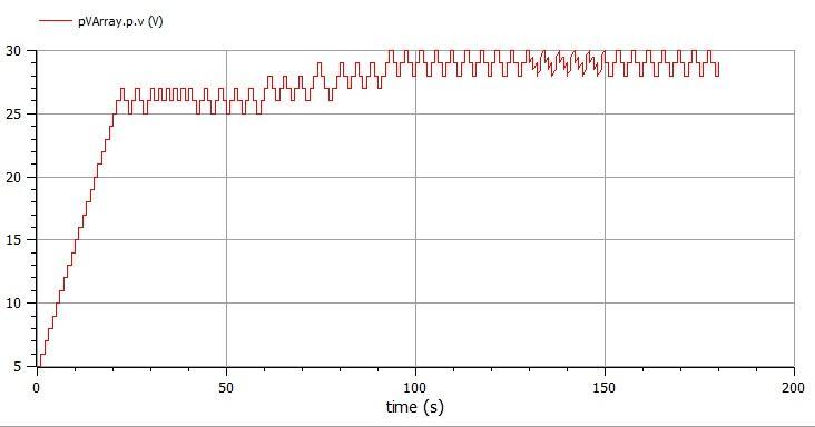
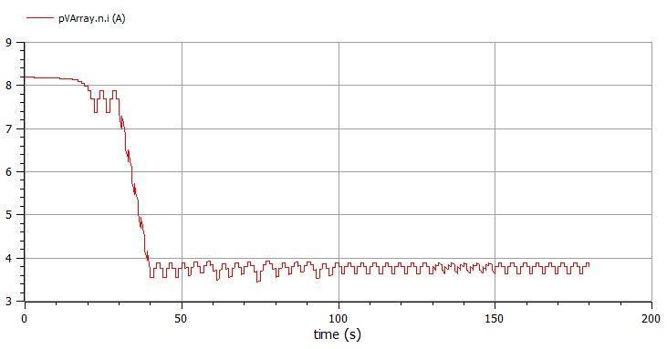
Figure(9)andfigure(10)exhibitthecurrentandthevoltage ofthephotovoltaicarray.Itisclearthatwhentheirradiation conditions change, the current increases (or decreases) significantlyandthePVoutputvoltagechangesslowly.
Herethestand-alonesolar-PVgenerationsystemwithCUK converterhasbeendesignedandtheperformanceanalysis ofthesystemhasbeenpresentedusingModelicasoftware withdifferentirradiance.Fromthesteadystateanalysisit canbeobservedthatthesystemattainsthemaximumpower point tracking successfully despite of fluctuations in insolation.Thesystemcantrackthemaximumpowerpoint veryquicklywhentheenvironmentalconditionchanges.
Fig.9: Photovoltaiccurrent.
OpenModelica performance in the studied power system modelsmaynotbestillcompetitivewiththedomain-specific tools. However, consider OpenModelica limited resources compared to conventional commercial power systems software. Modelica is also developed with compensability and reusability in mind, with the inclusion of object orientation and causal equation based modelling and connection of components. This makes it easy to create modelsintegratingseveralphysicaldomains.
[1]Huan-LiangTsai,Ci-SiangTu,andYi-JieSu,Development ofGeneralizedPhotovoltaicmodelusingmatlab-simulink.
[2] Jihad Bou Merhi, Jana Chalak, and Joya Zeitouny, EstimationofBatteryInternalParameters.
[3] Anca D. Hansen, Poul Sørensen, Lars H. Hansen and HenrikBindner,Modelsforastand-alonePVsystem.
[4]S.W.Angrist,DirectEnergyConversion,AllynandBacon, Inc.,4thedition,1982,pp.177-227.
Fig.10: Photovoltaicvoltage
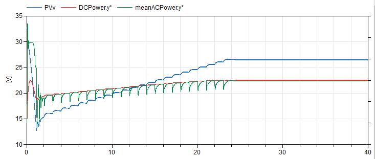
Figure(11)depictsthevoltageandcurrentwaveformofVSC, connectedtoutilitygrid.Smallharmonicsareobservedin thegridcurrentwaveform.Theseharmonicsareduetothe current injection by the semiconductor devices like wise IGBTbasedVSC.AsexpectedthevoltageandthecurrentVa and Ia are in phase. Therefore, the system provides thepowertoutilitygridwithunitypowerfactor.
[5]J.C.H.Phang,D.S. H.Chan,andJ.R.Philips,“Accurate analytical method for the extraction of solar cell model parameters,” Electronics Letters, vol. 20, no. 10, 1984, pp.406-408.
[6] Massimo Ceraolo, Tarun Huria, Rechargeable lithium battery energystoragesystemsforvehicularapplications, PHDthesis.
[7] R. A. Huggins, “Advanced batteries: materials science aspect”,Springer,2008.ISBN0-3877-6423-2
[8]Abdelhalim Zekry, A. Alshazly, A. Abdelrahman, Simulationandimplementationofgrid-connectedinverters, International Journal of Computer Applications (0975 –8887),Volume60–No.4,December2012.
[9]PallaveeBhatnagar,R.K.Nema,Maximumpowerpoint trackingcontroltechniques;State-of-the-artinphotovoltaic applications.
Fig.11:outputpowertotheinverter
International Research Journal of Engineering and Technology (IRJET) e-ISSN: 2395-0056 Volume: 09 Issue: 12 | Dec 2022 www.irjet.net p-ISSN: 2395-0072
[10] Z.M. Salameh, M.A. Casacca, W.A. Lynch, “A Mathematical Model for Lead-Acid Batteries”, IEEE Trans. Energy Conversion, vol. 7, issue 1, pp. 93-97, Mar. 1992, doi:10.1109/60.124547.
[11]M.Chen,G.A.Rincon-Mora,“Accurateelectricalbattery modelcapableofpredictingRuntimeandI_VPerformance,” IEEETrans.EnergyConversion,vol.21,no.2,pp.504-511, Jun.2006,doi:10.1109/TEC.2006.874229.
[12] Ceraolo, M., “New Dynamical Models of Lead-Acid Batteries”, IEEE Trans. Power Systems, vol. 15, no. 4, pp. 1184-1190,Nov.2000,doi:10.1109/59.898088.
[13]KobayashiK,TakanoI,SawadaY.Astudyonatwostage maximum power point tracking control of a photovoltaic systemunderpartiallyshadedinsolationconditions.In:IEEE Power Engineering Society General Meeting 2612–2617.2003.
[14]AlNabulsiA,DhaouadiR.Efficiencyoptimizationofa DSP-basedstandalonePVsystemusingfuzzylogicanddualMPPTcontrol.IEEETransactionsonIndustrialInformatics 2012;8(3):573–84.
[15]TekeshwarPrasadSahu,T.V.DixitandRameshKumar,‖ Simulation and Analysis of Perturb and Observe MPPT Algorithm for PVArrayUsingĊUKConverter‖Advancein Electronic and Electric Engineering. ISSN 2231-1297, Volume4,Number2(2014),pp.213-224.