International Research Journal of Engineering and Technology (IRJET) e-ISSN: 2395-0056

Volume: 09 Issue: 12 | Dec 2022 www.irjet.net p-ISSN: 2395-0072
International Research Journal of Engineering and Technology (IRJET) e-ISSN: 2395-0056
Volume: 09 Issue: 12 | Dec 2022 www.irjet.net p-ISSN: 2395-0072
1Final year M.Tech student Dept. of Mechanical engineering, VJIT college, Hyderabad, Telangana, India 2Associate professor Dept. of Mechanical engineering, VJIT college, Hyderabad, Telangana, India, 3Assistant professor Dept. of Mechanical Engineering, Guru Nanak Institute Technical Campus, Hyderabad, India, ***
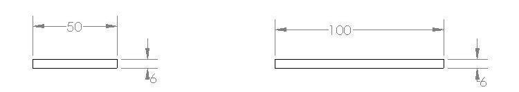
Abstract - The present work investigates the Effect of TiO2 nanoparticles on friction stir welded joints of AA8011 aluminium alloys. In this test 100x50x6mm dimensioned plates of AA8011 aluminum alloys are used test for FSW, where the tool rotates on the edges of two plates to give a complete the weld joint. Here, Titanium dioxide nanoparticles were added into the grooveofsize2.5mm(W)×5mm(H) before the welding process and the welding tool is moved along the edges of similar aluminium alloys AA8011 onsemi-automated milling machine to complete the welded joint. Tool geometry depends on probe length, shoulder size and pin shape which influences the heat generation and material flow in the hard condition. The shoulder produces high heat which plasticizes the material and the welded joint can form effectively in the solid state. Here the welding tool with hexagonal pin is used effectively, which improves mixing of nanoparticles in the stir zone. As it is clear from the literature the strength of the friction stir welding joint is higher than the conventional fusion welding process. The strength of the welded joint in FSW depends on the process parameters like rotationalspeed, welding speed, axial load and tilt angle. In order to further enhance the mechanical properties of the welded joint, the microparticles can be deposited during welding process. So, in this study we evaluate the mechanical properties and microstructure of the welded joints.
A comparison has made between the experimental values and the recently published journal papers. The maximum peak stress obtained was 52.98 MPa at 1400RPM, welding speed of 25mm/min and tilt angle of 1.50. The maximum impact value obtained was 5.0 joules weld 8, maximum Microhardness of 22.79 VH average for weld8.
Keywords:Aluminium alloys AA8011, TIO2 nanoparticles, SEM, Friction Stir welding, Microstructure and Mechanical properties, modified Tool.
The friction stir welding (FSW) may be a new welding techniqueindomainofwelding.it'ssolidconditionwelding process and invented by the welding institute (TWI) of Cambridge, England in 1991. This procedure is easy, environmentfriendly,energyefficientandbecomesmajor attractionforanautomobile,aircraft,marineandaerospace
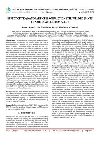
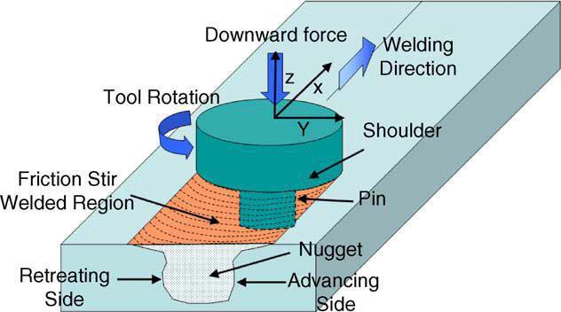
industriesbecauseofthehighstrengthoftheFSWjointsas nearasbasemetal.Itallowsconsiderableweightsavingsin light weight construction compared to standard joining technologies. In contrast to standard joining welding process,there'snoliquidstatefortheweldpoolduringFSW, the welding takes place within the solid phase below the freezing point of the materials to be joined. Thus, all the issuesassociatedwiththesolidificationofafusedmaterial areavoided.Materialswhicharedifficulttofusionweldjust likethehighstrengthaluminiumalloysmaybejoinedwith minor loss in strength. In friction stir welding a nonconsumablerotatingtoolwithaspeciallyprofiledthreaded/ unthreadedpinandshoulderisrotatedatarelentlessspeed. Thetoolplungesintothe2piecesofsheetorplatematerial and thru frictional heat it locally plasticized the joint region.Thetoolthenallowedtostirthejointsurfacealong the joining direction.During tool plunge, the rotating tool undergoes only rotational motion at only 1 place till the shoulder touches the surface of the work material, this is oftencalledthedwellingperiodofthetool.Duringthisstage oftoolplungeitproduceslateralforceorthogonaltowelding or joining direction.the subsequent diagram depicts the proceduresofFSW.Thesideoftheweldconsistsoffabric that'sdraggedbytheshoulderfromtheretreatingsideofthe weld,anddepositedontheadvancingside.Afterthedwell period the tool traverse along the joining direction, the advanceofthetoolproducesforceparalleltothedirectionof travel called traverse force. After the successful weld, the toolreachestoterminationphasewhereit'swithdrawnfrom the work piece. this can be shown in fig. 1.1. During the welding process the parts must be clamped rigidly onto a backing bar in an exceedingly manner that forestalls the abuttingjointfacesfrombeingforcedapart.Thelengthof thetoolpinisslightlybutthewelddepthrequiredandalso the tool shoulder should be in intimate contact with the surface.Besidestightclampingofthememberstobewelded, the key to success is to pick out the optimum parameters whichincluderotationalspeed,weldingspeed,axialforce, andgearpinyetasshoulderprofile.Detaileddescriptionof FSWprocessisshowninFig.1.2.
International Research Journal of Engineering and Technology (IRJET) e-ISSN: 2395-0056
Volume: 09 Issue: 12 | Dec 2022 www.irjet.net p-ISSN: 2395-0072
is done in Engineer. Structural and modal analysis is performed on the circular and taper tool to validate the deformation and stresses. By study the results, stresses produced are decreased circular tool. Two plates of the AA5083andAA6061areweldedexperimentallyonavertical CNCmachineusing700rpmspeedforcircularcuttingtool. Tensilestrength,microstructure,impactandhardnessare calculated after welding. By scrutinize the tensile test results;ultimatetensilestrengthisdecreasingbyincreased andhardnesstestresults,theyieldstressvalue51.43MPa.
Ankur S Vasava et al. inthisreviewstatedadvantagesof FSWthatlowdistortion,shrinkages,fullermetal,lowHAZ, freespotter,porosityetcemergingasontofusionwelding.
Fig. 1.1: Schematic representation of FSW
Arun kumar kadian et al. foundthattaperpintoolduring lowquantityofmaterialmixingthancylindricaltoolandalso reducetheutmostheatobtainedbytheweld.Cylindricaltool pininFSWproducedfinemicrostructure.
Noor Zaman Khan et al.studiedtheeffectsofstrainrate& heatagegroupontraverseforceinFSWofAA2219,AA7475 aluminiumalloys,Thisworkhasattempttoestimatestrain ratethroughmeasuredvaluesofgrainsizeandweldingheat and found its correlation with flow stress. The following conclusionsaredrawninlightofthegradesoftheconducted experimentalinvestigation
Fig. 1.2:
Hou and Baeslack 1996, Aluminiumisoneofthematerials whicharenoteasytojoinbyfusionweldingmethods.Thisis duetothelowmeltingindicatingandlowhardnessofthe material.Conventionalfusionweldingprocesssuchasmetal inertgas(MIG)andplasma arc welding(PAW)frequently create adverse cast microstructures in aluminium. Big distortionsarecausebyshrinkageinweldmetalandheat affected zones. In adding together widespread soften will happenintheHAZ,loweringthemechanicalproperties.
D. Maneiah and Prahlada Rao performedtheexperimental examination on friction stir butt welded aluminum alloys AA6061-T6 alloy using taguchi L9 untried approach The aluminum 6061-T6 alloy is successfully welded by the friction stir welding process. The Taguchi optimization is performed where the optimum conditions are rotational speed1000to1250RPM,tiltangle0.5to1degreeandfeed 30to60mm/minfortheresponsetemperature170°C.And for the response hardness at the weld bead the optimum conditionsarerotationalspeed750to1250RPM,tiltangle 0.5 to 1 degree and feed 60 to 90 mm/min, where the hardnessisfoundtobehigheri.e.95BHN.
Dr. Ch.S.Naga Prasad et al. performedInthisprojectcutting tooltaperisdesignedfortheFSWoftwodissimilarmaterials Aluminiumalloy5083andaluminiumalloy6061.Modelling
Ravinder Reddy Baridula et al. studied the dissimilar aluminiumalloysAA2024andAA7075byadditionof multiwalled carbon nanotubes in to the nugget zone. The mechanicalpropertiesandmicrostructureswerecalculated byvaryingthetraversevelocityatstablerotationalvelocity. The results show that revolving tool pin stirring act and temperatureinputplayanimportantfunctionincalculating thegrainsize.
Thischapterincludesthedetailsoftheexperimentcarried outtofulfilltheobjectiveofthisinvestigationoffrictionstir welding by using hexagonal tool pin with titanium nano particlespowderfilledinsimilarworkpiecesbeforewelding process and by moving the welding tool on edges of both platesweldedjointwasobtainedtowirecutEDMfordesire standard shape. To get the results Mechanical testing like tensiontest,impactizodtest,microhardnesstestwasdone tounderstandtheinfluenceofnanoparticlesonweldedjoint.
Aluminium alloy: Aluminium is the world most usable metalandthethirdmostcommonelementcomprising8%of theearthscrust.Aluminiumalloyduringthe97% byadding chemical composition with copper, iron, magnesium, manganese,silicon,tinandzinc.
AA8011 which is commonly used household foil is an attractive material due to the fact that it can provide a
International Research Journal of Engineering and Technology (IRJET) e-ISSN: 2395-0056
Volume: 09 Issue: 12 | Dec 2022 www.irjet.net p-ISSN: 2395-0072
suitable combination of strength and ductility agent in aluminiumalloyAA8011aretheironandsiliconconstituent particles.
The Similar material aluminum alloy AA8011 was usedin this investigation. Chemical compositions of the alloy materialaregivenintheTable.1.Mechanicalpropertiesof aluminumalloyweregiveninTable.2.TheSimilaraluminum alloyusedinthisinvestigationwasweldedusingFrictionstir weldingtechnique.
Table 2.1: Chemical composition of AA 8011 aluminum alloys
Fe Si Mn Mg Zn Cu Ti Cr Al
AA 8011 0.74 0.52 0.460.28 008 01 001 002 Rem
Table 2.2: Mechanical properties of AA 8011 aluminum alloys
MECHANICAL PROPERTIES Tensile Strength MPa
Density Kg/m3 Thermal conductivity W/m-k
Melting point C
Hardness HRB
AA 8011 110 2689 237 660.2 60
Table 2.4 chemicalcompositionofH13metal.
Element C Ch Mn P Si S V Percenta ge.(%) 0.30.4 4.75 0.20.5 0.00.3 0.81.2 0.00.3 0.81.2
Table 2.5 PhysicalpropertiesofH1material
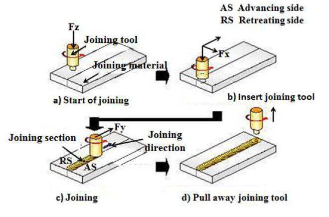
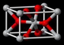
Titanium oxide powder (TIO2): TIO2 which mean it consistsofonetitaniumatomandtwooxygenatoms(hence dioxide).Titanium foundmineralsintheearth’scrust. It’s also found with other element. Its having good tensile strengths.
Table 2.0 propertiesofTIO2powder
Properties Values
Density 4.23g/cm3
Meltingpoint 1843 oC
Boilingpoint 2972oC
Solubilityinwater insoluble
Bandgap Magnetic susceptibility
3.05eV 5.9x10⁻⁶ cm3/mol.
Properties of H13 Density Meltingpoint Thermalexpansion Thermalconductivity
Values 7.80g/cm3 1427 oC 10.4x10⁻⁶/ºC 28.6W/mK
Properties of H13 Values
Tensilestrength,(@20°C) 1200-1590MPa
Modulusofelasticity 215GPa Reductionofarea(@20°C/68°F) 50.00%
Tensilestrength,yield 1000-1380MPa.
International Research Journal of Engineering and Technology (IRJET) e-ISSN: 2395-0056
Volume: 09 Issue: 12 | Dec 2022 www.irjet.net p-ISSN: 2395-0072
AA8011
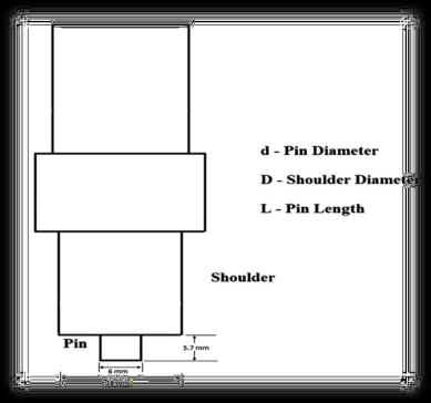
Table 2.3:
Details Dimensions
PinLength,L(mm) 5.7
Toolshoulderdiameter,D(mm) 22
Pindiameter,d(mm) 10
D/dRatiooftool 3.0
Toolpingeometry Circular
Pitch(mm)andincludedangle (deg)of threadedpin
Chemical composition of the tool(wt%)
1and60
C-2.75, Si-0.60 max, Mn0.60max Cr-13.5, Ni-.30 max, Grade- D3 (HSS)
Details Dimensions
PinLength,L(mm) 5.7
Toolshoulderdiameter,D(mm) 22
Pindiameter,d(mm) 10
D/dRatiooftool 3.0
Toolpingeometry Circular
Pitch(mm)andincludedangle (deg)of threadedpin
Chemical composition of the tool(wt%)
1and60
C-2.75, Si-0.60 max, Mn0.60max Cr-13.5,Ni-.30max,Grade-D3 (High carbon steel High ChromiumSteel)
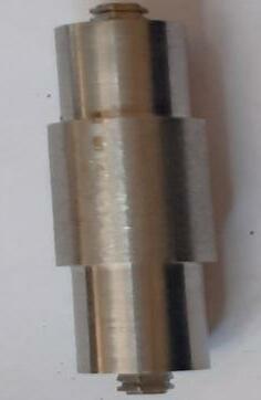
TherearemanytypesoftoolmaterialsavailableforFSW.In this experiment hexagonal shape high carbon high chromium tool was used. Dimensions and chemical compositionofToolwillbegiveninthebelowtable.
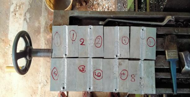
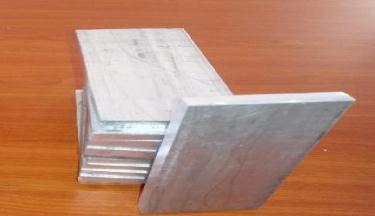
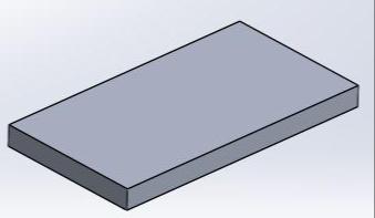
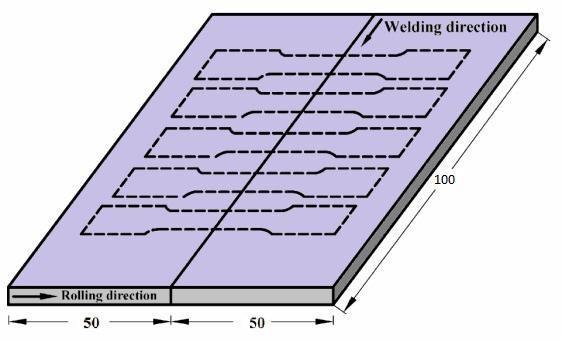
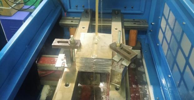
Theplatesof6mmthicknessAA8011aluminumalloyswere cut into required sizes (50 mm width x 100 mm length) usingpowerhacksaw.Asquarebutjointconfigurationwas prepared to carry out the FSW joints. The initial joint configurationwasobtainedbysecuringtheplatesinposition using mechanical clamps. The direction of welding was normaltotherollingdirection.Nonconsumabletoolmade upofHighcarbonHighChromiumSteelwasusedforjoining process. The aluminum alloys were joined by varying rotational speed in four levels namely 1400, 1120, 1400, 1120 and traverse speed in three levels namely 35, 25mm/minwiththeaxialforceof15KN.Thetoolusedfor fabricatingthejointsismadebyHighcarbonHighChromium Steelofdiameter25mmwithshoulderdiameteras22mm and with a cylindrical pin of diameter 6mm. With the identified process parameters, the joints were fabricated. The fabrication process will be given in tool Figure2. As showninFigure.3thedirectionofweldinghasbeennormal totherollingdirection.Singlepassweldingprocedurehas beenfollowedtofabricatethejoints.
International Research Journal of Engineering and Technology (IRJET) e-ISSN: 2395-0056
Volume: 09 Issue: 12 | Dec 2022 www.irjet.net p-ISSN: 2395-0072
Electrical discharge machining is a metal fabrication process whereby required shape is obtained by using electrical discharges material is detached from the work pieceofquicklyfrequentcurrentdischargesbetweentwo electrodes, divided by dielectric liquid and subject to an electricvoltage.Oneoftheelectrodesistoolelectrodeand other one is named work piece electrode. The process depend on the tool and work piece not making physical contact,andit’scontrolledbyCADprogram,herethetool electrodeissimplyawire.
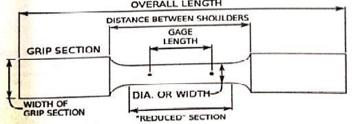
A tensile test is the most essential and usual types for mechanicaltestingofmaterial.Intensiletestapullingforce is applied to a material and finds out the specimens responsetothestresscreatedinit.Byconductingtensile testsonecanknowhowstrongamaterialistoloadapplied toitandhowmuchitcanelongatewiththeloadapplied.A tensiletestismainlyconductedonUTM-UniversalTesting MachineandthetensilespecimenisofstandardASTME8 (Americansocietyfortestingofmaterial)i.e.standarddog bone shape sample as shown in the figure 3.20. The test resultsareplottedonagraphwherethisdataresultsina stress/straincurvewhichtellshowtheSpecimenrespond totheforcesappliedtoit.Intensiletestthepointofbreak orfailuresisverycrucialpointtobenoted,otherimportant propertiesalongwithbreakorfailurepointistheelasticity, peakstress,peakload,yieldstrain,yieldload,etc.
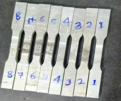
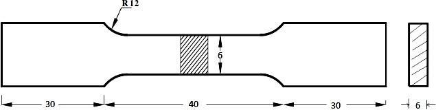
ASTM E8: ASTME8Tensionspecimen(DogBoneShape)is madeouttheFSweldedspecimeninrectangularshoulder with 40mm gauge length with the help of EDM wire cut machine where a wire is passed through the welded specimenbasedonthepathinformationgiventoit.ADog BoneShapeinputdataisgiventoitandworksaccordingto theinputcommand.
International Research Journal of Engineering and Technology (IRJET) e-ISSN: 2395-0056
Volume: 09 Issue: 12 | Dec 2022 www.irjet.net p-ISSN: 2395-0072
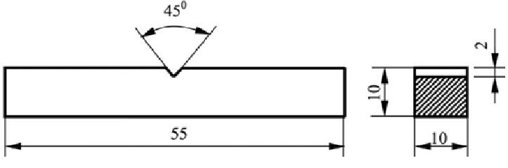
The Impact Test entails protest a notched impact specimen with a wavering weight or a “tup” attached to a swinging pendulum. The specimen breaks at its notched cross-section upon impact, and the upward swing of the pendulumisusedtoregulatetheamountofenergyabsorbed (notch toughness) in the process. Energy absorption is directly related to the brittleness of the material. Since temperature can affect the toughness of a material, the charpytestisexecutedataseriesoftemperaturestoshow the relationship of ductile to brittle transition in rivetted energy. ASTM E23 standard to EDM wire cut for charpy impacttestshownthebelowfigure.
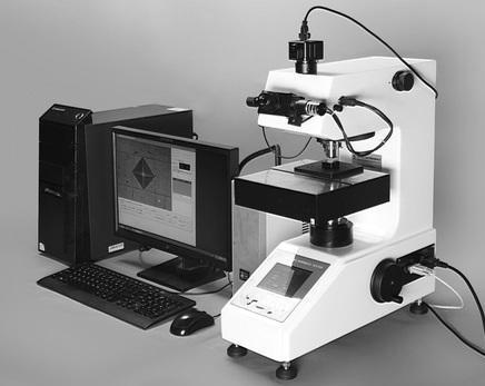
Micro hardness Testing is a technique of defining a material’shardnessorresistancetopenetrationwhentest samples or specimen are very small, thin and when small regions in a composite sample or plating are to be investigatedormeasured.Microhardnesstestcanprovide preciseanddetaileddataaboutsurfacefeaturesofmaterials that have a fine microstructure, multi-phase, nonhomogeneousandalsopronetocracking.Bymicrohardness testonecanmeasurepreciselysurfacetocorehardnesson carburized and case-hardened parts, as well as surface conditions such as grinding burns, carburization or decarburization. Micro hardness test specimen testing is carriedonthespecimenonwhichtheMicrostructurestudyis carriedout.
Figure 2.12:DigitalVickershardnesstester
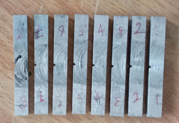
Figure 2.13: micro hardness test samples from EDM wire cut
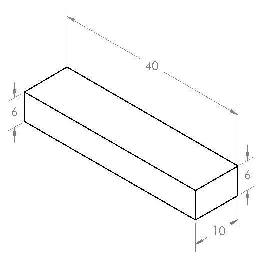
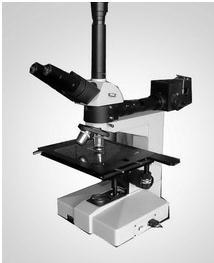
MetallographicMicroscopeexaminationwasdoneinCrystal metallurgicallaboratoryinHyderabad.Eightflatsampleof thickness 6mm and overall length of 40mm and width is
International Research Journal of Engineering and Technology (IRJET) e-ISSN: 2395-0056
Volume: 09 Issue: 12 | Dec 2022 www.irjet.net p-ISSN: 2395-0072
10mm from welded specimen are used for metallographic examinationtostudytheMicrostructureofthespecimen.The welded sample is trimmed or machined based on the requireddimensionforconductingtheMetallographictestto studymicrostructureonaEDMwirecutmachineinsucha waythatbettermicrostructurecanberevealed.Thepolished samples were etched with Keller’s Etching agent used for Aluminium for 15 minutes to reveal microstructure. The microstructure of samples was examined by using optical Microscope. These different zone in specimen study were primarily characterized into(a)Weld zone or Nugget Zone and b) TMAZ c) HAZ zone and finally the parent material Zone.
Inexperimentalinvestigationofprojectisdonetheresults and comparing by the result with standard papers mentionedintheLiteratureReviewofthisproject,journal, withstandardparameterslikehowandwhatisthepercent ofvariationwithrespecttostandardoneofexaminationthe results of friction stir welded of aluminum alloys by the addition of reinforcements are given below, it has been observedthattheprocessparametersplayanimportantrole duringofmetalsbyFSWprocess.
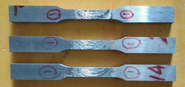
Tensile test was conducted by using UTM and the resultsaregiveninfollowingtable4.1.Theparameterrange oftoolrotationalspeed1400rpmandweldingspeedof25 mm/min and tilt angle 1.50 can gives the high range of TensileStrengththanotherparameters.Thetensilesamples afterthetestareshowninthefigure4.1below.Thereading obtainedwhileperformingthetensiletestareshownbelow intable4.1:
International Research Journal of Engineering and Technology (IRJET) e-ISSN: 2395-0056
Volume: 09 Issue: 12 | Dec 2022 www.irjet.net p-ISSN: 2395-0072
Table 3.1: Showing Reading Recorded while tensile test
TENSILE TEST RESULTS
Identification of the Sample
Tool rotation speed RPM
Weld speed mm/min
Tilt angle o
C/S Area (mm2)
Ultimate Load (KN)
UTS (MPa) Yield Strength (MPa) % Elongation Results/ Remarks
Weld ‘1’ 1120 25 1 37.50 1.48 39.48 30.13 09.24
Weld ‘2’ 1400 35 1 35.82 1.20 33.50 31.27 09.96
Weld ‘3’ 1120 35 1 36.36 0.80 22.00 09.90 05.72
Weld ‘4’ 1400 25 1 33.33 1.24 37.09 32.30 06.40
Weld ‘5’ 1120 25 1.5 37.50 1.20 32.00 26.67 05.92
Weld ‘6’ 1400 35 1.5 37.27 1.16 31.12 2.68 07.20
Weld ‘7’ 1120 35 1.5 36.36 0.82 22.01 09.94 05.71
Weld ‘8’ 1400 25 1.5 34.75 1.84 52.95 34.53 08.12
Calculating Strain using %Elongation:
GaugeLength=40mm(initiallengthL1) L2=finallength
Therefore: L1–L2/L1=16
AftercalculationL2=43.2mm
Fromabovecalculationwecanknowthatafterbreakthefinalgaugelengthis43.2mm.
Note: The displacement vs load curve for ten samples as shown below graphs:
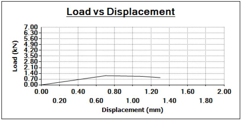
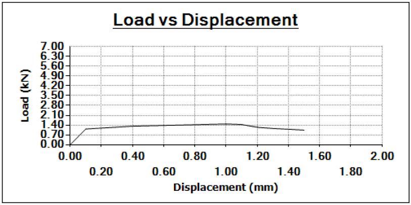
Graph1:Sample1
Graph2:Sample2
Brokenin WeldZone
International Research Journal of Engineering and Technology (IRJET) e-ISSN: 2395-0056
Volume: 09 Issue: 12 | Dec 2022 www.irjet.net p-ISSN: 2395-0072
Graph3:Sample7 Graph4:Sample8
Figure 3.1: load vs dispacement graphs of eight samples
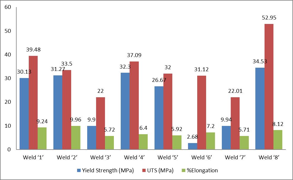
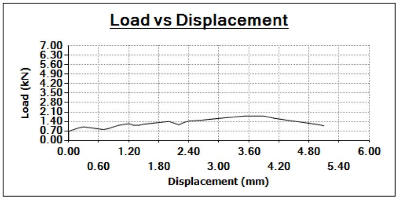
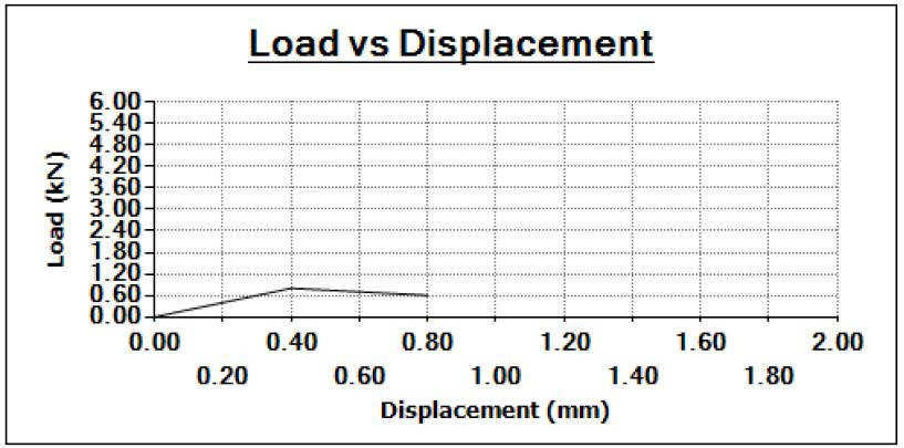
Figure 3.2: Tensile Test specimen after Break.
⮚ FromtheabovedatawecanclearlynoticethatHighestpeakstressis52.95MPaforHexagonalToolpinprofileat 1400rpm,25mm/minweldspeed,1.50 tiltangleonUTM.
Charpyimpacttestwasconductedbyusingimpacttestermachineandtheresultsaregiveninfollowingtable4.3.Theparameter rangeoftoolrotationalspeed1400rpmandweldingspeedof25mm/minandtiltangle1.50 etc.cangivesthehighrangeof
International Research Journal of Engineering and Technology (IRJET) e-ISSN: 2395-0056
Volume: 09 Issue: 12 | Dec 2022 www.irjet.net p-ISSN: 2395-0072
impactvaluethanotherparameters.Theimpactsamplesafterthetestareshowninthefigure. Thereadingobtainedwhile performingthecharpyimpacttestareshownbelowintable4.2:
Table 3.2: Showing Reading Recorded while the charpy impact test
Sample ID Impact Value in (Joules)
Weld‘1’ 3.5
Weld‘2’ 2.0
Weld‘3’ 1.0 Weld‘4’ 2.5
Weld‘5’ 2.0 Weld‘6’ 1.5
Weld‘7’ 1.0 Weld ‘8’ 5.0
Graph 3.2: Graph of charphy Impact Value
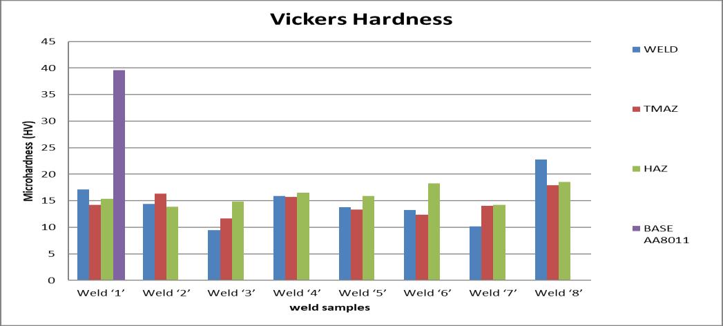
The micro hardness test conducted on Vickers hardness tester to the welded specimen was measured using diamond intenderforvariousweldedspecimenswithvaryingrotationalspeedandtransferspeedwerepreparedandtested.Hardness valuesconsiderundermicroscale.Formthevickershardnesstesttheweldingspeedof25mm/minandthetoolrotationalspeed of1400RPM&tiltangle1.5o isgivengoodrangeofhardnessvalue22.79HV.
Microhardnesstestiscarriedinfourdifferentzones:a.)WeldzoneorNuggetZoneb)TMAZc)HAZzoneandfinallythed) parentmaterialZone.
International Research Journal of Engineering and Technology (IRJET) e-ISSN: 2395-0056
Volume: 09 Issue: 12 | Dec 2022 www.irjet.net p-ISSN: 2395-0072
Table 3.3: Reading is recorded while the micro hardness tester
SAMPLES
SNO:1 SNO:2 SNO:3 SNO:4 SNO:5 SNO:6 SNO:7 SNO:8 (HV 0.1) (HV 0.1) (HV 0.1) (HV 0.1) (HV 0.1) (HV 0.1) (HV 0.1) (HV 0.1)
LOCATION
BASE METAL AA8011 39.6 - - - - - - -
HAZ ZONE 15.33 13.91 14.83 16.52 15.87 18.27 14.22 18.53
TMAZ ZONE 14.25 16.31 11.68 15.75 13.31 12.35 14.08 17.89 WELD ZONE 17.10 14.40 09.46 15.94 13.76 13.26 10.13 22.79
Graph 3.3: Graph micro hadrness test report.3
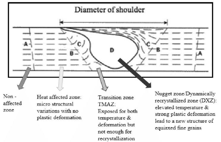
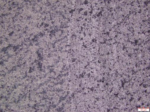
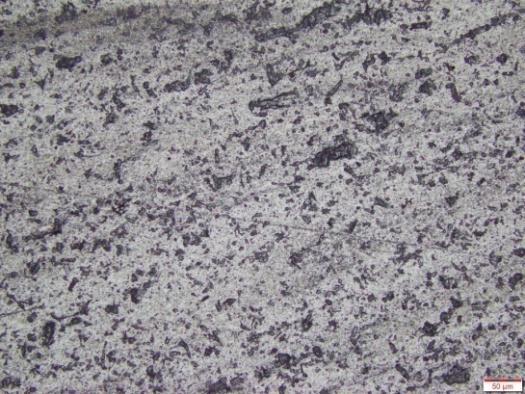
Microstructuretestperformedfromthemicrographs,itcanbeinferredthattheweldsectionofallthejointsinvariably containuniformlycirculated.However,thesizeoftheparticlesisdifferent,anditisfoundtobeinfluencedbythetoolrotation speed.Total8weldedspecimenMicrostructuralstudywascarriedoutindifferentzoneslike:1)NuggetzoneNZ2)TMAZ3) HAZ4)InterfaceZone5)Basemetal
Figure 3.4:FigureshowingthedifferentzonesofFSW.
International Research Journal of Engineering and Technology (IRJET) e-ISSN: 2395-0056
Volume: 09 Issue: 12 | Dec 2022 www.irjet.net p-ISSN: 2395-0072
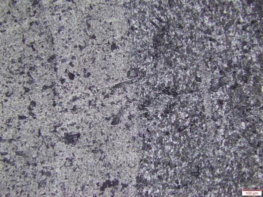
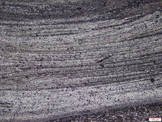
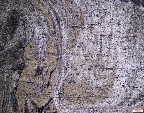
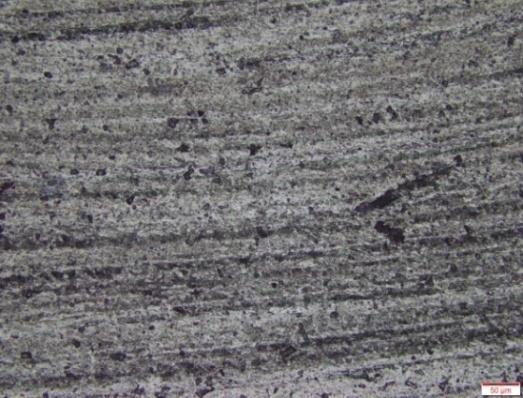
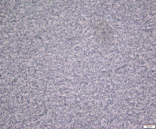
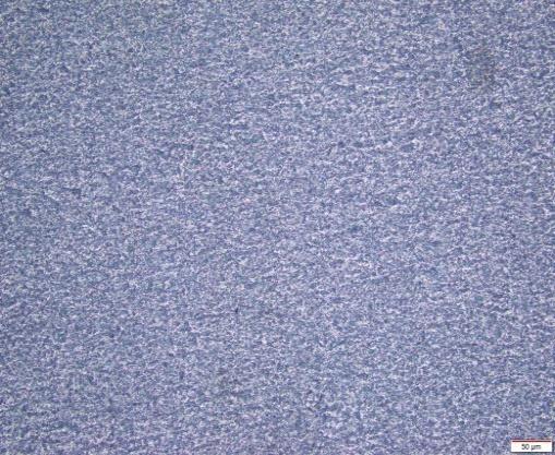
BasemetalAA8011at100X
WELD Sample No.3
BasemetalAA8011at200X
Weldzoneat200X TMAZat200X HAZWeldat200X
WELD Sample No.8
Weldzoneat200X TMAZat200X HAZWeldat200X
Figure 3.5: Microstructure of AA8011 Base metal, welded specimens weld3 & weld8
ThemicrostructureoftheoptimumweldwhichhasthehighestUTSwithintheprocessconditionandthejointaretalk about in this part. The weld efficiency of the optimum joint and the weakest joint is 52.98 MPa and 22.00 MPa, respectively.TheoptimumjointwasobtainedbyusingtheparametersofweldedsampleNo.08.Theweakestjointwas obtainedbyusingtheweldedsampleNo.03bytheadditionofTiO2powderduringweldingbetweentheplates.The amountofthetemperaturegeneratedinFSWusuallydependsonthreeparameters:diameteroftheshoulderandthe combinationoftheweldingspeedsandtiltangle.
International Research Journal of Engineering and Technology (IRJET) e-ISSN: 2395-0056
Volume: 09 Issue: 12 | Dec 2022 www.irjet.net p-ISSN: 2395-0072
The present work investigates the friction stir welding of aluminiumalloysAA8011.Inthistestinitially100×50×6mm dimensionedplatesofAA8011areFrictionStirWeldedwith hexagonal welding tool rotated on the edge of two plates attachedtogetheronamillingmachine.FromtheFSWdata investigatedabovemanyimportantparametershavebeen gatheredregardingtheFrictionStirWeldingbytheaddition ofnanoparticles.FromtheInvestigationdataandfromthe Methodologythevaluesobtainedpractically.Thefollowing datawereconcludedfromtheInvestigation:
From the Tensile Test report the Maximum Peak stress obtained was 52.98MPa on a digitally Automated UTM machine at 1400 rpm and 25mm/min, tilt angle 1.5o weld speed by using hexagonaltoolpin.
[1] R.S. Mishra, Z.Y. Ma, “Friction stir welding and processing”MaterialsScienceandEngineering”Volume50, Issues1-2,31August2005,Pages1-78.
[2]PrashantPrakash,RaviShankarAnandandSanjayKumar Jha. Prediction of weld zone shape with effect of tool pin profileinfrictionstirweldingprocess JournalofMechanical ScienceandTechnology34(1)2020
[3].RavinderReddyBaridula,RamgopalVarmaRamaraju, CheKuMohammadFaizalBinCheKuYahyaandAbdullah BinIbrahim.EffectOfGrooveSizeOnMechanicalProperties andMicrostructuresDueToReinforcementAdditionInFSW DissimilarAlloys.ARPNJournalofEngineeringandApplied SciencesVOL.12,NO.20,OCTOBER2017
From the Tensile Test report the Minimum Peak stress obtained was 22.00MPa on a digitally Automated UTM machine at 1120rpm and 35mm/min,tiltangle1o weldusingHexagonaltool pin.
[4]. Yaswanth Rao Yatapu, Baridula Ravinder Reddy, RamgopalVarmaRamaraju,MohammadFaizalBinCheKu, and Abdullah Bin Ibrahim, PREDICTION OF TEMPERATURES DURING FRICTION STIR WELDING OF AA6061 ALUMINIUM ALLOY USING HYPERWORKS (ARPN JournalofEngineeringandAppliedSciences)VOL.11,NO. 18,SEPTEMBER2016
From Impact Test report the maximum impact value obtained was 5.0 joules on a digitally Automated impact tester machine at weld specimen.08 and 1400rpm and 25 mm/min, tilt angle1.5o speedusingHexagonaltoolpin.
And minimum impact values obtained were 1.0 joulesonadigitallyautomatedimpacttestmachine at weld3,weld7duetosamevalues.
FromMicrohardnessTestisconductedattwopoint in each location and it is observed that Maximum Hardnessisobtainedtospecimenno:08thatisFS welded at 1400rpm; 25 mm/min weld speed and 1.5o tilt angle. The obtained hardness is at HAZ@18.53HV, at TMAZ@17.89HV, at NZ@22.79HV.LowestHardnessisobtainedatWeld specimen no:03 which is welded at 1120rpm ,35mm/min weld speed and 1o tilt angle. The obtainedHardnessisatNZ@09.6HV.
[5]. Ravinder Reddy Baridula1*, CheKuMohammad FaizalBin Yahya1, Ramgopal Varma Ramaraju2 and Abdullah Bin Ibrahim1,EffectofWeldingSpeedonMicrostructurea nd Mechanical Properties due to The Deposition of Reinforcements on Friction Stir Welded Dissimilar Aluminium Alloys[AA2014-AA7075], MATEC Web of Conferences 135, 00039 (2017) DOI: 10.1051/matecconf/201713500039
[6]. Ravinder Reddy Baridula, Abdullah Bin Ibrahim and MohammadFaizalBinCheKu,EffectofRotationalspeedon mechanical properties and microstructure due to the additionofreinforcementsonfrictionstirweldeddissimilar aluminum alloys [AA5052 –AA6063], The National Conference for Postgraduate Research 2016, Universiti MalaysiaPahang,
Microstructure resultsshow thatbetter mixing of materialinthestirzonebyusinghexagonalpin.The grainsizewasfoundtobefineduetotheadditionof nanoparticlesinthestirzone.Microstructureresult also showed best mixing of material in fourth chapter4.4microstructure.
Theresultsalsoshowthatprocessparametersand additionofnanoparticlesinfluencethestrengthof theweldedjoints.
[7]. Khethavath Venkat, study of mechanical and metallurgical propertiesoffriction stir weldedaluminium alloys AA2014 and AA6082 by addition the TiO2 nanoparticlesanditssimulationanalysis,IRJET,7volume11 issues2021.
[8].RavinderReddyBaridula1RamgopalVarmaRamaraju2 AbdullahBinIbrahim1MohammadFaizalBinCheKuEffect ofNanoParticleDepositiononMechanicalProperties
of Friction Stir Welded Dissimilar Aluminium Alloys by Taguchi Technique Trans Indian Inst Met (2017) 70(4):1005–1017
International Research Journal of Engineering and Technology (IRJET) e-ISSN: 2395-0056
Volume: 09 Issue: 12 | Dec 2022 www.irjet.net p-ISSN: 2395-0072
[9].SRavikumar,VSeshagiriRaoandRVPranesh,Effectof ProcessParametersonMechanicalPropertiesofFrictionStir Welded Dissimilar Materials between AA6061-T651 and AA7075-T651 Alloys, International Journal of Advanced MechanicalEngineering,2014,4(1),101-114.
[10]. A Pradeep and S Muthukumaran, An Analysis to Optimize the Process Parameters of Friction Stir Welded LowAlloySteelPlates,InternationalJournalofEngineering, ScienceandTechnology,2013,5(3),25-35.
[11].Dr.Ch.S.NagaPrasad,ExperimentalInvestigationand Finite Element Analysis of Fristion Stir Welding of Two DisimilarMaterias,IJRMETVol.7,IssuE2,May-ocT2017.
[12]. Takashi Nakamura, Toshiyuki Obikawa, Eitaro Yukutake, Satoru Ueda, Itaru Nishizaki, Tool Temperature and Process Modeling of Friction Stir Welding, Modern MechanicalEngineering,2018,8,78-94.
[13]. Dr.M.Chandra Sekhar Reddy, B.Eswaraiah,Anthati Naveen Kumar,Experimental Investigations and finite element analysis of friction stir welding of various aluminiumalloys,IJERT:2278-0181,2017.
[14]. ArunKumarKadian,GautamPuri,SumanDas,Pankaj Biswas,Effectoftoolgeometryandprocessparameterson thematerialflowoffrictionstirwelding,5thInternational& 26th All India Manufacturing Technology, Design and ResearchConference(AIMTDR2014)December12th–14th, 2014,IITGuwahati.
( Mr. BEGARI NAGESH ) Student of M.Tech in Department of Mechanical Engineering, VJITHyderabad,Telangana,India,

( Mr. Khethavath venkat) AssistantProfessorinDepartment ofMechanicalEngineering,GNITCHyderabad,Telangana,India