International Research Journal of Engineering and Technology (IRJET) e-ISSN: 2395-0056

Volume: 09 Issue: 12 | Dec 2022 www.irjet.net p-ISSN: 2395-0072
International Research Journal of Engineering and Technology (IRJET) e-ISSN: 2395-0056
Volume: 09 Issue: 12 | Dec 2022 www.irjet.net p-ISSN: 2395-0072
Kanishk Kundu1
1 Dhirubhai Ambani International School, Mumbai, India. 400098 ***
Abstract - A space elevator is a concept that is being pursued by many researchers around the globe. One of the space elevator's most critical components is the tensile loadbearing cables, which will require immense strength. This paper explores three different materials for space elevator applications in a wire rope design as load-bearing elements of a space elevator. Finite-Element Method (FEM) is used to numerically model the stress-strain behavior of wire ropes of Steel, Titanium, and Carbon Nanotubes under the tensile loading conditions of a space elevator. It was found that the strength-to-weight ratio is the highest for Carbon Nanotubes; hence, it was the only material suitable for such an application. Such a study can be helpful for designers of future space elevators once the manufacturing capabilities of Carbon Nanotubes scale up to meet such demands.
Key Words: Space Elevator, Finite Element Method, CarbonNanotubes
Theeraofspaceexplorationhasneverbeenasexcitingas today and satellites are being used in almost every field now. With the rising number of satellites and their applications, the process of improving the efficiency of launching a satellite has become an area of interest for a lotofresearch.Aspaceelevatorisonesuchproposedidea that can revolutionize the placement of satellites in lower earthorbitswithasignificantcostreduction.
Due to the rising cost of launching space shuttles, the requirement of a space elevator is well justified [1]. A detailedreviewoftheentireconceptofthespaceelevator anditscomponentsisdocumentedbyEdwardsinhisbook [2].Thisapplicationattractedresearchers’interestwhenJ Pearson[3]solvedtheproblemofbucklingbyproposinga design of a cable entirely based on tension which was considered in most of the future research in this domain. Space elevators in concept will use a long combination of cables with one end on earth and the other one tied with counter weight in the lower earth orbit or space. The center of mass of such a system would also be in space giventhecounterweightlocation.Inthisarrangement,the structure would remain rigid due to the gravity and centrifugal force acting in the opposite directions. Due to these opposite forces, the structure would be under immense tensile load as opposed to the compressive load which was thought initially during the conception days of thespaceelevator.Apartfromstrength,thespaceelevator cable must also be highly conductive as there will be
friction produced due to the relative motion of the elevatoron thecable,andhenceheat will be generated in high amounts. In space with no ambient atmosphere to dissipate heat, the temperature of the cable may reach very high in a short period and may lead to catastrophic damageorfailure.Moststructural applicationswill utilize twisted wire ropes in place of rods for better flexibility andstrength-to-weightratio.
Edwards[4]gaveacomprehensivedesignoftheelevators considering different issues like tapering of the cable, energy sources, and collisions with meteors or space debris. In recent years, the focus has been mostly on gauging the strength of the rope by identifying novel materialslikecarbonnanotubes[5].
In this work, an ultimate tensile test of a twisted cable is simulatedfordifferentmaterialstoevaluatethefeasibility of a space elevator. A numerical model is created with a tensileloadappliedononeendofthecablewhilekeeping the other end fixed. Finite element method is used to analyzetheeffectoftensileloadingonVon-misesstressin atwistedcabledesign.Inthisway,theworkingconditions of a space elevator cable are simulated using the learning edition of Abaqus software. Three materials were taken into consideration for this study: Steel (AISI 430), Titanium(Ti-6Al-4V),andCarbonNanotubes.
A uniform tensile strength (UTS) test is one of the most reliable and widespread methods of evaluating the mechanical properties of a material. In a UTS test, the specimenispulledindifferentdirectionstoimparttension inthespecimenandmeasureelongationaswedoittillthe specimen breaks apart. The output of the test is a stressstrain curve that governs the behavior of the material under tensile loading. The tensile strength is an intensive property and hence can be evaluated with small specimens as well as tensile tests. Since it is timeconsumingandexpensivetoconductaphysicaltensiletest of different materials, numerical simulations are performedtogettheresults.
Threematerialsaretakenintoconsiderationforthesame design and load calculations are made. Low carbon steel was taken as it’s a low-cost structural material widely usedwithlargemanufacturingfacilitiesallovertheworld. Titanium was the second choice as the tensile strength was one of the highest in common materials. The third
International Research Journal of Engineering and Technology (IRJET) e-ISSN: 2395-0056
Volume: 09 Issue: 12 | Dec 2022 www.irjet.net p-ISSN: 2395-0072
materialiscarbonnanotubeswhichhavetheoreticallythe higheststrengthoftheexistingmaterials.Thetablebelow givesthevaluesofpropertiesusedinthesimulations.
Aspace elevatorsystemcan utilize multipletwistedcable systemstoreducetheloadonasinglemember.Onesingle twisted cable is analyzed in this work to estimate its tensilestrength.
The specimen for the simulation is taken to be composed ofahomogeneousmaterialwithauniformcross-section.It is also assumed that a pure unidirectional tensile load is acting on the specimen and the process is taken to be isothermal.
Inauniformtensiletest,wecandefinethefollowingas: ○ Linearstrain ○ Logarithmic(“true”)strain ○ Nominal(“engineering”)stress
stress (out of plane stress due to uniaxial loading)
Areaofperipheralwire =numberofwires
Areaofmiddlecircularwire
Boundaryconditionsandloading: ○ Encapsulated boundary condition on left side
U1=U2=U3=UR1=UR2=UR3 =0 ○
Uni-axial tensile loading on right side (Zdirection)
U3=Strain/Displacement/Force
Thesimplestequationtocorrelatetrueflowstress( )and true plastic strain ( ) is given by Holloman [6] using a strength coefficient ( ) and a strain-hardening exponent ( ) ( )
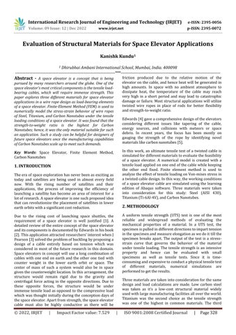
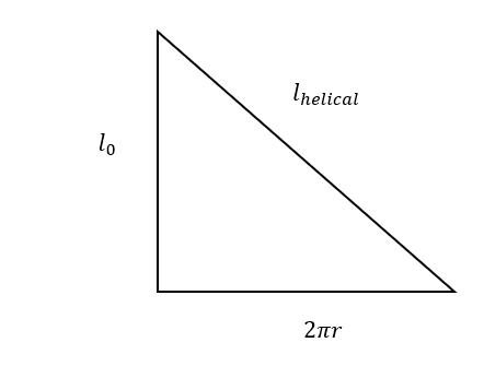
The cos component will become compressive and therefore, compressive forces will act over whole central sectionwhichishelicalinshape.
Wecancalculatethecompressiveforceasthefollowing: ( ) ( √ )
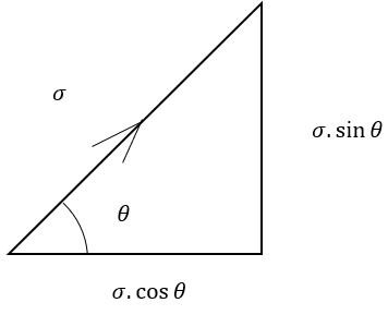
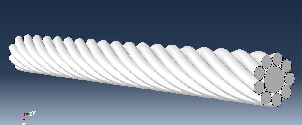
Asseeninfigure1,thespecimenisa twistedcablewith a straight core. The dimensions of the cable are mentioned infigure1(b).
2395-0056
Figure 1 :AnimageofatwistedcableusedforFEM simulations
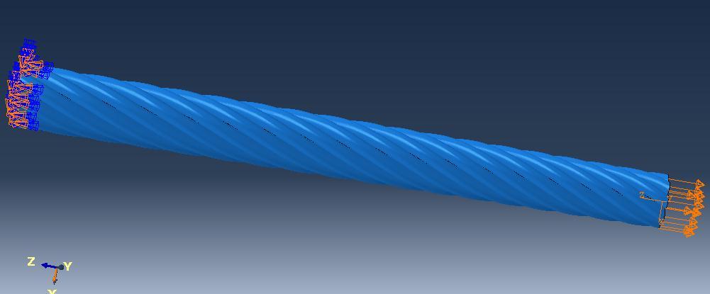
Figure 3:Modelwithfixboundaryconditiononleftside andaxialloadingalongthelength(rightside)ofthewire forFEMsimulations
A fixed boundary-based condition on the left side and a free uniaxial loading along the length is represented in figure3asaresultoftheFEMsimulations.
Figure 2:Modelcross-sectionwithdimensions
Figure 1 and figure 2 represent the outlook offering twisted wire to be used for finite element modeling simulation part a represents the complete structure of a twisted wire cable and Part B represents the crosssectionaldimensions.
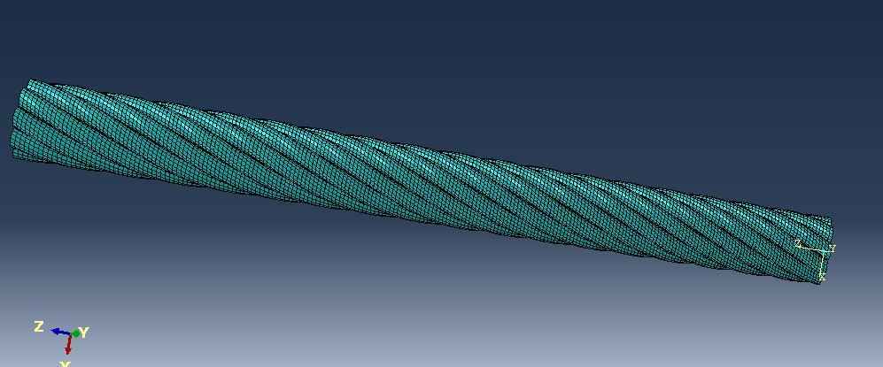
Figure 4:Modelwith3DmeshingandC3D8R(An8-node linearbrick,reducedintegration,hourglasscontrol) elementtype
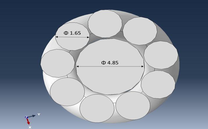
Figure 4 represents the 3-dimensional meshing of the twisted rope with general purpose linear brick element (C3D8R).
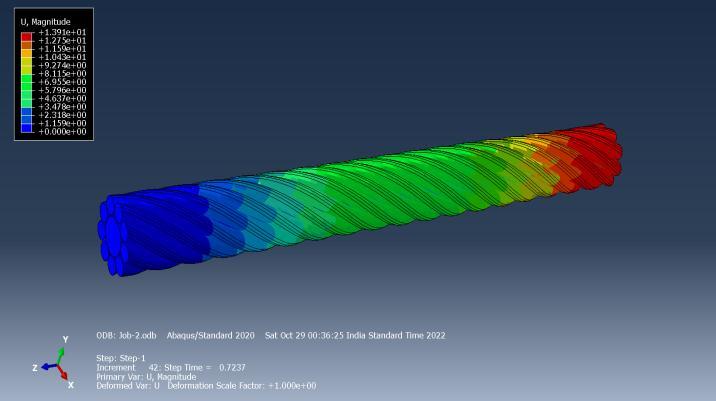
The color-coded FEM simulation results of the displacement of the twisted rope are represented in Figure 5. It can be seen that the displacement decreases along the length of the wire. Maximum displacement is observedontheright-handsidewheretheloadisapplied, andzerodisplacementisobtainedonthefixedend.
International Research Journal of Engineering and Technology (IRJET) e-ISSN: 2395-0056
Volume: 09 Issue: 12 | Dec 2022 www.irjet.net p-ISSN: 2395-0072
Figure 5:Displacementofthetwistedrope
Figure 6representsthedisplacement trendcaused by the wire along the length. As the distance along the wire increases, its displacement per element decreases. This is because the wire displacement depends on the strain, which is a function of the length or distance along the wire.Ifwerecallthemathematicalexpressionforthetrue strain of a material, it can be seen that the strain (and hencedisplacement)isinverselyproportionaltotheinitial length.
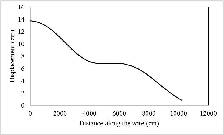
Figure 7:Vonmisesstressesofthetwistedrope
Figure 6:Displacementoftwistedwireasafunctionofit distance
Figure 7 and 8 represent the Von Mises stresses and the pressure on the twisted rope. Von mises is maximum in central rope, whereas pressure is maximum in peripheral rope.
Figure 9 represents the stress vs strain behavior of lowcarbonsteelforacircularandawireropecase.Hereitcan be seen that the slope in the elastic region (i.e., young’s modulus) is higher in the case of twisted wire rope. Although there is little difference between the yield strength and tensile strength in both cases, the yield ultimate tensile strength is almost double for the case of twistedwirestrength.
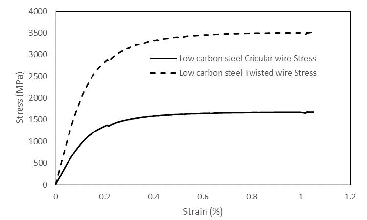
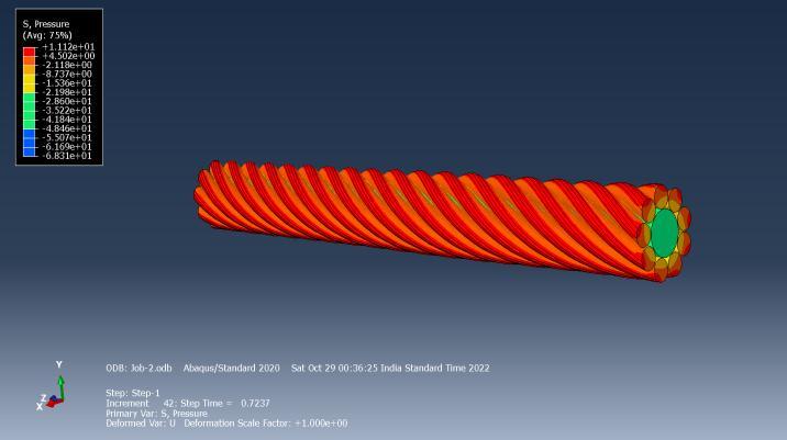
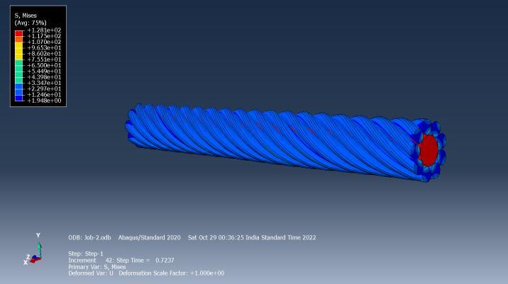
Figure 9:Stress-strainplotoflowcarbonsteelcircular wireandtwistedwirestress
International Research Journal of Engineering and Technology (IRJET) e-ISSN: 2395-0056
Volume: 09 Issue: 12 | Dec 2022 www.irjet.net p-ISSN: 2395-0072
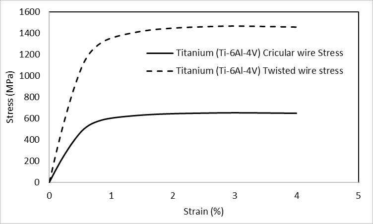
Figure 10 represents the stress vs strain behavior of Ti6Al4V alloy for a circular and twisted wire case. Here also, just like steel, it can be seen that young’s modulus is higherinthecaseoftwistedwire.Despitelittledifference between the yield and tensile strength for circular and twisted wire stress cases, the yield strength (and also the tensile strength) of the twisted wire case is three times thatofthecircularwirecounterpart.
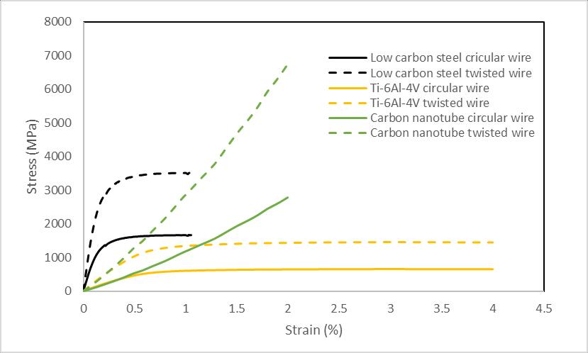
behaviorforthetwistedwirecaseisalwaysonthehigher sideirrespectiveofthechoiceofmaterialbutaddingto it, carbon nanotube exhibits the highest strength as comparedtotheotherchoices.Onthe other hand, Ti-6Al4Vexhibitsthebestductilitybutthiscomeswithapenalty on its strength. Low carbon steel is quite a balance between both strength and ductility as it exhibits an optimal combination of both better tensile strength and reasonableductilitytillfracture.
The maximum stress that was experienced without any reduction in the cross-section of the specimen was with carbonnanotubes.
Figure 10:Stress-strainplotoflowcarbonsteelcircular wireandtwistedwirestress
So, as far as metallic alloys are concerned, twisted configuration exhibits better tensile properties than circularcase.
Figure 11 also shows the trend commensurate with the caseofmetallicalloys.hereaswellthe stressisalwayson thehighersideforthetwistedwiresystemascomparedto the circular wire counterpart. So, all the above figures point to results that despite the choice of material the tensile property is much better for the twisted wire configuration.
Figure 12:Stress-straincurveforthecaseofcircularand twistedwirestressforallthechoicesofmaterial
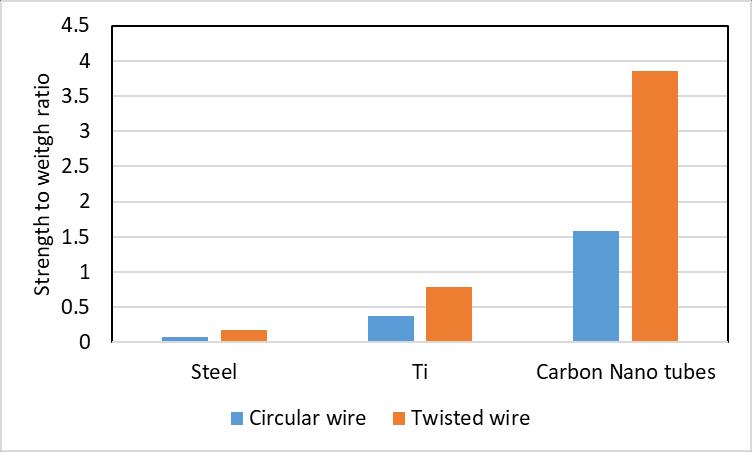
Finger 13 is a comparative measure of the strength-toweight ratio for the circular and twisted wire configuration for steel titanium alloy and carbon nanotube. Steel exhibits the poorest strength-to-weight ratio among all the 3 cases for both circular and wire configurations. Carbon nanotube stands to be the best withthehigheststrength-to-weightratioofapproximately 3.8(which is the highest among all the cases). Another important observationis thatirrespective of the choice of material here as well the strength-to-weight ratio for the caseofthetwistedwiresystemstandstobebetterthana circularwireconfiguration.
Figure 11:Stress-straincurveforthecarbonnanotubes forthecaseofcircularandtwistedwirestress
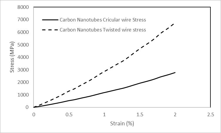
Figure 12 is a composite view of the tensile behavior of low-carbon steel, Ti-6Al-4V alloy, and the carbon nanotube. While it is well understood that the tensile
International Research Journal of Engineering and Technology (IRJET) e-ISSN: 2395-0056
Volume: 09 Issue: 12 | Dec 2022 www.irjet.net p-ISSN: 2395-0072
The author would like to express their gratitude towards Dr. Anandita Singh (Safran Aircraft Engines) for her valuableinputs,guidanceandcompletementorshipduring theentirecourseoftheproject.
[1] Swan,CathyW.,andPeterA.Swan."Whyweneed a space elevator?" Space Policy 22.2 (2006): 8691.
Figure 13:Strengthtoweightratioofcircularandtwisted wireforsteel,Tialloyandcarbonnanotube
A space elevator is a fascinating concept requiring considerableresearchandengineeringeffort.Thisworkis one such contribution to these efforts where the loadbearing structures of the space elevator were analyzed. A comparison was made between constant cross-section cables are wire ropes to evaluate the higher load-bearing option of these. Additionally, three different materials were considered for the load-bearing analysis: Steel, Titanium, and Carbon Nanotubes. Finite-element analysis was performed using the Abaqus software for evaluating thetensilefailureloadofrodsandtwistedwireropes.The stress-strain curve and the strength-to-weight ratio were calculated for all the cases and materials, and relevant analysiswasperformed.
It was observed that the maximum stress reached in twisted wire ropes of low-carbon steel was more than twice that of the circular cross-section specimen. Similar observations were made for Carbon Nanotubes and Titanium as well. The strength-to-weight for low carbon steel was lower than 0.3; for Titanium, it was more than double with a value of around 0.75. The maximum strength-to-weight was obtained for Carbon Nanotubes withatremendousvalueofmorethan3.75.Thisindicates that Carbon nanotubes are the most suitable for Space Elevator load-bearing structures among the existing materials. However, there is yet to be an existing prototype of a rope long enough to be used in structural applicationsusing exoticmaterialslikecarbon nanotubes. Therefore, any development in the field of structural materialsforspaceelevatorswillrequirethedevelopment of manufacturing capabilities for carbon nanotubes at a large scale. The present work can help engineer the loadbearing elements when the capability of manufacturing CarbonNanotubesisdevelopedtolargeextents.
[2] Edwards, Bradley C., and Eric A. Westling. The spaceelevator.BCEdwards,2003.
[3] Pearson J 1975 The orbital tower: a spacecraft launcher using the Earth’s rotational energy Acta Astronautica2785-799.
[4] Edwards,BradleyC. "Design anddeploymentofa space elevator." Acta Astronautica 47.10 (2000): 735-744.
[5] Pugno, Nicola M. "On the strength of the carbon nanotube-based space elevator cable: from nanoto mega-mechanics." arXiv preprint condmat/0601668(2006).
[6] Bowen, A. W., and P. G. Partridge. "Limitations of the Hollomon strain-hardening equation." Journal ofPhysicsD:AppliedPhysics7.7(1974):969.