International Research Journal of Engineering and Technology (IRJET) e-ISSN: 2395-0056

Volume: 09 Issue: 12 | Dec 2022 www.irjet.net p-ISSN: 2395-0072
International Research Journal of Engineering and Technology (IRJET) e-ISSN: 2395-0056
Volume: 09 Issue: 12 | Dec 2022 www.irjet.net p-ISSN: 2395-0072
1Department of Computer and Electrical Engineering 2University of Energy and Natural Resources- Sunyani, Ghana ***
Abstract - Induction motors account for approximately 70% of all electric motors used for industrial purposes as a result of their versatility, robustness, reliability, low cost and high efficiency. However, induction motors have an undesirable characteristic of drawing high current during start-up. This necessitates special starting methods to monitor and control the starting current. The high starting current leads to issues such as a dip in the power system voltage which affects other systems and equipment connected to the affected power system. Various starting methods have been developed to overcome this problem. Six of these methods have been discussed and analyzed in this paper: Direct- on-line (DOL), Star-Delta, Autotransformer, Capacitor Starting and Soft Starting. A comparison of their current, torque, and speed are analyzed. Results obtain shows that an absolute conclusion cannot be made outright about one starting method being better that the other because there is a trade off in all these methods. Based on the analysis, a new starting method is proposed, which may eliminate the major deficiencies of the existing methods.
Key Words: Current, Induction motor, Soft Starting, Speed, torque.
LECTRIC MOTOR accounts for large percentage of the generated electrical energy consumed. For instance, in the European Union, electric motors account for as much as 65%–70% of the consumed electrical energy [1]. Most of these motors are 3-phase squirrel-cage induction motors because of their reliability, robustness and relatively low cost [2]. In spite of their usefulness in industry,startinga3-phaseinductionmotorisofimmense concern to the stability of a power grid. A 3-phase induction motor is theoretically self-stating, yet without any specialized starting mechanism, the current drawn at start can reach as high as 5-8 times the motor’s rated current [3, 4]. Such large start current can destabilize the grid causing dip in the grid voltage and have a serious impact on the normal operation of other adjacent equipment such as lights, sensitive equipment etc. The start current may also have devastating effects on the stator winding and rotor bar, damaging the winding insulation [5, 6]. For these reasons, specialized starting methods have been developed The 3-phase squirrel-cage induction motor (IM) may be started by supplying full voltageorreducedvoltage[6].DirectOn-Line(DOL),Star-
Delta and Autotransformer starting methods are commonly used in fixed speed applications as traditional electromechanical starters. Each starting method has its ownmeritsanddemeritswhichmakeonestartingmethod preferredovertheother.Thebasisforselectionmustbea thorough understanding of the power system constraints, the load to be accelerated and the overall cost of the equipment[3].Thestartingcurrentofthevariousstarting methods is investigated in this paper using simulation models that aid in understanding the starting characteristics.
The starting method for a 3-phase induction motor is not to provide a high starting torque but rather reduce heavy starting currents and prevent motor from overheating.Thereareseveralgeneralmethodsdeveloped toaddressparticularinductionmotorstartingproblemsin terms of the motor size and the stability of the connected network.
In considering the factors taken into account in the designofthestartingmethods,itisrealizedthat,trade-offs of certain factors may haveto be introduced fora starting method to suite a particular application [7]. The various starting methods can be broadly categorized into conventional motor starters and electronic drives [8]. Conventional motor starters are often used in fixed speed applications and includes direct on-line, star-delta, shunt capacitor and autotransformer starter. DOL starter is the simplest and the most inexpensive of all the starting methodswithaverylargestartingcurrent,normally6to8 timestheratedcurrent[5].Thestartingtorqueislikelyto be 0.75 to 2 times the full load torque [5]. DOL starter is used only for motors with a rating of less than 5KW [8].Inductionmotorsthataresetupforstardelta starter are built so that the leads from each end of each phase groupareeasilyaccessible.Inthiswaythemotorleadsare initially connected in star and once the motor speed reaches about 70% of the rated speed, the power supply connectiontothemotorischangedtoadeltathusgivingit a full voltage. A major problem with the Star-Delta starter is the spike in current that occurs during transition from star to delta configuration. A closed transition starter is developed which employs series resistors to eliminate the current spike experienced by the open transition starter. However, the closed transition starter results in reduced torqueanditdoesnotprovidespeedcontrol[9].
International Research Journal of Engineering and Technology (IRJET) e-ISSN: 2395-0056
Volume: 09 Issue: 12 | Dec 2022 www.irjet.net p-ISSN: 2395-0072
The autotransformer can be looked as an improvement of the star-delta starter. It uses tap changes to reduce the voltage available to the induction motor during start. This will proportionally reduce the starting current and the torque[5,8].Theadvantageoftheautotransformerliesin the users’ ability to select different tap values. With this, theusermaychangethetaptosuitaparticularapplication. However, the cost of installing an autotransformer is expensive compared to the other conventional motor starters. The induction motor requires large inductive current to operate which lags the applied voltage. Shunt capacitor starter acts to supply current that leads the voltage hence reducing the amount of reactive power required to be drawn from the power system. The shunt capacitance may be left connected if they are properly ratedsoastoprovidepowerfactorcorrectionorremoved asthemotorapproachesratedspeed.
Electronic drives allow the stator input voltage to be gradually increase and hence the starting current. Soft starters may employ semiconductors, to reduce the initial start voltage of the induction motor resulting in lower motor torque. During the starting process, the soft starter progressively increases the motor voltage so that the motor generate enough power to accelerate the load to rated speed. The soft starter gradually increases the voltage from a pre-set level, as low as 0V, to the rated voltage. This causes very smooth start-up. However, this resultsinhigherharmonicsbeinginjectedintothesystem. The current limiting technique senses the current at the motor so that the firing angle can be controlled proportionately [10]. The soft starter adds significant flexibilityinoperationandinteroperability,duetothefact that it is more sensitive to the mechanical load characteristics.Thisalsoresultsinlowermaintenancecost and increased lifetime of the mechanical load, and can result in improved energy efficiency. However, the tradeoff is the increased operational complexity, and soft startersaregenerallyexpensivedevices[7,8].
The paper is organized as follows: Section II describes the system modelling and its parameters. Section III highlights a briefdescriptionofthevarious motorstarters using simulations and in Section IV, a number of case studies and discussions are outlined. and the conclusions aresummarizedinSectionV.
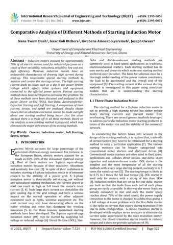
The paper models three system primitives; three phase squirrel-cage induction motor, induction motor starting controlcircuitandagridconnectedbusbarsysteminFig.1. The IM is modeled with ETAP® (Electrical Transient Analyzer Program) as a 373kW 4kV dynamic machine using the predefined circuit model MV500HP2P from ETAP® library in Fig. 2. Using a NEMA design type B, the model data describes the specific 373kW motor intended
foraccelerationinthisstudy.TheparametersofthethreephaseIMisfoundinTable1.
Model Data Rs(Ω) Xs(Ω) Xm(Ω) Xrlr(Ω) Xrfl(Ω) Rrlr(Ω) Rrfl(Ω) 3.832 10.29 365.2 9.3 11.67 1.23 1.52
Name Plate Data
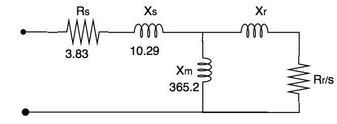
The connected load is modeled as a simple fan with the characteristic torque equation expressed in percentage as in(1).ThemotorcharacteristicsisshowninFig.3
LoadTorque=10–91w+321w2-147w3 (1) wherewisavariable.
a b c
Busbar
Controller
KVA FLA %PF %Eff %NLA Inertia kgm2 Torque ft-lb 434 62.7 92.08 93.22 26.63 0.793 1481.9 Induction Motor
Fig.1. Systemmodel
Fig.2.Equivalentcircuitofthreephaseinduction motor

International Research Journal of Engineering and Technology (IRJET) e-ISSN: 2395-0056
Volume: 09 Issue: 12 | Dec 2022 www.irjet.net p-ISSN: 2395-0072
simulated with automation studio. Data from ETAP is exportedtoMATLABtoplotsthegraphs.Graphsofcurrent, torque, speed with time are shown with all the various starting methods. All the other methods are compared to DOLmethod.
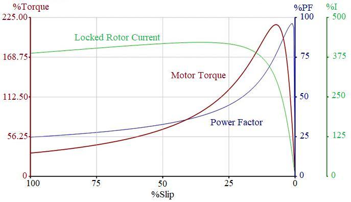
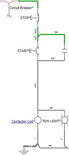
DOL is implemented with a direct connection of the motor terminals to the power source through a single contactor in fig 4. The motor draws a very high inrush current However, as the motor accelerates, the current begins to drop, but until the motor is at a high speed, typicallyabout85%ofsynchronousspeed.
The load torque is defined such that it lies distinctly below the available machine torque so that under normal operatingconditions,itwillaccelerate.Thecouplingofthe fantothemotorisachievedbymeansofasimplecoupling gear.Themotormustnotonlydevelopadequatetorqueto overcomethefanload,butitmustalsohaveexcesstorque toovercometheinertiaofthefanandaccelerateittospeed within a desired amount of time. The coupling arrangementofthefaninertia(WR),couplinggearandthe motorinertiaismodeledasin(2). 2 22f msfs m
n WRWR n (2) where:
WRms :Inertiaoffanloadreferredtomotorspeed.
WRfs: Inertiaoffanloadplusdrives nf :Speedoffan. nm:Speedofmotor ETAPusesthemotorinertia(H)togeneratecorresponding dataforfaninertiainordertostudytheaccelerationwhen thevalueofHismanuallyinsertedasshowninTable.2.
TABLE 2: MOTORCOUPLINGCHARACTERISTICS
Motor Coupling Load Total
RPM 1800 1800 1800 1800 WR2 118 59.02 295.1 472.1 H 0.198 0.099 0.496 0.793
Five starting methods are implemented with ETAP but the individual control circuits are all designed and
The motor terminals are connected in the star pattern initiallyreducesthelinevoltageby57.7%andthenthefull line voltage is applied in delta connection after the motor achieve 85% of the rated speed. The connection is shown inFig.5.
The connection of this starter is demonstrated in fig.6. The motor is first started in a single phase mode with the help of a properly selected phase balancer capacitor and then switched to normal three phase operation once its speedreaches70%oftheratedspeed
The motor is connected to the secondary side of the autotransformerwhilestartingasinFig.7.Thetapsonthe autotransformer limit the voltage applied to the motor to 50%, of the nominal voltage and the line current is less thanthemotorratedcurrentduringstarting.
International Research Journal of Engineering and Technology (IRJET) e-ISSN: 2395-0056
Volume: 09 Issue: 12 | Dec 2022 www.irjet.net p-ISSN: 2395-0072
Voltagerampingandlimitedcurrentstartingisusedforthe electronic soft starting. Pulse width modulation (PWM) is employed to trigger pulses to control the firing angle in ordertoachievethedesiredvoltagecontrol. Thevariation of the firing angle limits the line voltage supplied to the motor terminals. Fig.8 depicts Allen-Bradley soft starter connection.
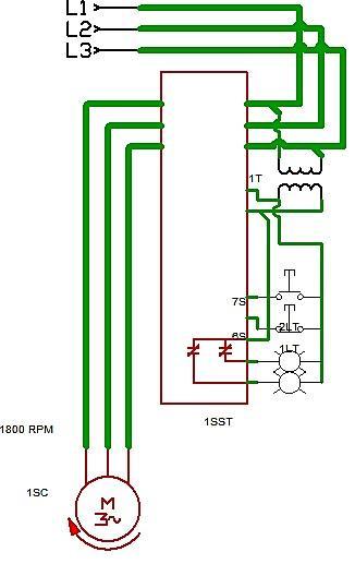
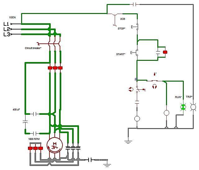
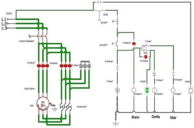
Fig.5 StarDeltaStartMethod
Fig.6 CapacitorStartMethod
Fig.8Allen-Bradleysoftstarter
Theresultinggraphsofcurrentagainsttimeforthefive starting methods are given in Fig. 9. The starting current ofstardeltastarterisapproximately175%ofthefullload current (FLC) as compared to DOL which is about 500% In the case of autotransformer start, the current starts with about 125% of FLC. The current increases smoothly to 310% of FLC as the speed increases before the autotransformer is taken out of the circuit. Using the capacitor method, the current rises to approximately 380% of FLC. However, in the soft-start method, the current rises gently from 30% to 420% of the FLC when the voltage is ramped from 10% to 100% using a current limit of 750%. The current drops to the rated full load current after 18 seconds. Star delta and autotransformer startershavehighinrushcurrentduringtheswitchover.
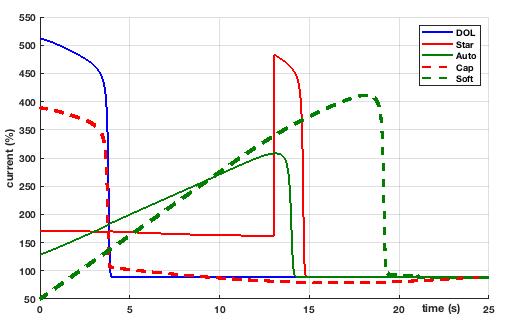
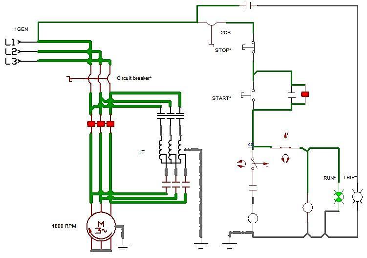
Fig.9.Startingcurrents
Fig.7AutotransformerstartMethod
International Research Journal of Engineering and Technology (IRJET) e-ISSN: 2395-0056
Volume: 09 Issue: 12 | Dec 2022 www.irjet.net p-ISSN: 2395-0072
disturbing switch-over transients. Also, increasing the firing angle of the soft starter reduces thestartingcurrent but increases the motor acceleration time. The results show that there is trade-off in all the different stating methodsofIM
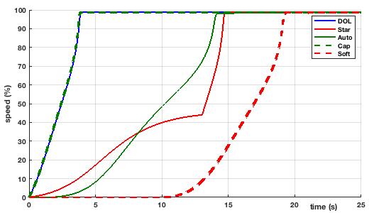
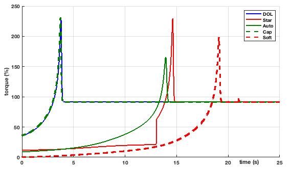
Fig. 10 shows graphs of starting torque with time for all the starting methods. Both Capacitor and DOL starting methods have similar torque characteristics. The starting torqueofstardeltais30%oftheratedtorque.Thetorque ofDOLandstardeltarisessharplytothemaximumtorque with in 4s and 14s respectively. The corresponding starting torque for autotransformer method is approximately 10% of the rated torque; this increases graduallyto165%at13softhefullloadtorquewherethe autotransformer is taken out of circuit. The resulting graphsofspeedwithtimeforallthefivestartingmethods are shown in Fig.11 The speed of DOL and capacitor start reachestheratedspeedwithin3swhileittakesabout18s for electronic softer starter to reach the rate speed. Star delta starter and autotransformer starters takes almost thesametimetoreachtheratedspeed
The starting characteristics of different starting methods for IM have been studied. Computer simulations provideflexiblemeanstoaidinthedecisionmakingofthe beststartingmethodtoapplyforspecificapplications.The simulation results indicate that, an absolute conclusion cannot be made outright about one starting method being better than the other unless their frame of comparison is justified. The star-delta, autotransformer and soft starter reduces the starting current significantly however the trade-offamongthesemethodsisthereductioninstarting torque. The star-delta and autotransformer can also have
It is observed that, all the starting methods try to bringthemotoruptotheratedspeed.Thedifferencein shape of the speed curve is as a result of, the various startingmethodsdrawingdifferentamountofcurrentto bring the motor up to speed. It is projected that, if an external means isused tobringthe motor’sspeed toat least 60% of the rated speed before connecting to the power source; the amps drawn will reduce proportionally.Thisknowledgecanbeimplementedasa torque assisted method where smaller motor can be used to turn a higher rated motor at no load to about 60% of the motor’s rated speed. The smaller motor is then decoupled from the set up and the higher rated motorconnectedtothepowersource.Thismethodmay eliminatethemajordifferencesinthediscussedstarting methods. Further work should be carried out on the proposedmethodoftoachieveanefficientdesign.
[1] A. Almeida, F. Ferreira, J. Fong, and P. Fonseaca, "EuP Lot 11 motors, ecodesign assessment of energy using products," University of Coimbra, Brussels, Germany, 2008.
[2] Almeida, P. Fonseca, F. Ferreira, F. Guisse, A.Diop, A. Previ,S.Russo,,"Improvingthepenetrationofenergy - efficient motors and drives," University of Coimbra, Brussels,Germany,,2000
[3] S.K. Kim and T.K. Kim, "A Novel Hybrid Sequential startcontrolsystemforlargeinductiveloads," Journal of Electrical Engineering & Technology, vol. 10, no. 1, pp.388-394,201
[4] W.J.Horvath,"Concepts,Configurations&Benerfitsof MotorsStartingandOperationwithMVACAdjustable Speed Drives," IEEE Cement Industry Techinical Conference,pp.258-274,2008.
[5] "Tecnical Note Starting Method For AC Motors," ABB, 2010. [Online]. Available: http://bit.ly/2h1PoNw. [Accessed11112016]
[6] Y.Sangsefidi, S. Ziaeinejad, H.P.NabiandA.Shoulaie "Inductionmotorcontrolbasedonapproximatestator flux," IET Power Electronics, vol. 7, no. 11, pp. 27652777,2014
[7] J.A. Kay, R.H. Paes, J. George Seggewiss and R.G. Ellis "Methods for the Control of Large Medium -Voltage
International Research Journal of Engineering and Technology (IRJET) e-ISSN: 2395-0056
Volume: 09 Issue: 12 | Dec 2022 www.irjet.net p-ISSN: 2395-0072
Motors: Application considerations and guidelines," IEEE Transactions on Industry Applications, vol.36,no. 6,pp.1688-1696,2000
[8] K.Pillay,M.Nour,K.HYang,D.N.DHarunandL.K.Haw, "Assessment and Comparison of Conventional Motor Starters and Modern Power Electronics Drives for Induction Motor Starting Characteristics," 2009 IEEE Symposium on Industrial Electronics and Applications, ISIEA2009-Pro.,vol.2,pp.584-589,2009.
[9] J.BredthauerandN.Struck"Startingoflargemedium voltage motors design, protection and safety aspects” ProceedingsofIEEEPetroleumandChemicalindustry TechnicalConference,pp.141-151,2002.
[10] Y. Xiao, "Research on System of Combining Soft Start and Doubly-Fed Speed Regulation," Advances in Information Sciences and Service Science, vol. 4, no. 18,pp.181-188,October2012.
2022, IRJET | Impact Factor value: 7.529 | ISO 9001:2008 Certified Journal |