International Research Journal of Engineering and Technology (IRJET) e-ISSN:2395-0056

Volume: 09 Issue: 12 | Dec 2022 www.irjet.net p-ISSN:2395-0072
DYNAMIC ANALYSIS OF TALL BUILDING LOCATED IN DIFFERENT SEISMIC ZONES WITH CENTRAL SHEAR WALL AND DIAGONAL BRACINGS BY USING E-TABS SOFTWARE
MANJULA1, VEERESHAIAH H M2, PAVAN KUMAR M 3 BASAVALINGAPPA 4
1PG Scholar, Department of Civil Engineering, RYMEC, Ballari 2,3,4Assistant Professors, Department of Civil Engineering, RYMEC, Ballari ***
Abstract - Since land prices are rising quickly and there is a shortage of available land, tall buildings are preferred in order to preserve agricultural land inruralareas. The main factors influencing tall building designare windand seismic loads. In the current study, tall buildings were examined in all seismic zones using ETABS 2017 software under the influence of seismic loads with a central shear wall and diagonal bracings, andthe results were analysedusingthe response spectrum method. In addition, the configurations' story displacement, story drift, and base shear at foundations were compared to the seismic parameters derived from the analysis.
1. INTRODUCTION
Tallbuildingsvarydependingontheenvironmentin question.Itwillbesimpletosaythatafourstorybuildingin aneighborhoodofbungalowsisatallbuilding,andthisclaim will be uncontested. It's comparable to a one-eyed man rulingalandoftheblind.
Theconstructionboominmetroareasoverthepast 20yearshassignificantlyalteredtheskylineofIndiancities. The fanciest skyscrapers, home to some of the wealthiest peopleinthenation,arenowdottedthroughoutareasthat were previously dominated by low-rise residential compounds. An approximate count places Kolkata second with12skyscrapers,followedbyMumbaiwithover50.The tallestbuildingsinIndiathatarecurrentlyoperationaland livable are listed below, despite the fact that many skyscrapersarestillbeingbuilt.
1.1 Tube Structure
Thetubesystemisoneofthefrequentlyusedlateral stability systems in tall building designs. It is intended to functionasahollowcylinderwithaverticalcantilever.This enablestheconstructionofanendlessstiff"shell"aroundthe outsideofthebuilding
1.2 Types of Tubular Systems
Framed Tube Structures: Closelyspacedcolumnswith2 to 4 m between their centres make up frames, which are joined by deep girders. The idea is to create a tube-like
structurethatfunctionsasacontinuousperforatedstackor chimney. Stiff moment resisting frames that form a tube around the building's perimeter provide the lateral resistanceforthisstructure.
Braced Tube Structures: By cross-bracing the frame withX-bracingsthroughouttheentirebuilding,thetubular structureisfurtherstrengthened.Shearlageffectsinflange andwebframescombinedareessentiallyeliminatedbythe braced tube diagonals because they are connected to the column at every intersection. Because of the reduced bending in the frame members, the structure responds to lateralloadslikeabracedframe.
Tube- in -Tube Structures: Anothertypeofframedtube, this one featuring an inner elevator and service core in addition to an outer-framed tube. The braced frames that makeuptheinnertube.Insteel-framedbuildings,theouter andinnertubesworktogethertoresistlateralloadsaswell asgravity.However,becauseofitsdeeperstructuraldepth, theoutertubealwayshasasignificantimpact.Hullandcore structuresareother names for thisclassof buildings.The typicalTube-in-Tubestructureconsistsofaninnertubeto supportverticaltransportationdemandandanoutertube madeupofsubstantialcolumnsandbeams.
Bundled Tube: Abundledtubesystemcanbethoughtof as an amalgamation of separate tubes that produces a multiple cell tube. Large floor areas and great heights are possiblewiththissystem.Ifinternalwebsareaddedtothis system,theshearlagintheflangebeamswillbesignificantly reduced.
2.LITERATURE SURVEY
S Bhavanishankar, Vinod arecarriedoutworkon ‘Comparative Analysis of Tubular Structures with ConventionalTallRCStructure’ETABSV17programisused tomodelandanalysethedatainthestudy.Toanalysethe time period, base shear, lateral storey displacement, and storeydrift,atallRCbuildingwith a21-story3Dmodelis takenintoconsideration,togetherwithsimulationsofatube framed structure in earthquake zones II and V. As comparison to a Tall RC Moment - resistant Structural Frame,thePeriodOftimeofTubeStructurewassignificantly
© 2022, IRJET | Impact Factor value: 7.529 | ISO 9001:2008 Certified Journal | Page236
International Research Journal of Engineering and Technology (IRJET) e-ISSN:2395-0056
Volume: 09 Issue: 12 | Dec 2022 www.irjet.net p-ISSN:2395-0072
lowered. As comparison to High RC Moment - resistant Structural Frame, High Tubular Buildings' base shear improvedunderearthquakeloads.WhencontrastedtoHigh RC Braced Frames Structures, Tubular Structures' stories displacementandtopstoreyhavedecreased,andtheirtop story displacement and storey drift values are well inside acceptableranges.WhencomparedtotheTallRCMomentresistant Structure, storey amplitudes for tubular constructionsincreased.
Mrunal P Kawade1, Vivek S Bangde, G H Sawai are carried out work on ‘Seismic Analysis of Tall Building withCentralCoreasTubeStructure’Withinstudy,aseismic loadcomparisonbetweena25-storyhighrisebuildingwith such a core shear as well as a similarly sized Framed structure was made. The identical building plan's 8 configurations rigidframe, flexibleframework withcore shear wall, tubes in tube structure, tube mega frame structure,suspendingstructure,trussedtube,tubeintube withoutriggers&framewithcentralcore,andoutriggers& belttruss arecomparedtooneanother.Shearwallshave long been recognised as being helpful in the structural design of multi-story buildings. Shear walls must now be included in multi-story buildings in order to withstand lateral stresses. ETABS software was used to simulate the structures for India's seismic zones V. The study looks at lateral storey displacement, story drift, base shear, story shear,andtimeperiodsforrigidframes,frameshearwalls, braced frames, suspending structures, tube-in-tube structures, and tubed mega framed structures in order to estimatetheimpactofseismicstresses.Dynamicbehaviorto zoneVearthquakesweretestedaccordingtoIS1893(part 1): 2016. Frequency Response technique is employed in nonlineardynamic.
Sindhu Nachiar S, Anandh S, Sai Pavithra S, Lakhan Kumar Saini, Elina Thomas, Boojith C S are carried out work on ‘Comparative Seismic Analysis of Conventional and RCC Tube in Tube Structure with PentagonalandHexagonalGeometrySubjectedToLateral LoadsinDifferentZones’whereintheylearnedThisproblem issuccessfullysolvedbythetubeintubeframedstructure, alsocalledashullsandcore,whichcomprisesofanexternal framedtube anda centre core tubethatare connected by floor slabs. In order to achieve higher resilience to earthquakeloading,anRCCpolygonalandhexagontubein tubeconstructioniscontrastedwithatraditionalpolygonal andhexagonstructure.STAAD.Proisusedtodotheanalysis methodically. The analysis is done for several earthquake zones(ZoneIItoZoneV).Theanalysis'sfindingsdetermine how traditional structures and tube-in-tube interactions react to earthquakes. From in this analysis, we can also determine which tube in a tube configuration is more susceptibletoitstraditionalcomplement.
Gurudath C, Ganesh Bahadur Khadka, Hafiz Faiz Karim are carried out work on ‘Analysis of Multi-Storey BuildingwithandwithoutDiagridSystemUsingETABS’Asa resultofitseffectivenessandhigherstandards,thediagrid structuralsystemthattheyresearchedhasbeenwidelyused formodern tall structures. Thisisbecauseofthesystem's distinctive geometric configuration. For the purpose of estimating the initial component sizes of R.C.C. diagrid structuresforaG+14storybuildingusingETABS2015,this project proposes a stiffness-based design technique. To establishthebestgridconfigurationforthediagridstructure andtofurthercompareittoatraditionalR.C.C.structure,the technique is used to the diagrid. By using the equivalent static method, a G+14-story building with a 630,660,690square-foot perimeter is analysed. In terms of top story displacement, story drift, story stiffness, and tale overturning moment, a comparison of results analysis is offered.
3. OBJECTIVES
1. To ascertain how lateral loads affect symmetrical tallbuildingswithrigidframes,tubeintubeframes, andtrussedtubeframestructures.
2. Toexaminehowseismicloadsaffectstructureswith rigidframes,tube-in-tubeframes,andtrussedtube frames in relationtoRCspecial momentresisting framestructuresthroughoutallseismiczones.
3. Using ETABS, compare tall RC special moment resistingframeconstructionswithrigidframe,tube intubeframe,andtrussedtubeframebuildings.
4. To investigate the horizontal as well as vertical storeydisplacement,storeydrift,andbaseshearfor rigid frame, tube in tube frame, and trussed tube framestructures.
5. Tofixthebuildingthatismostsusceptibletolateral load among the models that were taken into consideration.
4. METHODOLOGY
International Research Journal of Engineering and Technology (IRJET) e-ISSN:2395-0056
Volume: 09 Issue: 12 | Dec 2022 www.irjet.net p-ISSN:2395-0072
Table -2: Data/ParametersfortheAnalysis
4.1 Layout of Buildings
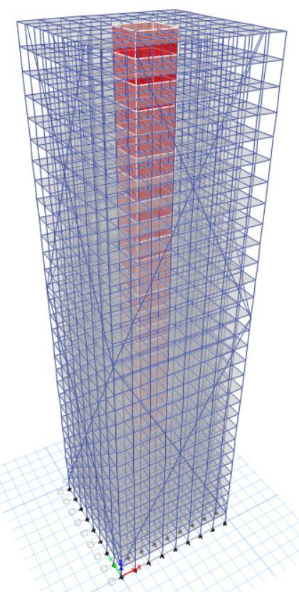
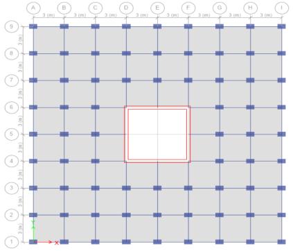
Fig -1:Planand3DModelofRigidFrameBuilding
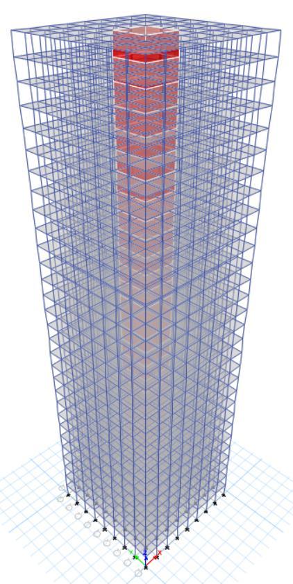

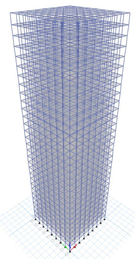
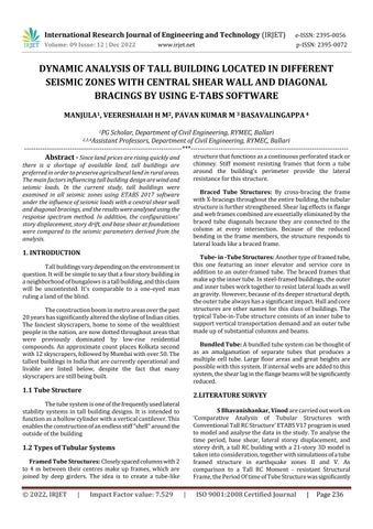
Fig -2:Planand3DModelofTubeinTubeFrameBuilding
International Research Journal of Engineering and Technology (IRJET) e-ISSN:2395-0056
Volume: 09 Issue: 12 | Dec 2022 www.irjet.net p-ISSN:2395-0072
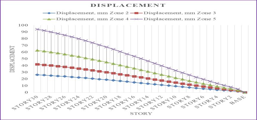
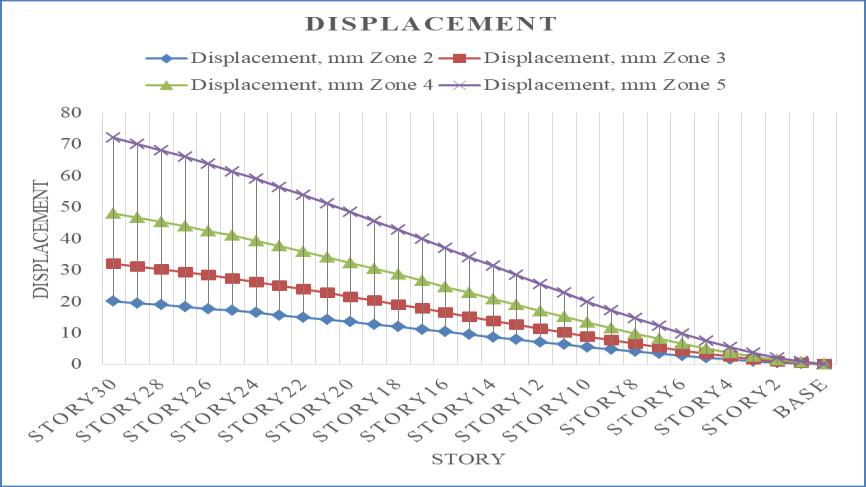
Thedisplacementincreasesalongwiththeseismic zoneintensity,asseenintheabovefigure,andthehighest displacementwasrecordedinseismiczone5.Incomparison to seismic zone 2, displacement has increased by 37.5%, 58.33%, and 72.22% in seismic zones 3, 4, and 5. The top story'sdisplacementistakenintoaccount.
Chart -2:DisplacementforEQY
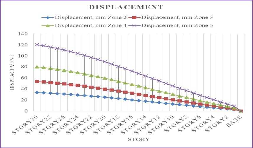
Thedisplacementincreasesalongwiththeseismic zoneintensity,asseenintheabovefigure,andthehighest displacementwasrecordedinseismiczone5.Incomparison to seismic zone 2, displacement has increased by 37.5%, 58.33%, and 72.22% in seismic zones 3, 4, and 5. The top story'sdisplacementistakenintoaccount.
Chart 1 and 2 above show that there is a 21.9% increaseindisplacementsforallzoneswhencomparedto theEQXandEQYloads.Thetopstory'sdisplacementistaken intoaccount.
5. RESULTS AND DISCUSSIONS
5.1.1 Rigid Frame Building
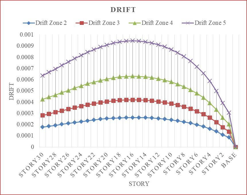
Chart -3:DriftforEQX
Chart -1:DisplacementforEQX
International Research Journal of Engineering and Technology (IRJET) e-ISSN:2395-0056
Volume: 09 Issue: 12 | Dec 2022 www.irjet.net p-ISSN:2395-0072
Ascanbeobservedfromtheprecedingimage,drift increasesalongwithseismiczonestrength,reachingitspeak in seismic zone 5. In comparison to seismic zone 2, the seismic zones 3, 4, and 5 had drift increases of 59.86%, 33.36%, and 33.33%, respectively. The drift is taken into accountfortale1.Whencomparedtotheotherstoriesofthe rigidframetallbuilding,story1isexperiencingthegreatest taledrift.
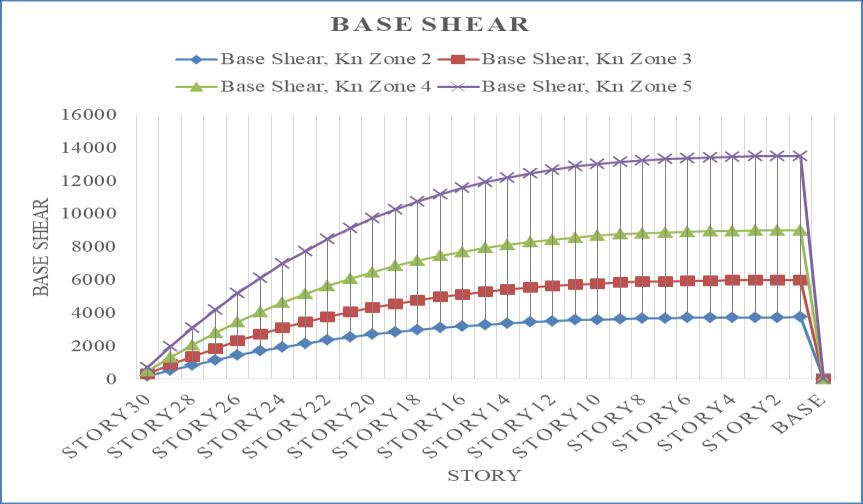
Ascanbeobservedfromtheabovechart,baseshear increasesalongwiththeseismiczoneintensity,withseismic zone5experiencingthehighestbaseshear.Incomparisonto seismic zone 2, seismic zones 3, 4, and 5 see increases in baseshearof37.59%,58.39%,and72.26%.Fornarrative1, thebaseshearistakenintoaccount.
Chart -4:DriftforEQY
Ascanbeobservedfromtheprecedingimage,drift increasesalongwithseismiczonestrength,reachingitspeak in seismic zone 5. In comparison to seismic zone 2, the seismiczones3,4,and5haddriftincreasesof37.53percent, 58.33percent,and72.22percent,respectively.Thedriftis takenintoaccountfortale1.Whencomparedtotheother storiesoftherigidframetallbuilding,story1isexperiencing thegreatesttaledrift.
Chart 3 and 4 above show that there is a 43.84% increaseindriftforallzoneswhencomparedtotheEQXand EQYloads.Fortale1,thedisplacementistakenintoaccount.
Chart
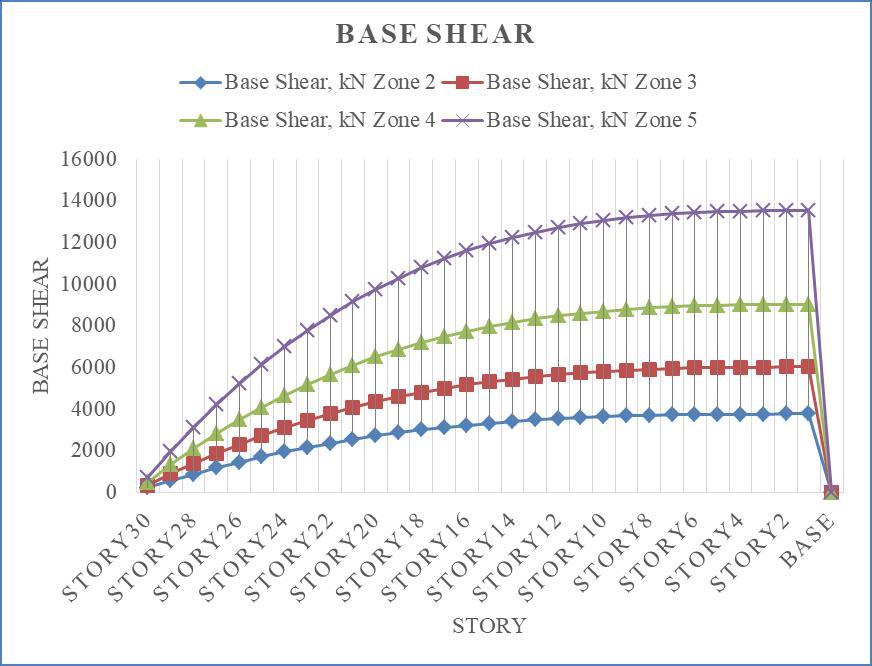
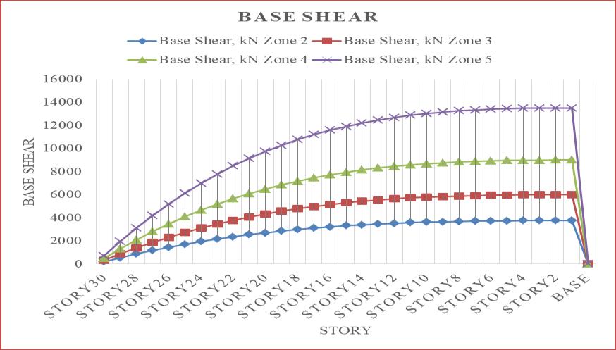
-6:BaseShearforEQY
As can be observed from the above chart, base shear increasesalongwiththeseismiczoneintensity,withseismic zone5experiencingthehighestbaseshear.Incomparisonto seismic zone 2, seismic zones 3, 4, and 5 see increases in baseshearof37.5%,58.33%,and72.22%.Fornarrative1, thebaseshearistakenintoaccount.
Accordingtothechart5and6above,thebaseshear hasincreasedby1.2%forallzoneswhencomparedtothe EQXandEQYloads.Fortale1,thedisplacementistakeninto account.
5.1.2 Tube in Tube Frame Building
Chart -5:BaseShearforEQX
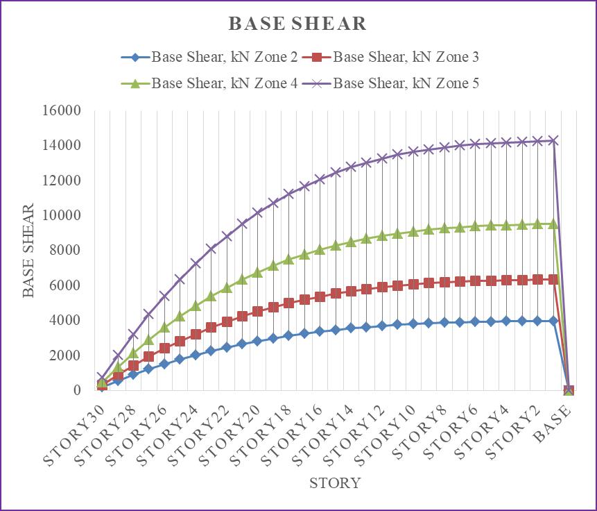
Chart -7:DisplacementforEQX
International Research Journal of Engineering and Technology (IRJET) e-ISSN:2395-0056
Volume: 09 Issue: 12 | Dec 2022 www.irjet.net p-ISSN:2395-0072
Thedisplacementincreasesalongwiththeseismic zoneintensity,asseenintheabovefigure,andthehighest displacementwasrecordedinseismiczone5.Incomparison to seismic zone 2, displacement has increased by 37.5%, 58.33%, and 72.22% in seismic zones 3, 4, and 5. The top story'sdisplacementistakenintoaccount.
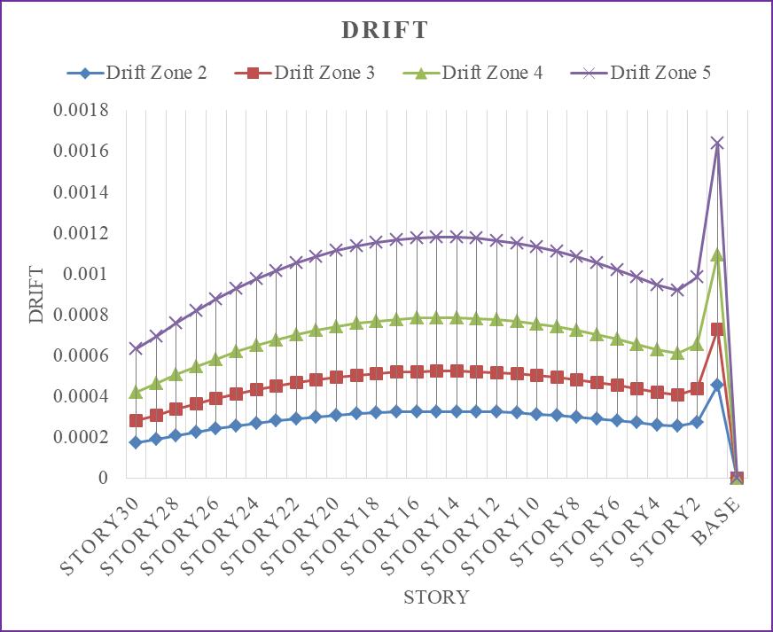
Ascanbeobservedfromtheprecedingimage,drift increasesalongwithseismiczonestrength,reachingitspeak in seismic zone 5. In comparison to seismic zone 2, the seismic zones 3, 4, and 5 had drift increases of 37.99%, 58.69%, and 72.46%, respectively. The drift is taken into account for narrative 15. When compared to the other stories of the tall tube-in-tube construction, story 15 experiencesthegreatesttaledrift
Chart -8:DisplacementforEQY
Thedisplacementincreasesalongwiththeseismic zoneintensity,asseenintheabovefigure,andthehighest displacementwasrecordedinseismiczone5.Incomparison to seismic zone 2, displacement has increased by 37.5%, 58.33%, and 72.22% in seismic zones 3, 4, and 5. The top story'sdisplacementistakenintoaccount.
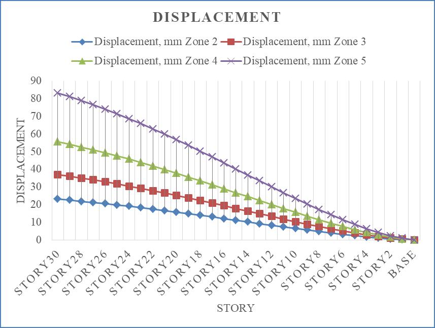
Chart 7 and 8 above show that there is a 13.32% increaseindisplacementsforallzoneswhencomparedto theEQXandEQYloads.Thetopstory'sdisplacementistaken intoaccount.
Chart -10:DriftforEQY
Ascanbeobservedfromtheprecedingimage,drift increasesalongwithseismiczonestrength,reachingitspeak in seismic zone 5. In comparison to seismic zone 2, the seismiczones3,4,and5haddriftincreasesof37.52percent, 58.32percent,and72.22percent,respectively.Thedriftis takenintoaccountfornarrative15.Whencomparedtothe otherstoriesoftherigidframetallskyscraper,story15will experiencethegreatesttaledrift.
Chart9and10aboveshowthatthereisa14.37% increaseindriftforallzoneswhencomparedtotheEQXand EQYloads.Fortale1,thedisplacementistakenintoaccount.
Chart -9:DriftforEQX
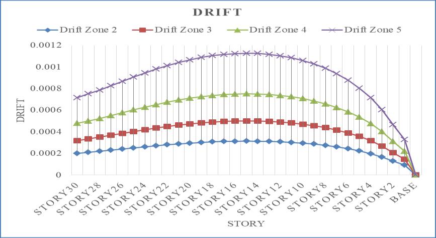
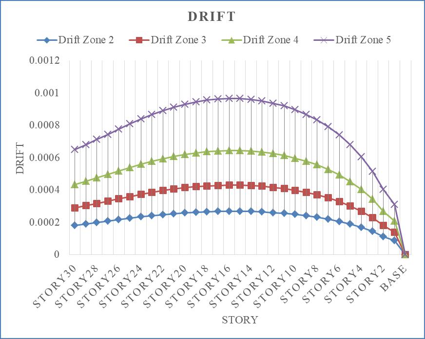
Chart -11:BaseShearforEQX
International Research Journal of Engineering and Technology (IRJET) e-ISSN:2395-0056
Volume: 09 Issue: 12 | Dec 2022 www.irjet.net p-ISSN:2395-0072
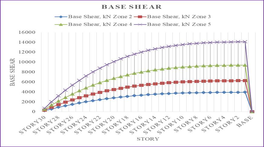
Ascanbeobservedfromtheabovechart,baseshear increasesalongwiththeseismiczoneintensity,withseismic zone5experiencingthehighestbaseshear.Incomparisonto seismic zone 2, seismic zones 3, 4, and 5 see increases in baseshearof37.49%,58.33%,and72.22%.Fornarrative1, thebaseshearistakenintoaccount.
Thedisplacementincreasesalongwiththeseismic zoneintensity,asseenintheabovefigure,andthehighest displacementwasrecordedinseismiczone5.Seismiczones 3,4,and5showdisplacementincreasesof37.49%,58.33%, and 72.22% in relation to seismic zone 2. The top story's displacementistakenintoaccount.
Chart -12:BaseShearforEQY
Ascanbeobservedfromtheabovechart,baseshear increasesalongwiththeseismiczoneintensity,withseismic zone5experiencingthehighestbaseshear.Incomparisonto seismic zone 2, seismic zones 3, 4, and 5 see increases in baseshearof37.5%,58.33%,and72.22%.Fornarrative1, thebaseshearistakenintoaccount.
Chart11and12aboveshowthatthebaseshearhas increasedby0.31%forallzoneswhencomparedtotheEQX and EQY loads. For tale 1, the displacement is taken into account.
5.1.3 Trussed Tube Frame Building
Chart -14:DisplacementforEQY
The displacement increases along with the seismic zone intensity, as seen in the above figure, and the highest displacementwasrecordedinseismiczone5.Incomparison to seismic zone 2, displacement has increased by 37.5%, 58.33%, and 72.22% in seismic zones 3, 4, and 5. The top story'sdisplacementistakenintoaccount.
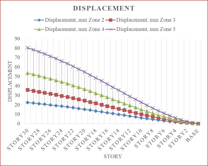
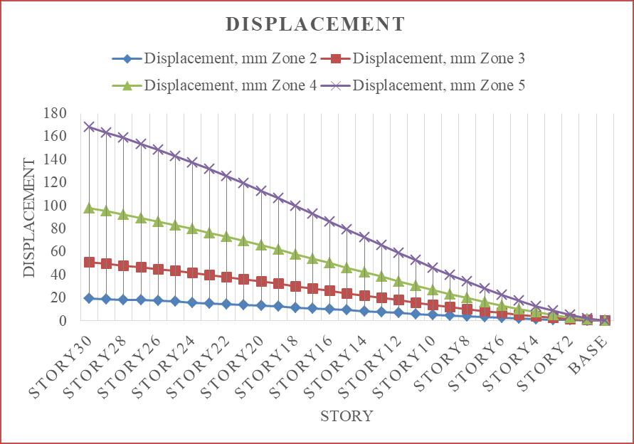
Chart13and14aboveshowthatthereisa12.6% increaseindisplacementsforallzoneswhencomparedto theEQXandEQYloads.Thetopstory'sdisplacementistaken intoaccount.
Chart -13:DisplacementforEQX
Chart -15:DriftforEQX
International Research Journal of Engineering and Technology (IRJET) e-ISSN:2395-0056
Volume: 09 Issue: 12 | Dec 2022 www.irjet.net p-ISSN:2395-0072
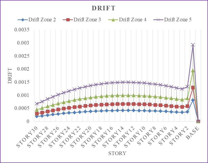
Ascanbeobservedfromtheprecedingimage,drift increasesalongwithseismiczonestrength,reachingitspeak in seismic zone 5. In comparison to seismic zone 2, the seismic zones 3, 4, and 5 had drift increases of 37.52%, 58.38%, and 72.25%, respectively. The drift is taken into account for narrative 15. When compared to the other stories of the rigid frame tall skyscraper, story 15 will experiencethegreatesttaledrift.
Ascanbeobservedfromtheabovechart,baseshear increasesalongwiththeseismiczoneintensity,withseismic zone5experiencingthehighestbaseshear.Incomparisonto seismic zone 2, seismic zones 3, 4, and 5 see increases in baseshearof37.5%,58.33%,and72.22%.Fornarrative1, thebaseshearistakenintoaccount.
Chart -16:DriftforEQY
Ascanbeobservedfromtheprecedingimage,drift increasesalongwithseismiczonestrength,reachingitspeak in seismic zone 5. In comparison to seismic zone 2, the seismic zones 3, 4, and 5 had drift increases of 37.57%, 58.35%, and 72.23%, respectively. The drift is taken into account for narrative 15. When compared to the other stories of the rigid frame tall skyscraper, story 15 will experiencethegreatesttaledrift.
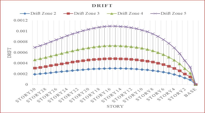
Chart15and16aboveshowthatthereisa13.55% increaseindriftforallzoneswhencomparedtotheEQXand EQYloads.Fornarrative15,thedisplacementistakeninto account.
Chart -18:BaseShearforEQY
Ascanbeobservedfromtheabovechart,baseshear increasesalongwiththeseismiczoneintensity,withseismic zone5experiencingthehighestbaseshear.Incomparisonto seismic zone 2, seismic zones 3, 4, and 5 see increases in baseshearof37.5%,58.33%,and72.22%.Fornarrative1, thebaseshearistakenintoaccount.
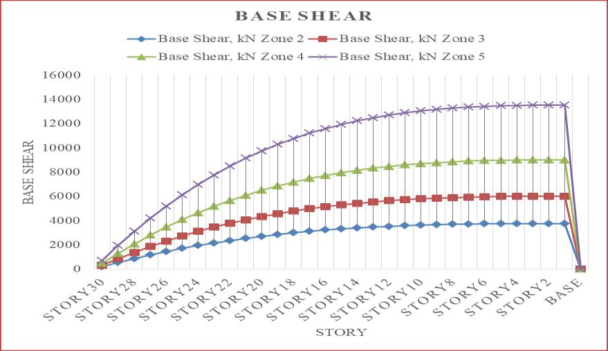
Chart17and18aboveshowthatthebaseshearhas increasedby0.28%forallzoneswhencomparedtotheEQX and EQY loads. For tale 1, the displacement is taken into account.
5.2 Comparison of Different Seismic Zones forRigid Frame, Tube in Tube Frame and Trussed Tube Frame Building for EQY Load
The EQY load values have been used in this comparisonbecause,asshowninclauses5.1.1to5.1.3,the EQYloadproducesthehighestlevelsofdisplacement,drift, andbaseshearwhencomparedtotheEQXload.Asaresult, thecomparisonbelowisconductedforEQYload.
Chart -17:BaseShearforEQX
International Research Journal of Engineering and Technology (IRJET) e-ISSN:2395-0056
Volume: 09 Issue: 12 | Dec 2022 www.irjet.net p-ISSN:2395-0072
Chart -19:Displacement
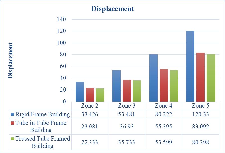
According to chart 19, the trussed frame building experiencesthegreatestreductionindisplacementacross thewholeseismiczonewhencomparedtorigidandtube-intube frame buildings. For all seismic zones, the reduction from a rigid frame building to a trussed frame building is consistentat33.18%.Thereisaconstantdecreaseof3.2% fortubeintubeframedstructuresandtrussedtubeframed buildings, and a constant percentage decrease of 30.94% fromrigidframebuildingstotubeintubeframedbuildings.
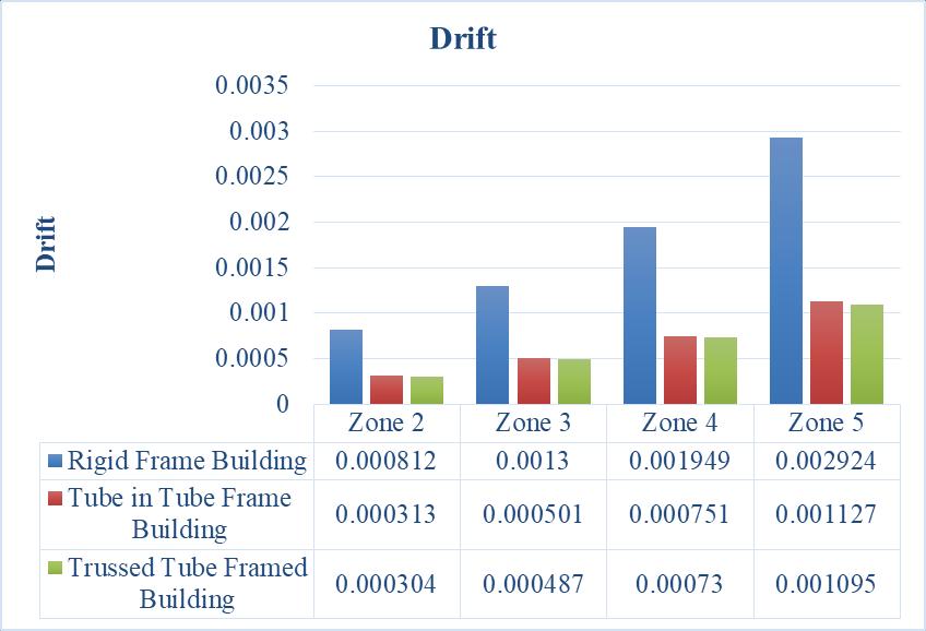
Chart -20:Drift
According to chart 20, the trussed frame building experiencesthegreatestreductionindriftacrossthewhole seismiczonewhencomparedtorigidandtube-in-tubeframe buildings. For all seismic zones, there is a continuous reduction of 62.56% from rigid frame to trussed frame construction.Thereisacontinuouspercentagedecreaseof 62.56% from the rigid frame building to the tube in tube framedbuilding,andthereisaconstantdecreaseof2.87% fortubeintubeframedbuildingsandtrussedtubeframed structures.
Chart -21:BaseShear
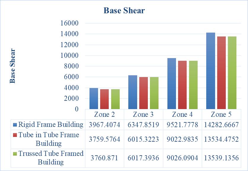
According to chart 21, the trussed frame building experiencesthegreatestreductionindriftacrossthewhole seismiczonewhencomparedtorigidandtube-in-tubeframe buildings.Whencomparingrigidframebuildingstotrussed framebuildings,thereisa continuousdropof5.2%forall seismiczones.Thereisaconstantpercentagegainof0.034% fortubeintubeframedbuildingsandtrussedtubeframed buildings,andaconstantpercentagedropof5.53%forrigid framebuildingstotubeintubeframedbuildings.
6. CONCLUSION
Findingthestabilisationsystemthatismostsuccessfulisa difficult undertaking because it seems there is no single solutionthatcansatisfyallpotentialcriteria.Whilecertain systemshaveadvantagesoverothers,theyarebest suited forsomecriteria.Thefindingsbelowcanbedrawnbasedon theanalysiscoveredinchapter5.
1. Asseismic intensityorzonesgrow, displacement, drift, and base shear for rigid frame, tube in tube framed,andtrussedframedbuildingsallrise.
2. Forallrigidframe,tubeintubeframed,andtrussed framedbuildings,thereisacontinuousincreasein the displacement for both earthquake load in xdirection and y-direction. When compared to the other zones, zone 2 has the least displacement. Whencomparedtozone2,thereisaconsistentrise in displacement of 37.5% (zone 3), 58.33% (zone 4),and72.22%(zone5).
3. Comparedtozone2,rigidframebuildings'driftfor earthquake loads in the x-direction increased by 59.86% (zone 3), 33.36% (zone 4), and 33.33% (zone5).Andwhencomparedtozone2,therigid framebuilding'searthquakeloadinthey-direction increasedby37.53%(zone3),58.33%(zone4),and 72.22%(zone5).
International Research Journal of Engineering and Technology (IRJET) e-ISSN:2395-0056
Volume: 09 Issue: 12 | Dec 2022 www.irjet.net p-ISSN:2395-0072
The drift for tube in tube framed and trussedframedbuildingsiscontinuouslyincreasing forbothseismicloadinx-directionandy-direction. Whencomparedtotheotherzones,zone2hasthe leastdisplacement.Whencomparedtozone2,there isaconsistentriseindisplacementof37.5%(zone 3),58.33%(zone4),and72.22%(zone5).
4. Forallrigidframe,tubeintubeframed,andtrussed framedbuildings,thereisacontinuousincreasein thedriftforbothseismicloadinx-directionandydirection.Whencomparedtotheotherzones,zone 2 has the least displacement. When compared to zone2,thereisaconsistentriseindisplacementof 37.5%(zone3),58.33%(zone4),and72.22%(zone 5).
5. Themaximumvaluesobtainedfortheearthquake load in the y-direction as compared to the xdirectionaredescribedinChapter5
tube framed buildings, and a constant percentagedropof5.53%forrigidframe buildingstotubeintubeframedbuildings.
6. Takingintoaccounttheaforementioneddetails,the trussed tube frame buildings experienced the greatest reduction relative to the others. But as comparedtothetubeintubeframebuildings,there isaminorincreaseinthebaseshearof0.034%.
7. Thefindingsshowthattrussedtubeframebuildings areamongthemosteffectivelateralloadresisting methods employed in tall buildings across all seismiczones.
7.REFERENCES
Throughouttheseismiczone,thetrussed frame building experiences the greatest reductionindisplacementascomparedto rigidandtubeintubeframebuildings.For allseismiczones,thereductionfromarigid framebuildingtoatrussedframebuilding isconsistentat33.18%.Thereisaconstant decreaseof3.2%fortubeintube framed structures and trussed tube framed buildings, and a constant percentage decrease of 30.94% from rigid frame buildingstotubeintubeframedbuildings.
Throughouttheseismiczone,thetrussed frame building exhibits the greatest reductionindriftwhencomparedtorigid and tube in tube frame buildings. For all seismic zones, there is a continuous reduction of 62.56% from rigid frame to trussed frame construction. There is a continuouspercentagedecreaseof62.56% fromtherigidframebuildingtothetubein tube framed building, and there is a constantdecreaseof2.87%fortubeintube framedbuildingsandtrussedtubeframed structures.
Throughouttheseismiczone,thetrussed frame building exhibits the greatest reductionindriftwhencomparedtorigid and tube in tube frame buildings. When comparingrigidframebuildingstotrussed framebuildings,thereisacontinuousdrop of 5.2% for all seismic zones. There is a constant percentage gain of 0.034% for tubeintubeframedbuildingsandtrussed
1. SBhavanishankar,Vinod,“ComparativeAnalysisof Tubular Structures with Conventional Tall RC Structure”, International Research Journal of Engineering and Technology (IRJET) Volume: 08 Issue:03|Mar2021.
2. Mrunal P Kawade , Vivek S Bangde , G H Sawai, “SeismicAnalysisofTallBuildingwithCentralCore as Tube Structure”, International Journal of Progressive Research in Science and Engineering Volume-1,Issue-6,September-2020.
3. SindhuNachiarS,AnandhS,SaiPavithraS,Lakhan Kumar Saini, Elina Thomas, Boojith C S, “ComparativeSeismicAnalysisofConventionaland RCC Tube in Tube Structure with Pentagonal and HexagonalGeometrySubjectedToLateralLoadsin Different Zones”, International Journal of Engineering and Advanced Technology (IJEAT) ISSN:2249-8958,Volume-8Issue-4,April2019.
4. E.H.Ghoniem, Nihal M.Ayyash, Ahmed Essam, “Seismic Response of High-rise Buildings with DifferentStructuralSystems”,InternationalJournal ofEngineeringandInnovativeTechnology(IJEIT) Volume8,Issue9,November2018.
5. Pavithra S E, Dr. S Vijaya, Kavya H K, “Dynamic Analysis of Hybrid Tall Tube Structural system”, NOVYIMIRResearchJournal,ISSNNo:0130-7673, Volume5,Issue12,2020.
6. Mr.DhruvilYPatel,Mr.PiyushJain,Dr.V.R.Patel, “Analysis and Design of RCC Tall-Building with differentstructuralsystems”,InternationalJournal of Innovative and Emerging Research in EngineeringVolume4,Issue5,2017.
7. Wuit Yi Win Htut, “A Simplified Approach for Optimization of Tube System in Tall Buildings”, International Journal for Innovative Research in
International Research Journal of Engineering and Technology (IRJET) e-ISSN:2395-0056
Volume: 09 Issue: 12 | Dec 2022 www.irjet.net p-ISSN:2395-0072
MultidisciplinaryFieldISSN–2455-0620Volume2,Issue-9,Sept–2016.
8. Akshay S. Patil, Roshni John, “Performance Evaluation of Unsymmetrical HighRise Building with Different Types of Structural Techniques for Critical Load Condition”, International Journal of Scientific&EngineeringResearchVolume11,Issue 4,April-2020.
9. Neelam.Sathyanarayana, G.Srinath, E.Giriprasad Goud, “Seismic Comparison Between the Use of Framed Shear Wall System and Framed Tube SysteminTallBuildings”IndianJ.Sci.Res.17(2):429 -433,2018.
10. Deepak Suthar, H.S.Chore, P.A. Dode, “High Rise Structure Subjected To Seismic Forces And Its Behavior”, Proceedings of 12 th IRF International Conference,29thJune-2014.
11. Patil. Kiran Kumar, Chandan Kumar. Patnaikuni, Balaji .K.V.G.D, B. Santhosh Kumar, “Seismic PerformanceofBundledTubeStructuresinSeismic ZoneIV&ZoneVofIndia”,InternationalJournalof AdvancedResearchinEngineeringandTechnology (IJARET)Volume11,Issue6,June2020.
12. Jignesha Patel, Roshni J John, “Seismic Analysis of Frame Tube Structure”, International Journal of Scientific&EngineeringResearch,Volume6,Issue 12,December-2015.
13. NimmyDileep,RenjithR,“AnalyticalInvestigation on the Performance of Tube-In-Tube Structures SubjectedtoLateralLoads”,InternationalJournalof Technical Research and Applications, Volume 3, Issue4July-August2015.
14. Moreteza Deiranlou, “Evaluation of Seismic BehaviorinBuildingTubeStructuresSystemwith RespecttoDenseSoil-StructureInteractionEffect”, OpenJournalofCivilEngineering,2015.
15. Shruthi L, S. Vijaya, “Seismic Analysis of Latticed Shell Tube RC Framed Building”, International Journal of Engineering Research & Technology (IJERT)IJERTISSN:2278-0181www.ijert.orgVol.3 Issue7,July–2014.
16. Gurudath C, Ganesh Bahadur Khadka, Hafiz Faiz Karim,“AnalysisofMulti-StoreyBuildingwithand withoutDiagridSystemUsingETABS”,International Journal Of Innovative Research In Technology, Volume5Issue12,ISSN:2349-6002,May2019
2022, IRJET | Impact Factor value: 7.529 | ISO 9001:2008 Certified Journal |