International Research Journal of Engineering and Technology (IRJET) e-ISSN: 2395-0056

Volume: 09 Issue: 12 | Dec 2022 www.irjet.net p-ISSN: 2395-0072
Performance Based Evaluation of Existing RC Building in Chiplun, Maharashtra.
Mr. Sujit Joshi1 and Dr. Chetan S. Patil21PG Student, Department of Civil Engineering, Sanjay Ghodawat Group of Institutions, Kolhapur, Maharashtra, India.
2Assistant Professor, Department of Civil Engineering, Sanjay Ghodawat Group of Institutions, Kolhapur, Maharashtra, India. ***
Abstract - Civil engineers deal with earthquakes in seismically active areas. Earthquakes causebuildingcollapses and deaths in cities. Older buildings designed with outdated laws and architectural norms may not meet seismic design standards. Outdated rules and codes. This study analysed an older structure's seismic load to evaluate retrofitting needs. The building met Eurocode8'sseismic normsafterretrofitting. 1970 concrete structure in Chiplun, Maharashtra, India. India's Maharashtra. ETAB software evaluates seismicity. Building seismic reactivity is determined by two analyses. Before and after retrofitting, modal analysis is undertaken. This analysis measures torsional strength. Pushover analysis compares construction deformation to target displacement. The building's target displacement. This displacement must not be exceeded for structural integrity. If the projected displacement is greater, the structure's weaknesses must be recognised and retrofitted. If goal displacement is lower, the comparison is useless. Analyzing pushover before and after retrofitting.
Eigenvalue and pushover analyses indicated the building's torsional sensitivity and shear failures. Both were found after inspection. The structure is weak. The desired displacement did not exceed the structure's displacement when the building's initial member reached a limit condition. True. The building didn't collapse. Many beams sheared when X-shaped steel bracing were installed. This increased stiffness and torsional resistance.Somesteel-bracedcolumnscollapsed. Wrapping the structure's problematic members in fiberreinforced plastic prevented shear and compression failures. Possible shear failures. Reduced seismic risk.Afterretrofitting, the building met India's current seismic design regulations. This project thesis could lead to greater earthquake damage prevention and seismic retrofitting research.
Key Words: Pushover analyses, Retrofitting, Torsional strength,Structuralintegrity,Stiffnessetc.
1. INTRODUCTION
Earthquakes are the most destructive natural hazard.Insteadthantryingtopreventdamageandminimise economic losses, seismic design should emphasise life protection. Because reducing damage could threaten a building's structural stability. In contrast to force-based
techniques, displacement-based seismic design gives a logical procedure for estimating a building's earthquake resistance.Nonlinearstaticapproachesarepopular.Based on the design response spectrum, these methods provide direct information on the size and distribution of plastic strainsinastructure.Thisisdonewithoutthechallengesof non-linear time-history analysis and the need to identify appropriategroundmotiontimehistories.Staticpushover study reveals the structure's strength, ductility, and progressive manner of collapse. Therefore, the strategy emphasisesperformanceoverstrength.
Already-built structures are compared to newlybuilt structures' performance requirements. This part establishes the minimum evaluation criteria for expected life-safetyperformanceofexistingbuildingswithnecessary adjustmentstoIS:1893seismicforce,whichappliestothe seismic design of new buildings. Existing buildings must meet these seismic standards. Because this code has a significantassociationwithIS:1893'sdesignstandardsfor new buildings, it must always be referred to. All existent structural elementsmustbe abletocarryfull non-seismic loads under current loading and material strength regulations.
"Nonlinear Static Analysis to Assess Seismic PerformanceofCode-ConformingRCBuildings"(2012).This studyanalyses4-and6-storyRCconstructionsinIndia.IS: 456-2000 and IS: 1893-2002 are applicable standards. Designing ordinary and outstanding moment-resisting frames(SMRF).Pushoverstudycapturesimmediateyielding, steady progressive plastic behaviour, and total building reactiontoseismicexcitations.Pushoveranalysissimulatesa plastic hinge by deforming structural parts. Analytical methods analyse beams' yield, plastic, and final rotation capabilities and plastic hinge lengths. This study model’s user-definedplastichingepropertiesofbeamsandcolumns utilising Eurocode 8 analytical expressions and SAP2000 pushoveranalysis.TheseidiomsreferenceEurocode8.Basic load patterns are analysed nonlinearly. Based on member materials and dimensions, the analysis evaluates the structuralsystem'sseismiccapacity.
Pavan Kumar et al. (2012) studied seismic retrofittinginzonev.Theyfoundmaterialsandprocesses.
International Research Journal of Engineering and Technology (IRJET) e-ISSN: 2395-0056
Volume: 09 Issue: 12 | Dec 2022 www.irjet.net p-ISSN: 2395-0072
TheysummarisedusingSAP2000.Accordingtostudy,fivestory buildings could expect increased seismic damage. A building's seismic resistance determines whether to strengthenit.Abuilding'searthquakeresistancedetermines whethertofortifyit.Buildingslacksufficientseismicdesign anddetails,thusretrofittingoptionsareexamined.India's seismic zones need upgrading. This study offers many retrofitting methods, such as plate binding and steel jacketing, and building element materials, such as ferrocement,glassfibre,HPFRCC,FRPstrips.
In Rama Raju et al. (2012), a typical reinforced concrete (RC) structure frame is designed for four design cases according to three modifications of IS: 1893 and IS: 456, and user-defined nonlinear hinge characteristics or default-hinge (DF) properties are analysed in SAP 2000 basedonFEMA-356andATC-40requirements.IS-1893and IS-456 were revised three times. 6-story concrete frame. Inelastic hinge effect for columns as P-M-M curves and beamsasM3curves.AnalyticalapproachforanalysingRC construction yield, plastic, and rotation capacity. A threeparametermodelisemployedforRCelementsbeyondthe post-yield area of restricted concrete. Nonlinear static analysis evaluates building component performance. The effect of default and user-defined nonlinear component propertiesonpushoveranalysisresultsisstudied.
Poluraju and Nageswara presented pushover analysisusingSAP2000.(2012).Non-linearstaticpushover analysis was used to assess framed buildings' seismic resilience.G+3wasinspectedforthis.
Kadid and Bourmrkik studied concrete frame pushover(2008).Theseismicresistanceofframedbuildings was evaluated using nonlinear static pushover. This aim required 5-, 8-, and 12-story framed buildings. Older concretestructuresneedseismicrestorationinearthquakeprone areas. Identifying vulnerable infrastructure and defining safety is crucial. Recent performance-based guidelines for designing or modifying structures in earthquake-proneareasshowthat"pushoveranalysis"can predictabuilding'sdamagerisk.Performance-basedcodes show this. These construction codes are utilised for earthquake-pronebuildings.
Kumbhar researched earthquake-proofing techniques (2007). G+3 employs SAP 2000 for seismic evaluation. Alternative load combinations are evaluated usingthree-dimensional modelsandlinearstaticanalysis. Existing buildings in earthquake-prone zones undergo screening (Tier 1), evaluation (Tier 2), and detailed evaluation (Tier 3). (Tier 3). This study uses a four-story hospitaltodemonstrateandexplainseismicevaluation.
Durgesh(2005)offersa methodforassessinga building's life safety. This strengthens a building. Unfavorable architecturalelementsthatcouldruinacomponentorthe wholestructureareidentified.
AccordingtoSucuogluetal.,recentearthquakesin Turkeydamaged130reinforcedconcretebuildings(2004). Shearwallswerecreatedtorestorethesebuildingstotheir previousglory.Inthestudy,multipleseismicperformance evaluation approaches are used to forecast damaged structures'performances.Then,renovationperformanceis analysed. Nonlinear static and dynamic techniques are equally accurate at predicting building performance. Nonlinear member performance ratios indicate linear spectraldemand-to-capacityratios.
WenjunGuoetal.(2003)discoveredstructuresfall slowly.Weprovideasimpledesigncriterionforstructural members.Toshowprogressivecollapseanalysis,wecreatea single-degree-of-freedom model. Existing buildings are analysed nonlinearly. This approach compares a 6-story concretestructuretoanonlineardynamiccomputation.The authors illustrate progressive collapse using a nonlinear springandaconcentratedmass.SectionIexplains.Second portion offers existing building nonlinear static analysis. Based on energy balancing, the structure must be able to absorb the potential energy produced by eliminating one column.
2. ANALYSIS OF EXITING STRUCTURE
This project involved studying and retrofitting an old building in Chiplun. The corporation chose this 1970 Indian-Regulation building for its operations. Given these factors, the structure is vulnerable to seismic events and mustberetrofittedtobesafeandconformwiththeIndian Code.24metreslong,18metreswide.Thebuilding'stallest pointis16m.Ithasfour6-mbaysonthelongsideandthree on the short side. Each store is 3.2 m tall. Not counting ground level. The building's floor plan and elevation are rectangular.Theconstructionhasacentralelevatorshaft.
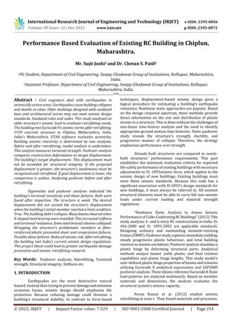
Figure 1. Thedrawingintheplanofthebuilding.
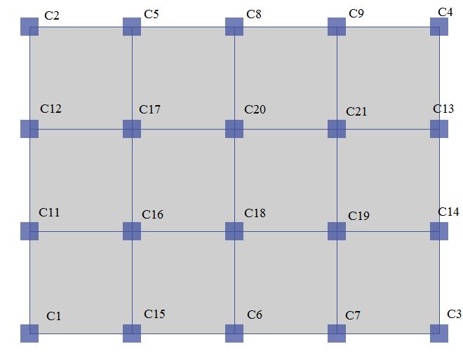
Figure2showstheETABsoftware'sfinal3Dmodel.Thelong side has four bays with a 6.0 m spread along the X axis (showninred),andtheshortsidehasthreebayswitha6.0m spanalongtheYaxis.Redrepresentsbothsides(shownwith greencolor).Longsideis24.0m,shortsideis18.0m.The
International Research Journal of Engineering and Technology (IRJET) e-ISSN: 2395-0056
Volume: 09 Issue: 12 | Dec 2022 www.irjet.net p-ISSN: 2395-0072
diagramshowsthatthebuildinghasfour3.2-m-highstories (this height does not include the ground level). The walls' weight is regarded a homogenous load on the beams, althoughtheyarenotdepicted.Modelusesfixedsupports. Thisisanassumptionmadetodeterminehowthegroundfloor columns are connected. Any fixed support is 0.00 m belowground.
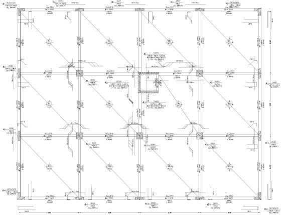
Figure3showsaconcretebuildingsection.Theelevatorshaft isnearlyequidistantfromthebuilding'sends.Theelevator shaftwallsarecolumnsbecausethreebeamsarelinkedto them.Usingsoftwareconstraints,thelinkwasmade.Tables1 &2describethebeamsandcolumns,includingtheirsizeand steelreinforcing.
Table 1. Information’softhecolumns
Name Dimension s (mm) Longitudinal reinf. Transverse Reinf.
C1,C2,C3,C4 3000x675 12#16+2#20 8mm # @ 300mmC/C.
C5, C6, C7, C8, C9, C10,C11,C14,C15 450x900 8#20+2#16 8mm # @ 150mmC/C.
C12,C13 375x900 8#20+2#16 8mm # @ 120mmC/C.
C16, C17, C18, C19, C20 600x600 12#20 8mm # @ 110mmC/C.
Table 2. Information’softhebeams
Name Dimensions (mm) Longitudinal Reinf. Transverse Reinf.
B1, B2, B3, 4, B5, B7, B8, B9, B10, B11,B12,B13,B14, B23,B24,B25 250x450
B15,B16,B17,B18, B19,B20,B21,B22 250x600
B26,B27,B28,B29, B30,B31 300x600
Top:2#10, Bottom:5#12 #8mm @ 300mmC/C.
3. ANALYSIS OF THE EXISTING BUILDING
3.1 Modal Analysis
The non-retrofitted building underwent a modal study. This section analyses torsional sensitivity by estimatingtheeffectivemodalmasspercentages.Whenthe firsttwomodeshavealmost85%effectivemodalmassand aretranslationalalongtheXandYaxes.Thehighesteffective modal mass percentage for each mode is evaluated. The results show the actual modal mass percentages. The first modeisrotatingalongtheZaxisandhas73.45%effective modal mass (the highest percentage for the first mode). SecondandthirdmodesaretranslationalintheYandXaxes, andtheireffectivemodalmasspercentagesare67.30%and 61.80%. The first mode spins along the Z axis and has a modal mass percentage of 73.45%. Due to its design and stiffnessdistribution,thepre-retrofittedbuilding'seffective modalmasspercentagescouldn'tbehigher.Duetothesmall gapbetweentheresultsandallowablepercentages,itwasnot possibletosaywithcertaintythattorsionalsensitivityhad beeneradicated.Thebuilding'storsionbehaviourhadbeen considerably decreased, thus it was unlikely to cause difficulties.
Top:2#10, Bottom:4#16 #8mm @ 225mmC/C.
Top:2#10, Bottom:5#16 #8mm@175 mmC/C.
The computation of the building's dead loads considersthecomponents'individualweightsaswellasthe buildingitself.Ithasbeentakenintoconsiderationthatthe self-weightofthewallswillplaceanadditionalpressureon thebeams.Theadditionalpermanentloadof8.0kN/mthatis imposed by the structure's outside walls, which are positioned along the perimeter of the structure, must be handledbytheperimeterbeamsofthestructure.Beamsare capable of carrying an additional permanent load of 4.50 kN/mthatisappliedtotheinternalwalls.Theslabshavelive loadsof2.00kN/m2
Figure2.Thethree-dimensionalmodeloftheexisting building.
Figure3.Theplanoftheexistingbuildingwiththenamed columnmembers.
2022, IRJET | Impact Factor value: 7.529 | ISO 9001:2008 Certified Journal
International Research Journal of Engineering and Technology (IRJET) e-ISSN: 2395-0056
Volume: 09 Issue: 12 | Dec 2022 www.irjet.net p-ISSN: 2395-0072
3.2 Nonlinear Static Pushover Analysis
Noneofthebuilding'smembersexceededthelimit states,ensuringevenloaddistribution.Severalmembersbent atlargerdisplacementsthanexpected(targetdisplacements). Nobendingfailuresoccur.MaximumbaseshearforcealongX and Y axes is 3850 kN for applied loads. First members exceeded shear capacity for X-axis stress uniformity. The buildingmoved0.006mandsheared570.00kN.Whenthe load was distributed equally along the Y axis, the first structuremembersexceededtheirshearcapacityat0.003m displacement and 285.00 kN base shear. Beams failed in shearforXandYloadings.Thebuildingneededmodifications before it could be judged safe. Figures 5 and 6 show the capacitycurvesforXandYloadings.Thesegraphicsshowthe intendeddisplacementsandthedisplacementswhenthefirst memberreachedeachlimitstatealongthecapacitycurves.
Figure4.Theplanoftheexistingbuildingwiththenamed beammembers.
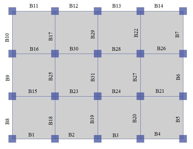
Table 3. Displacementalongthe‘X’axiswhentheinitial memberofanexistingstructurereachedeachlimitstate.
Limit state Target Displacement (m)
Displacement First member reached the limit state (m)
Status
LifeSafety(LS) 0.034 0.071 Accepted Immediate Occupancy(IO) 0.044 0.108 Accepted Collapse Prevention (CP) 0.077 0.142 Accepted
N) ar (k She Base
N) ar (k Base
FirstElement_CP
FirstElement_IO
BaseShear LifeSafety(LS) ImmediateOccupancy(IO) CollapsePrevention(CP)
5000 4000 3000 2000 1000 0.00.10.20.3 0
Displacement(m)
Figure 5. Capacitycurvewithtargetdisplacementsalong the‘Χ’‘axisforExitingStructure.
Table 4. Displacementalongthe‘Y’axiswhentheinitial memberofanexistingstructurereachedeachlimitstate.
Limit state Target Displacement (m)
Displacement First member reached the limit state (m)
Status
Base Shear (kN)
4000
3000
2000
5000 Base Shear (kN)
1000
FirstElement_CP FirstElement_IO
BaseShear LifeSafety(LS) ImmediateOccupancy(IO) CollapsePrevention(CP)
LifeSafety(LS) 0041 0062 Accepted Immediate Occupancy(IO) 0.053 0.121 Accepted Collapse Prevention (CP) 0084 0163 Accepted 0.0 0.1 0.2 0.3 0
Displacement(m)
Figure 6. Capacitycurvewithtargetdisplacementsalong the‘Y’‘axisforExitingStructure.
4. RETROFITTED BUILDING WITH STEEL BRACES
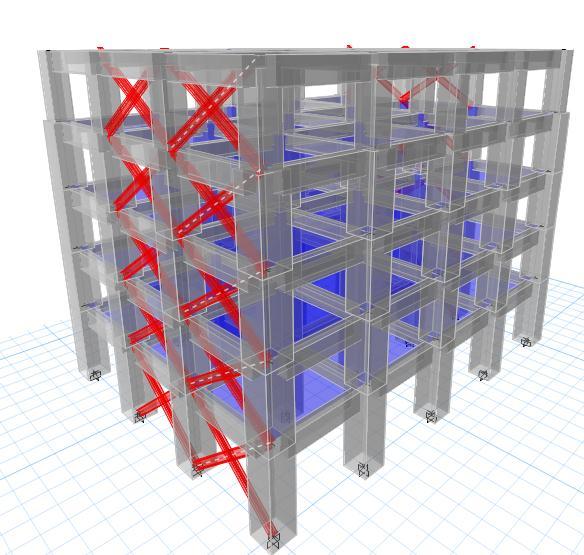
Globalretrofittingischosentoimprovetheexisting building. Due to the original building's poor earthquake response, concentric X-shaped steel supports were added. Steel bracing provide additional structural rigidity and transferseismiclateralloadstotheground.Steelbracingis
International Research Journal of Engineering and Technology (IRJET) e-ISSN: 2395-0056
Volume: 09 Issue: 12 | Dec 2022 www.irjet.net p-ISSN: 2395-0072
used to support excess weight caused by earthquakes and relievepressureonolderareasofthestructure.Steelbraces areoverwhelmedbythemodifiedframe'sabilitytoabsorb seismicenergy.Thisdeservesdiscussion.Themembersfail whentheconcrete'scompressivecapacityisexceeded.Steel bracingalsochangeshowthebuildingtransfersitsloadsto theground.Duetothenewlyproducedload"paths,"certain previouslyinvulnerablemembersmaynowfail.Then,afresh seismicevaluationandretrofittingshouldbedone.
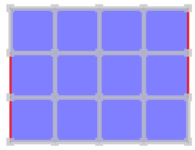
Steel bracing can offer a building greater rigidity. Global retrofitting reduces or eliminates the structure's torsional sensitivity. In this study, steel bracing are constructed around the building's perimeter to evenly distribute the structure's stiffness along the X and Y axes. Thismaintainsstructuralsymmetry.Figure7showsthesteel bracesonredframes.IS2062gradeWFBsectionsareused forthisconstruction'ssteelcomponents.Table5listsfloor cross-sections. As floor levels rise, greater steel member crosssectionsarenolongerneeded.Figure8illustratesthe bracedstructurein3D.
Figure 8 The3Dmodeloftheretrofittedwithsteelbraces building.
5. ANALYSIS OF THE RETROFITTED BUILDING
5.1 Modal Analysis
Figure 7. Thepositionoftheinstalledsteelbraces(with redcolor).
Table 5. Thesteelbracesoneachlevelfloor.
Floor level Steel brace cross section Steel class
Ground-floor WB450 IS2062
1stfloor WB400 IS2062
2ndfloor WB350 IS2062
3rdfloor WB350 IS2062
4rthfloor WB300 IS2062
The retrofitting technique that involved installing steel braces in the structure changed how the building behaved.Thebuilding'srigiditywasraisedasaresultofthe retrofitting technique including steel bracing. It is readily clear that the periods are shorter and the frequencies are higher than they were in the building before to the retrofittingbecauseoftheincreasedstiffness.Theeffective modalmasspercentageschangedasaresultofplacingthe steelbracingstrategicallyinframeslocatedonthebuilding's edge.Asaresult,theeffectivemodalmasspercentagesofthe firsttwomodes,whicharetranslationalintheXandYaxes, are78.60and74.07%,respectively.Thethirdmodehasan effective modal mass percentage of 69.52 % and rotates aroundtheZaxis.
5.2 Nonlinear Static Pushover Analysis
None of the building's modified steel braces exceededload-distributionlimits.Bendingfailuresaren'tan issue. The goal displacements are higher than the current buildings. The building received a maximum X-axis shear forceof4,500kN.Duetothesteelbracing,thebuildingwas subjectedtoamaximumY-axisshearforceof11000kN.The steelbracesworkedeffectivelyandwithstoodY-axisloading, thus this is apparent. Some beams' shear capabilities are reached early, likely due to insufficient transverse reinforcing.Whenthebuildingmoved0.006mandthebase shearreached628.012,theinitialmemberssurpassedtheir shearlimitforuniformloaddistributionalongX.Theseinitial shear-failedcomponentswerealllong-sidebeams,asshown in Figure 9. Initial building members sheared at 0.006 m displacementand2641.50kNbaseshear.WhenYwasloaded equally,thishappened.Figure10showsbeamsonthelongor
International Research Journal of Engineering and Technology (IRJET) e-ISSN: 2395-0056
Volume: 09 Issue: 12 | Dec 2022 www.irjet.net p-ISSN: 2395-0072
short side of the building. When loaded along the Y-axis, capacitydroppedquickly(Figure9).Thishappenedwhena steel-bracedcolumncouldn'thandleaxialstressesandfailed undercompression(Figure10belowshowsthecolumnthat failed). Shear and compression issues made the structure unsafe to occupy. To prevent problems, the structure was renovated a second time with steel braces and a local retrofittingstrategy.
Table 5 Displacementalongthe‘X’axiswhenthe initialmemberofanexistingstructurereachedeachlimit stateforretrofittedbuilding.
Limit state Target Displacement (m)
Displacement
First member reached the limit state (m)
Status
LifeSafety(LS) 0.067 0.078 Accepted
10000
5000
4000
FirstElement_CP
FirstElement_IO
Base Shear (kN)
Base Shear (kN)
3000
2000
1000
BaseShear LifeSafety(LS) ImmediateOccupancy(IO) CollapsePrevention(CP)
Immediate Occupancy(IO) 0.087 0.112 Accepted Collapse Prevention(CP) 0.141 0.186 Accepted 0.0 0.1 0.2 0.3 0
Displacement(m)
Figure 9 Capacitycurvewithtargetdisplacementsalong the‘Χ’‘axisforretrofittedbuilding.
Table 6. Displacementalongthe‘Y’axiswhenthe initialmemberofanexistingstructurereachedeachlimit stateforretrofittedbuilding.
Displacement
Limit state Target Displacement (m)
First member reached the limit state (m)
Status
LifeSafety(LS) 0.021 0.032 Accepted
Immediate Occupancy(IO) 0.034 0.104 Accepted
Collapse Prevention(CP) 0.044 0.128 Accepted
Factor value:
8000
6000
4000
12000 Base Shear (kN)
2000
FirstElement_IO
Base Shear (kN) FirstElement_CP
BaseShear LifeSafety(LS) ImmediateOccupancy(IO) CollapsePrevention(CP)
0.0 0.1 0.2 0.3 0
Displacement(m)
Figure 10. Capacitycurvewithtargetdisplacementsalong the‘Y’‘axisforretrofittedbuilding.
6. CONCLUSIONS
Ananalysisofthefindingsshowsthatafterseismic retrofitting,thebuilding'searthquakebehaviourimproved dramatically. The building's structural integrity must be enhanced to withstand earthquakes, according to seismic assessments.Variousseismicassessmentshelpedattainthis goal. The improvements prevented bending, shear, and compression failures. The existing building had a high torsional sensitivity and the bulk of its beams had a poor shear capacity due to insufficient transverse reinforcing. Insufficient transverse reinforcement prevented confinement in the structure's concrete elements. No buildingmembersfailedinbending,hencethelongitudinal reinforcementwasprobablysufficient.
Steel braces improved the building's torsional sensitivity.Thebuilding'soverallrigidityincreased,andit could withstand greater Y-axis seismic loads. Massive seismicstressespassedthroughsteelbracingcausedcolumn breakdownsinthesameframes.Thesteelbracingdidnot reduce the seismic loads on the beams, therefore shear failures occurred again. This study offers new insights on how to monitor seismic behaviour and fortify existing structures. [Seismic activity and building resistance] To fortifyanexistingstructureandmeetconstructionlawsand standards,youmustunderstandretrofittingtechniquesand theirapplications.
REFERENCES
[1] Bai J., 2003. Seismic Retrofit for Reinforced Concrete Building Structures, Consequence-Based Engineering InstituteFinalReportatTexasA&MUniversity,Texas, USA,Lastaccessed(21-012019).
[2] BouvierC.,2003.TechniquesofSeismicRetrofittingFor Concrete Structures. Massachusetts Institute of Technology,Massachusetts,USA,Lastaccessed(22-022019).
International Research Journal of Engineering and Technology (IRJET) e-ISSN: 2395-0056
Volume: 09 Issue: 12 | Dec 2022 www.irjet.net p-ISSN: 2395-0072
[3] Carrillo,J.,Hernández-Barrios,H.,Rubiano-Fonseca,A., 2013. Analysis of the EarthquakeResistant Design Approach for Buildings in Mexico. Ingeniería Investigación y Tecnología, 15(1), pp. 151-162, Amsterdam,Netherlands,Lastaccessed(25-01-2019). Retrievedfrom:http://www.elsevier.es
[4] CetinS.,2014.Seismicretrofittingofexistingstructures. Civil and Environmental Engineering Master's Project Reports7.PortlandStateUniversity,Portland,USA,Last accessed(13-012019).
[5] DiSarnoL.,ElnashaiA.S.,2002,Seismic retrofittingof steel and composite building structures, Civil and EnvironmentalEngineeringDepartmentatUniversityof IllinoisatUrbanaChampaign,Illinois,USA,Lastaccessed (14-03-2019).
[6] DritsosS.E.,2015.Seismicassessmentandretrofitting ofstructures:Eurocode8-Part3andtheGreekcodeon seismic structural intervantions, University of Patras, Patra, Greece, Last accessed (01-03-2018). Retrieved from:https://www.iabse.org
[7] DuthinhD.,StarnesM.,2001.StrengthandDuctilityof ConcreteBeamsReinforcedwithCarbonFRPandSteel. National Institute of Standards and Technology, Gaithersburg,USA,Lastaccessed(14-12-2018).
[8] GkournelosD.P.,BournasD.A.,Triantafillou,T.C.,2019. Combined seismic and energy upgrading of existing buildingsusingadvancedmaterials.PublicationsOffice oftheEuropeanUnion,Brussels,Luxembourg.
[9] Husain M., Hassan H., Elhamid M.A., Elgharbawy E.S., 2017, Seismic Evaluation and Strengthening of RC FrameswithFRPComposites,InternationalJournalof EngineeringResearch&Technology(IJERT),Vol.6Issue 02, Gandhinagar, India, Last accessed (01-04-2019) Retrieved from: https://www.ijert.org/seismicevaluation-and-strengthening-of-rc-frameswith-frpcomposites
[10] Jaspart,J.,&Weynand,K.,2016,Designofjointsinsteel andcompositestructures:Eurocode3:Designofsteel structures,Part1-8-Designofjoints,Eurocode4:Design of composite steel and concrete structures, Part 1-1General rules and rules for buildings (ECCS Eurocode design manuals), pp. 392-398, Weinheim, Germany: Wiley‐VCHVerlagGmbH&Co.KGaA.
[11] KrawinklerH.,SeneviratnaG.D.P.K.1998.Engineering structures. Pros and cons of a pushover analysis of seismicperformanceevaluation.Vol.20,Issues4–6,pp. 452-464,GreatBritain:ElsevierScienceLtd.
[12] LavocatJean-Christophe,2014,Activephotonicdevices based on liquid crystal elastomers. Fabrication and
applications, Tuscany, Italy, 10.13140/RG.2.1.1053.4644. Last accessed (01122018).
[13] Motavalli,M.,&Czaderski,C.,2007,FRPcompositesfor retrofittingofexistingcivilstructuresinEurope:Stateof-the-art review. Presented at the Composites & Polycon2007.Tampa,Florida,USA.Lastaccessed(0301-2019).
[14] Oliveto G., Marletta M., 2005, Seismic retrofitting of reinforced concrete buildings using traditional and innovative techniques, ISET Journal of Earthquake Technology,42(454),pp.21-46,
[15] RodriguezM.,ParkR.,1991,RepairandStrengtheningof Reinforced Concrete Buildings for Seismic Resistance, Earthquake Spectra, 7(3), pp. 439-459, Oakland, USA, Lastaccessed(1702-2019).
[16] Ülker M., Işık E., Ülker M., 2018. The Effect of Centric Steel Braced Frames with High Ductility Level on the Performance of Steel Structures, Turkish Journal of Science&Technology,13(1),pp.61-64.Elazig,Turkey, Lastaccessed(10-03-2019).
IRJET | Impact Factor value: 7.529 | ISO 9001:2008 Certified