International Research Journal of Engineering and Technology (IRJET) e-ISSN: 2395-0056

Volume: 09 Issue: 12 | Dec 2022 www.irjet.net p-ISSN: 2395-0072
International Research Journal of Engineering and Technology (IRJET) e-ISSN: 2395-0056
Volume: 09 Issue: 12 | Dec 2022 www.irjet.net p-ISSN: 2395-0072
2
1M.Tech (Power systems) student, SVU College of Engineering, Andhra Pradesh, India.
2Assistant professor, Dept. of Electrical and Electronics Engineering, Sri Venkateswara University, A.P, India ***
Abstract - This paper presents a comparative study of seven-level and eleven-level Cascaded H-Bridge (CHB) inverter in power system for harmonic compensation. Integrating the photovoltaic (PV) system and grid requires power electronic converters. Inverters convert DC electricity produced by the PV system into AC electricity for loads. Multilevel inverters (MLI) replaces conventional inverters and are widely implemented in high-voltage and high-power applications due to the improved conversion efficiency, reduced stress on the switches etc... Total Harmonic Distortion (THD) is the most important power quality issue in multilevel inverters and can be reduced by SPWM technique and further reduced by using a controller that can able to withstand the static and dynamic conditions. A rule-based fuzzy logic controller design is described and produces better harmonic reduction than a PI controller. A grid connected inverter model using SPWM technique with PI controller and fuzzy logic controller will be implemented in MATLAB and the harmonic distortion analysis is evaluated at different states.
Due to the environmental concerns and energy crisis, renewable energy sources such as solar power and wind generationsystemsarebecomingpopularandarereplacing the conventional power generating units for electricity generation. A photovoltaic (PV) system converts sunlight directly into electricity through solar cells. The output of solarcellisDCelectricity.InintegratingthePVsystemtothe grid,aninverterisessential.Theoutputofa conventional two-level inverter is not sinusoidal and contains THD. A multilevelinverteriscommonlyusedovertheconventional inverter.MLIreducesTHD’sasthelevelincreasesandthus thesizeandweightofthepassivefiltercanbesignificantly reduced.Also,theyofferevenvoltagesharingandreduced electromagneticinterference
Amongthevariousmultilevelinvertertopologies,acascaded MLI is commonly used for PV systems, motor drives and battery systems. In CHB-MLI the problem of voltage unbalancingisminimizedandthefiltersizeisreducedwhen compared to the remaining topologies. The harmonics
elimination is possible by increasing the number of levels butthedynamicbehaviorofthesystemarisestheneedofa suitablecontroller
AconventionalclosedloopPIcontrollertakesasingleinput command signal and generates a control signal. The controller parameters require a complete mathematical modelofthesystemandincludeslinearizationoveralimited operatingregion
Fuzzy logic controller does not require any detailed mathematical model and are more robust with wider operatingrange.Inthiscontrollermultipleinputcommand can be given and each rule provides different operating conditionsirrespectiveofchangeintemperature,changein operating conditions or change in the system parameters withaging.
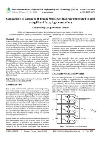
CascadedH-bridgeinverterisaseriesofH-bridgeinverter units. Each H-bridge is supplied with a dc source and the outputoftheinverterisaquasi-squarewaveformcontaining ,0and .Fora7-levelCascadedH-bridgeinverter, eachh-bridgecontainsaquasi-squarewaveformofdifferent timeintervalsandallthewaveformsareaddedupasshown intheFigure1.For11-levelCHBinverter,outputwaveforms offiveH-bridgeunitsareadded
Fig -1:SinglePhase7-levelCHB-MLI
International Research Journal of Engineering and Technology (IRJET) e-ISSN: 2395-0056
Volume: 09 Issue: 12 | Dec 2022 www.irjet.net p-ISSN: 2395-0072
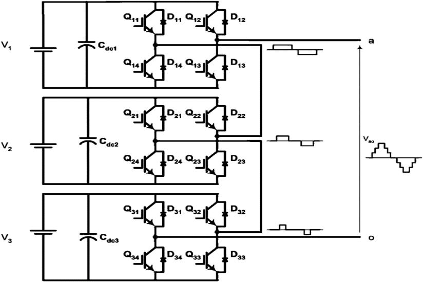
The number of output phase voltage levels in a cascaded multilevel inverterisdefinedasn=2m+1,where‘m’isthe numberofH-bridgeunitsorseparatedcsources.Thispaper presents a three phase cascaded multilevel inverter anda simulationmodelforasevenlevelinverterisshowninthe Figure2.
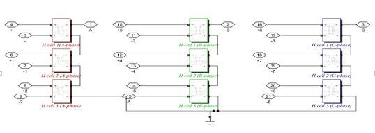
(Negative Small), ZE (Zero Error), PS (Positive Small), PB (PositiveBig))arecharacterizedbymembershipgradethat areusedtodecomposeeachvariableintofuzzyregions.
InthisPapertwoinputvariables(errorandrateofchangein error) and one output variable (control signal) is chosen. Figure4representsthelinguisticlabelofaninputvariable.
-4
Fig -2:ThreePhase7-levelCHB-MLI
AFuzzyLogicController(FLC)iseasytodesignanddoesnot requireadetailedmathematicalmodelofthesystembeing controlled.However,anunderstandingofthesystemandits controlrequirementsisnecessary.Thecontrollerdesigner must define what information flows into the system, informationprocessedandwhatinformationflowsoutofthe system. A FLC design consists of three important stages namelyfuzzifier,inferenceengineanddefuzzifier.
A set of rules are provided for control action and this functionisperformedininferencesystem.Adecisionmatrix tableusingtheinputandoutputvariablesisshowninthe Table 1. For example, if error voltage is NB and rate of change of error is NB, then the controller output is ZE. Similarly25rulesareformedfromthedecisionmatrixand each rule in the table is used to decide an appropriate controlaction.
Table -1: Decisionmatrix
C/CE NB NS ZE PS PB NB ZE NS NB NB NB NS ZE NS NB NS NS ZE PB PS ZE NS NB PS PB PS PS ZE NS PB PB PB PB PS ZE
Fig -3:CascadedMultilevelInverterwithFLC
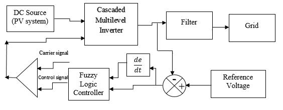
Firstly,theappropriateinputandoutputvariablesshould beselectedfordesigningafuzzylogiccontroller.Fuzzylogic uses linguistic variables for processing the information insteadofnumericvariables.Thefunctionofafuzzifieristo convertthesecrispsetsintolinguisticvariables(fuzzysets). Five classes of linguistic labels (NB (Negative Big), NS
The Linguistic variables (fuzzy sets) are converted into crispsolutionsetsthroughadefuzzifier.Thereareseveral methods of defuzzification. The most commonly used methodiscentroidmethodorcenterofarea(COA),asitis veryaccurate.Thecenterofareaisprovidedunderthecurve of membership function and it puts high demands on computationforcomplexmembershipfunctions.
International Research Journal of Engineering and Technology (IRJET) e-ISSN: 2395-0056
Volume: 09 Issue: 12 | Dec 2022 www.irjet.net p-ISSN: 2395-0072
The steady state error can be eliminated by using a PI controller but does not have ability to predict the future errors of the system. A cascaded H-bridge inverter connectedwithaPIcontrollerisshownintheFigure5
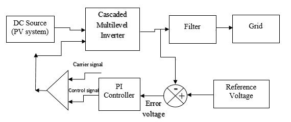
Fig -5:CascadedInverterwithPIcontroller
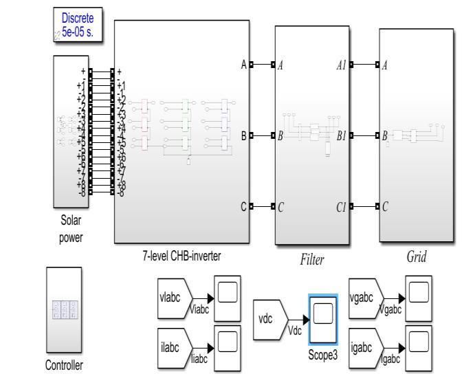
A Grid connected PV system is shown in the Figure 6. PV systemvoltageof220Visgiventotheinverter.ACascaded inverterusesaseparatedcsourceforeachH-bridge.Thus, thevoltagegiventoeachH-bridgeisgivenas
= Volts,‘m’isthenumberofH-bridgeunits.
AgridconnectedmultilevelinverterusingPIcontrolleris designed and the simulation results are provided. A PI controllerprovidesbetterperformanceundersteadystate butthedynamicperformanceisnotsatisfactory
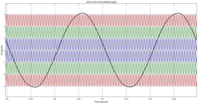
Sinusoidal pulse width modulation (SPWM) technique is widelyemployed.InSPWM,thecontrolsignalproducedby thecontrolleriscompared withthetriangularsignal asin Figure7andthepulsesaregenerated.Thispulses control theinverteroutputvoltage.
(a) (b)
International Research Journal of Engineering and Technology (IRJET) e-ISSN: 2395-0056
Volume: 09 Issue: 12 | Dec 2022 www.irjet.net p-ISSN: 2395-0072
(c)
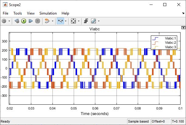
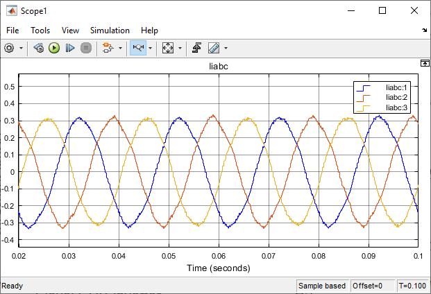
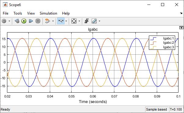
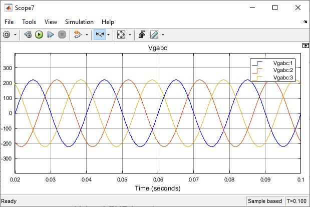
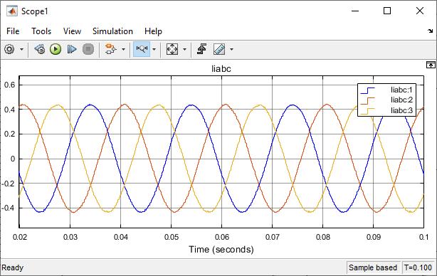
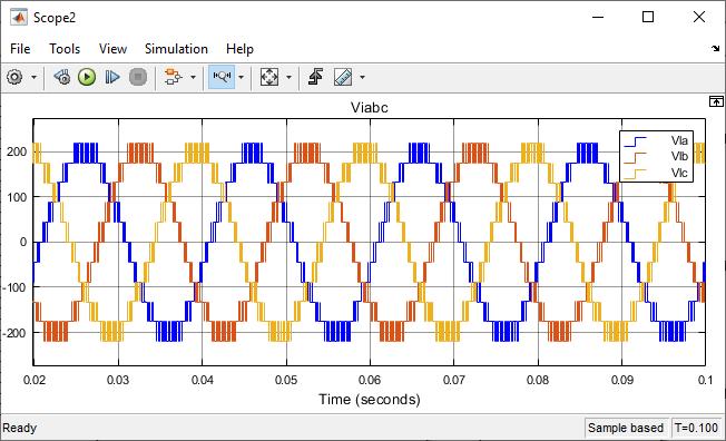
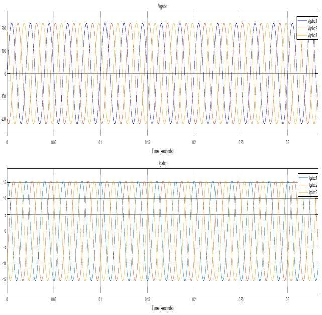
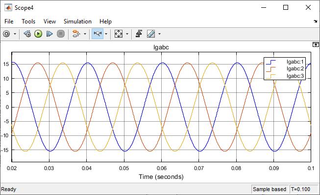
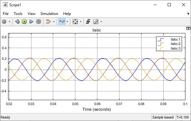
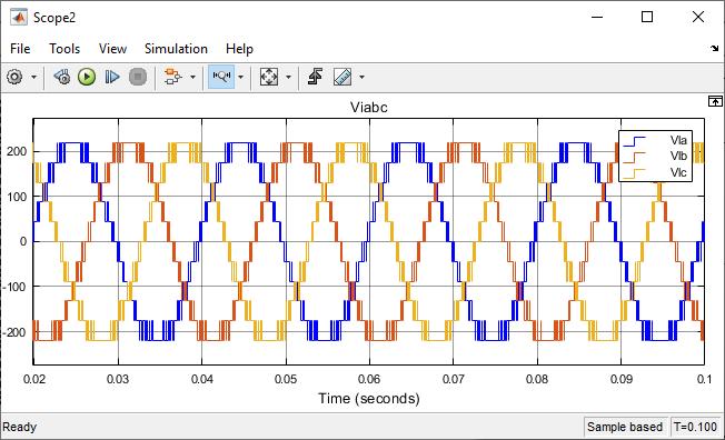
Fig -8:7-leveloutputwaveforms(a)Inverteroutput voltage( )(b)Inverteroutputcurrent( )(c)Grid voltage( )andgridcurrent( )(d)FFTAnalysis
(d)
InPIcontrollerKpandKivaluesareobtainedbytrialand errormethod.ThispaperusesaclosedloopPIcontrollerand theoutputwaveformsareshownintheFigure8and9.
(a) (b) (c) (d)
International Research Journal of Engineering and Technology (IRJET) e-ISSN: 2395-0056
Volume: 09 Issue: 12 | Dec 2022 www.irjet.net p-ISSN: 2395-0072
(e)
Fig -9:11-leveloutputwaveforms(a) (b) (c) (d) (e)FFTAnalysis
Fuzzylogiccontrollerusesmultipleinputcommandsand thus it is more accurate when compared to PI controller. Basedontheinformationcollectedarulebasedfuzzylogic controllerisdesignedinMatlab/Simulinkmodel. (a)
(b) (c) (d)
International Research Journal of Engineering and Technology (IRJET) e-ISSN: 2395-0056
Volume: 09 Issue: 12 | Dec 2022 www.irjet.net p-ISSN: 2395-0072
(e)
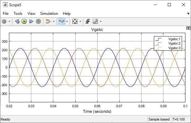
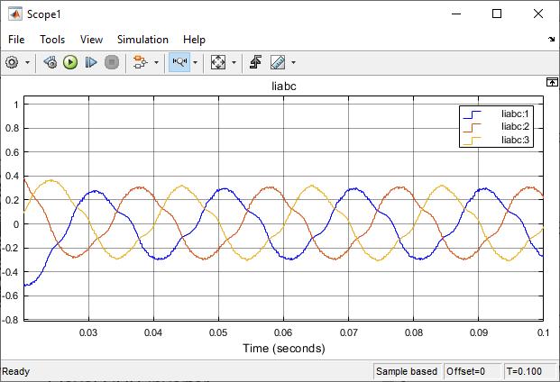
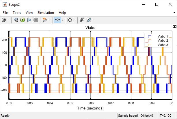
Fig -10:7-leveloutputwaveforms(a) (b) (c) (d) (e)FFTAnalysis (a)
(b)
In the Figure 6, a filter circuit is used to generate a distortion less voltage to the grid. The filter circuit RLC values selected based on the trial and error method. The obtainedvoltageisgiventogridandtheoutputvoltageand currentwaveformsusingarulebasedfuzzylogiccontroller isshownintheFigure10andFigure11.
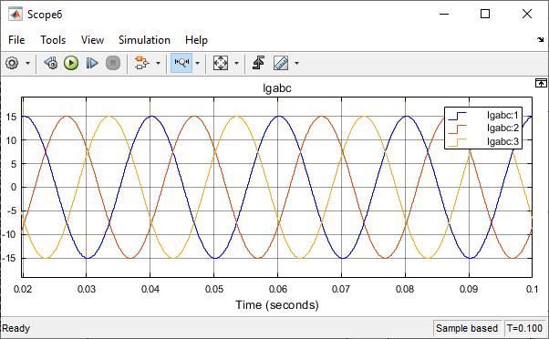

(c) (d)
International Research Journal of Engineering and Technology (IRJET) e-ISSN: 2395-0056
Volume: 09 Issue: 12 | Dec 2022 www.irjet.net p-ISSN: 2395-0072
issubstandard.Toimprovethesystemperformancearule based fuzzy logic controller is developed. The simulation results explores that a FLC performs better than a PI controller.FuzzylogiccontrollerofferslessTHDand good dynamic response under transient condition when comparedtoaPIcontroller.ThustheproposedMLIusing FLC is suitable where the periodic distortion problem is present.
[1] Towleong Tiang and Dahamen Ishak,‘’Modelling and simulationofdead beatbasedPIcontrollerinasingle phase H-bridge inverter for standalone applications’’, Turkishjournalofelectricalengineeringandcomputer sciences,22,pp43-56,2014
[2] B.Suryajitt,G.Sudhakar,”PowerQualityImprovement Using Cascaded H-Bridge Multilevel Inverter Based Dstatcom” Int. Journal of Engineering Research and Applications,ISSN:2248-9622,Vol.4,Issue11,pp.31-37, November2014.
(e)
Fig -11:11-leveloutputwaveforms(a) (b) (c) (d) (e)FFTAnalysis
Theabovediscussedresultsrevealthatfuzzylogiccontroller performsbetterthanPIcontroller.Afuzzylogiccontrolleris moreaccurateduetothemultipleinputcommandandalso performs better during the dynamic conditions. The performance of 7-level and 11-level cascaded H-bridge inverter with PI controller and fuzzy logic controller is analysed and the results were tabulated. Output voltage qualityismeasuredinTHD.
Table -2: Comparisontable
THD PI Fuzzylogic 7-level 17.08% 15.60% 11-level 12.89% 10.94%
Hence,itcanbeconcludedthattheTHDisreducedwhenthe inverter level is increased and better reduced by using a fuzzylogiccontrolleroveraPIcontroller
Increase in inverter level always reduce THD but the dynamic response of the system needs to be improved. MultilevelinverterwithaclosedloopPIcontrollerimproves thesteadystateresponsebutstillthedynamicperformance
[3] B. Shanthi, S.P. Natarajan, ‘’FPGA based fuzzy logic control for single phase multilevel inverter’’ International Journal of Computer Applications, vol.9, no.3,pp10-18,Nov2010
[4] JorgeLuisDiazRodriguez,LuisDavidPabon,AldoPardo Garcia,”THDimprovementofaPWMcascademultilevel power inverters using genetic algorithms as optimization method” WSEAS TRANSACTIONS on POWERSYSTEMS,Volume10,pp46-54,2015
[5] O. M. Toledo, D. O. Filho, A. S. A. C. Diniz, “Distributed photovoltaicgenerationandenergystoragesystems:A review,”RenewableSustainableEnergyRev.,vol.14,no. 1,pp.506–511,2010
[6] Gupta,K.K.;Jain,S.;"Topologyformultilevelinvertersto attain maximum number of levels from given DC sources,"PowerElectronics,IET,vol.5,no.4,pp.435-446, April2012
[7] AsgharAbedini,SalaheddinZabalawiandAdelNasiri,“A three-phase uninterruptible power supply with an adaptivereferencewaveformgenerator”,Int.J.Power Electronics,Vol.1,No.1,pp.63-86,2008.
[8] L. G. Franquelo, J. Rodriguez, J. I. Leon, S. Kouro, R. Portillo,M.A.M.Prats,“Theageofmultilevelconverters arrives,”IEEETransonIndus.Electronics,vol.2,no.2, pp.28–39,Jun.2008