International Research Journal of Engineering and Technology (IRJET) e-ISSN:2395-0056

Volume: 09 Issue: 12 | Dec 2022 www.irjet.net p-ISSN:2395-0072
International Research Journal of Engineering and Technology (IRJET) e-ISSN:2395-0056
Volume: 09 Issue: 12 | Dec 2022 www.irjet.net p-ISSN:2395-0072
S.Dave1, Dr. B.S More2
1M.Tech. Scholar, Dept. of Mechanical Engineering, Shri Govindram Seksaria Institute of Technology And Science,Indore, Madhya Pradesh, India
2Associate Professor, Dept. of Mechanical Engineering, Shri Govindram Seksaria Institute of Technology And Science,Indore, Madhya Pradesh, India ***
Abstract
Since the discovery of Kármán vortex streets, flow around bluff bodies has garnered a lot of investigation. Studying the vortex behaviour, the distribution of velocity and pressure on body are very important from a practical standpoint. Analysing the unsteady wake behind the body of circular and square geometries has been the subject of in-depth research using numerical techniques like computational fluid dynamics (CFD), in order to forecast the resulting pressure and velocity field around the body..The flow around stationary circular and rectangular/square cylinders has been the subject of extensive study.In contrast to that, only a small amount of research has been done on the flow zone behind hexagonal cylinders. The vortex behaviour including lift,drag and vortex frequency analysis of the 2D hexagon are thesubjectsofthisstudy.
Key Words – Reynolds Number, Strouhal Number, Strouhal Frequency, Vortex Shedding , Lift, Drag
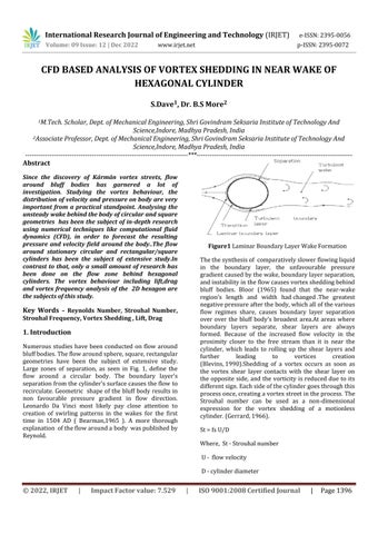
Numerous studies have been conducted on flow around bluffbodies.Theflowaroundsphere,square,rectangular geometries have been the subject of extensive study. Large zones of separation, as seen in Fig. 1, define the flow around a circular body. The boundary layer's separationfromthecylinder'ssurfacecausestheflow to recirculate.Geometric shapeofthe bluffbody resultsin non favourable pressure gradient in flow direction. Leonardo Da Vinci most likely pay close attention to creation of swirling patterns in the wakes for the first time in 1504 AD ( Bearman,1965 ) A more thorough explanation oftheflowaroundabody waspublishedby Reynold.
Thethesynthesisof comparativelyslowerflowingliquid in the boundary layer, the unfavourable pressure gradientcausedbythewake,boundarylayerseparation, andinstabilityintheflowcausesvortexsheddingbehind bluff bodies. Bloor (1965) found that the near-wake region's length and width hadchanged.The greatest negativepressureafterthebody,whichallofthevarious flow regimes share, causes boundary layer separation over over the bluff body's broadest area.At areas where boundary layers separate, shear layers are always formed. Because of the increased flow velocity in the proximity closer to the free stream than it is near the cylinder, which leads to rolling up the shear layers and further leading to vortices creation (Blevins,1990).Shedding of a vortex occurs as soon as the vortex shear layer contacts with the shear layer on the opposite side, and the vorticity is reduced due to its differentsign.Eachsideofthecylindergoesthroughthis processonce,creatingavortexstreetintheprocess.The Strouhal number can be used as a non-dimensional expression for the vortex shedding of a motionless cylinder.(Gerrard,1966).
St=fsU/D
Where, St-Strouhalnumber
U- flowvelocity
D-cylinderdiameter
International Research Journal of Engineering and Technology (IRJET) e-ISSN:2395-0056
Volume: 09 Issue: 12 | Dec 2022 www.irjet.net p-ISSN:2395-0072
fs-frequencyof vortexshedding.
Reynolds number influences how frequently vortices shed in the wake of a cylinder., according to earlier experimentalfindings(SumerB.M.,2006)
VonKarmanVortex:-Thedragandliftforceexertedby the fluid on the cylinder, are often separated. Reynolds numbers above 40 cause the flow to oscillate and cause vortexshedding.Becauseoftheperiodicvariationinthe pressure field surrounding the bluff bodies, the force components also start to follow a predictable pattern. The drag and lift forces can be further separated into mean and fluctuation parts for analytical reasons. Whearas meandragcoefficientCD variesaboutitsmean value and has a fixed value. In contrast, the mean Force of lift varies around 0 and mean lift coefficient CL is nil andvariesveryless.
The drag force will exert its influence on the cylinder surfaceintheflowdirectionaccordingonthesize,shape, and orientation of the bluff body. The relationship between the drag force and fluid velocity is defined by thedragcoefficientCD,whichisprovidedby:
Cd=2���� L/ρLU2D
Where,⍴-fluiddensity, U–velocityoffluidflow, D–diameterofcylinderbody, L-lengthofcylinderbody ���� - dragforce
Furthermore, CL, the lift coefficient, is computed similarly,butitalsotakesintoaccounttheforceactingin the direction perpendicular to that of the flow. The lift force,abbreviatedFL,is wordusedtodescribetheforce thatcorrespondstothecross-flowdirection.
Cl=2��L L/ρLU2D
Where⍴- fluiddensity U- velocityoffluidflow, D-diameterofcylinderbody, L-lengthofcylinderbody ���� –liftforce
Khaledi and Andersson (2011) investigated the vortex structure underlying hexagonal cylinders with faces and corners. Although the small disturbed vortex structures
and the vorticity with extremely erratic flow patterns were downstream of the hexagonal cylinder, subcritical Reynolds numbers allowed for visualisation of the turbulent flow's characteristics. However, there weren't many distinctions between corner orientation and face orientation vortex structures when compared downstream(Khaledi&Andersson,2011).
Skyscraping buildings, tunnel that float, and frames that support prototype for testing in wind tunnel are a few examples of engineering issues that frequently include polygonalcross-sectionwithN ≥3[Nreferstonoofside ].Unfortunately,theliteratureoncylinderwithN>4has received far less attention than that on the circular cylinder wake, and the relevant data are rare. The previously recorded data for square and rectangular cylinder are used with approximation whenever new problems regarding cylinder with N > 4 is faced. Even under the identical flow conditions, as will be shown in thisstudy,thefluidparametersassociated withcylinder with N> 4 might change dramatically from those associated with a circular or square cylinder in some situations,makingthismethodexceedinglydangerous.
Re =ρVL/μ
St =FstL/Uo
Re=ReynoldNumber
St=Strouhalnumber
ρ= Densityoffluid
μ= DynamicViscosityoffluid
L=CharacteristicLength
Uo=velocityoftheambientflow
Fst = StrouhalFrequency
Wehaveconsideredtheflowacrosscylinderwithcorner oriented hexagonal cross-section. All sides of polygon are measured L with all interior angles measuring 120 degree. Corner orientation is considered as show in figure2.Thecylinderwaslocated20Lfromvelocityinlet boundary and 60L from pressure outlet boundary, with cartesian coordinates of the system located at centre of thecylinder.
International Research Journal of Engineering and Technology (IRJET) e-ISSN:2395-0056
Volume: 09 Issue: 12 | Dec 2022 www.irjet.net p-ISSN:2395-0072
Strouhal Number
Figure 2 Schematicofcomputationaldimensionfor studyingtheflowpasthexagonalcylinder
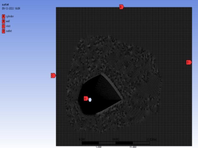
The ANSYS 2022R2 student version is used to complete the mesh generation. This software generates finiteelement grids in three dimensions and is open-source. For Re =100,500 , and 1000, the computational domain is discretized into 143505 grid cells. Six distinct mesh types were examined for the grid independence test. Making our mesh finer may produce different results when we start with a coarse mesh and solve. However, there is a point beyond which, no matter how fine we make it, we won't see any differences in the outcomes. We can then claim to have attained grid independence. The mesh will now be fine enough to record even the mostminuteaspectsoftheflow.
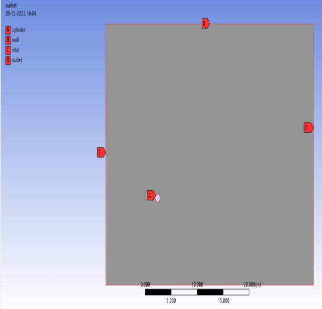
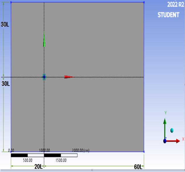
Figure 3 MeshedModelusedinthisstudy
0.1716 0.1717 0 0.02 0.04 0.06 0.08 0.1 0.12 0.14 0.16 0.18 0.2 0 50000 100000 150000 200000
0.12124 0.13458 0.15874 0.1698
No Of Elements
Chart 1 VariationofStrouhalnumberwithnumberof elementsinmesh
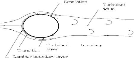
The direction of fluid flow is in the positive X-direction, i.e from left to right. There is a specified uniform inflow velocity u =u0 selected in accordance with the Reynold number .After that, the system is resolved utilising the formulas of (SST k-) turbulence model. The NavierStokes equations in 2D incompressibility are the governing equations. The computational domain identifiestheamorphoussettinginwhichthesolutionis computed.Itismadeupofawall,ahexagonalcylinder,a velocityentrance,andapressureoutlet.
Density-1kg/m³; Viscosity-1kg/m-s
Figure 4 Schematicofboundaryconditionsforstudying theflowpasthexagonalcylinder
International Research Journal of Engineering and Technology (IRJET) e-ISSN:2395-0056
Volume: 09 Issue: 12 | Dec 2022 www.irjet.net p-ISSN:2395-0072
Based on the mesh grid sensitivity result and validation ofpresentmeshresult with thatofKhaledi Andersson work,themeshwith143505gridelements wasselected forpresentstudy.
Sr. No Cylinder Type Reynold Number Khaledi & And ersson [2011]St
Present Work [2022]St
1 Hexagonal 100 0.1585 0.1594
2 Hexagonal 500 0.1718 0.177
3 Hexagonal 1000 0.1718 0.175
Table 1 ComparisonofStrouhalnumberofpresentwork withpublishedwork
The dimensionless coefficients Cd and Cl are used to quantify the drag coefficient and lift coefficient respectively. Graph 2 and 3 shows the variation of drag with Reynold number and variation of lift with Reynold number respectively. An increase in drag and lift coefficient could be evidently seen with an increase in Reynoldnumber.
Reynold Number Vs Drag Coefficient
Drag Coefficient
1.65
Lift Coefficient
Reynold Number vs Lift
1.408 0 0.2 0.4 0.6 0.8 1 1.2 1.4 1.6 0 500 1000 1500
0.1242 0.1971
Reynold Number
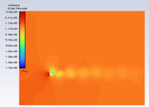
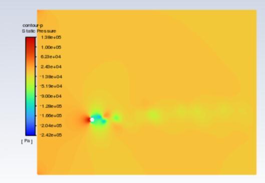
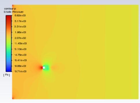
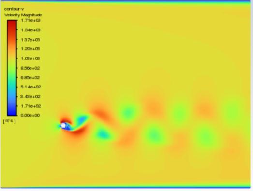
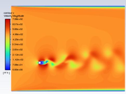
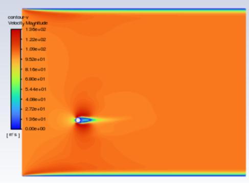
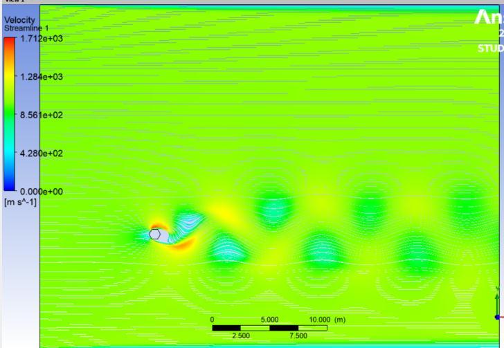
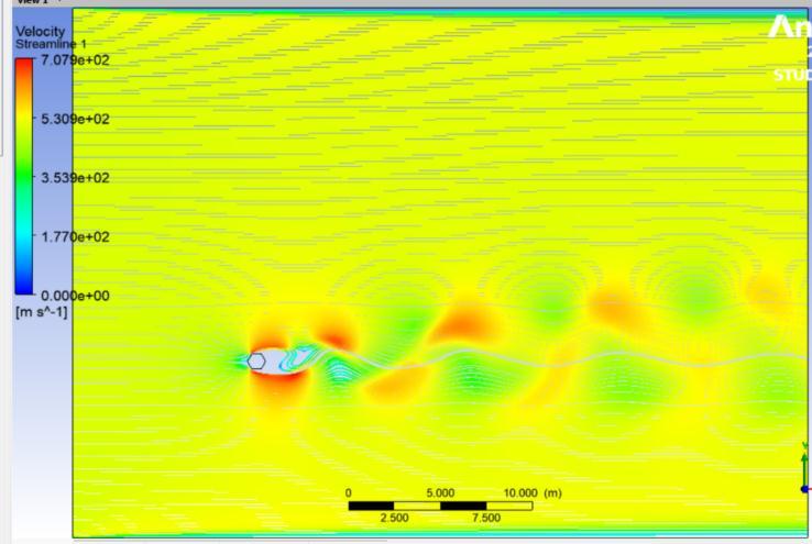
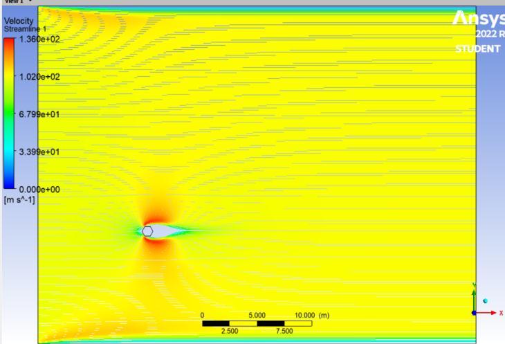
The velocity contours are represented in figures 5 to 7 , whereas pressure contours are represented in figures 8 to 10 . When used to visualise the flow in 2D, velocity contours make it simple to grasp how the air is moving around the cluster of cylinders and how its velocity is changing The pressure contour allows one to comprehend the coefficient of pressure distribution visually. for the hexagonal cylinder for Re =100,500 and 1000respectively. Accordingtothescaleon theleft, the colours red and orange denote higher pressure, while the colours green, yellow, and blue denote relatively lowerpressurezones.
1.55
1.45
1.6
1.5
1.6842 1.4
1.7 0 500 1000 1500
Fig.5 illustratesthatthebaseregion'sgeneratedvortices are alternatively shed and build a laminar vortex street with a Karman-like structure throughout the flow domain. However, at Re equal to 500, the flow-parallel faces appear to be the location where the shear layers appear to divide. And as Reynold number is increased furthercompleteturbulenceinwakecouldbemarked. 1.4444
1.51
Reynold Number
International Research Journal of Engineering and Technology (IRJET) e-ISSN:2395-0056 Volume:
International Research Journal of Engineering and Technology (IRJET) e-ISSN:2395-0056
International Research Journal of Engineering and Technology (IRJET) e-ISSN:2395-0056
Volume: 09 Issue: 12 | Dec 2022 www.irjet.net p-ISSN:2395-0072
formulationwasbasedonSSTk-ωmodel Andwefound a significant increase in shedding frequency with increase in Reynold number and also with increasing Reynolds number, a significant rise in Strouhal number wasmarked.
1]BLOOR,M.S.1965.Thetransitiontoturbulenceinthe wake of a circular cylinder. Journal of Fluid Mechanics, 19,290
2]ZDRAVKOVICH, M. M. 1997 Flow Around Circular Cylinders,vol.1.OxfordUniversityPress.
3] FEY, U., KÖNIG, M. & ECKELMANN, H. 1998. A new Strouhal–Reynolds-number relationship for the circular cylinder in the range 47. Physics of Fluids, 10, 15471549.
4] SOHANKAR, A., NORBERG, C. & DAVIDSON, L. 1998. Low‐Reynolds‐number flow around a square cylinder at incidence: study of blockage, onset of vortex shedding and outlet boundary condition. International journal for numericalmethodsinfluids,26,39-56
5] SUMER B.M., F. J. 2006. Hydrodynamics around cylindrical strucures, World Scientific Publishing Co Pte. Ltd.Singapoe.
6] VADA, T., NESTEGRD, A. & SKOMEDAL, N. 1989. Simulation of viscous flow around a circular cylinder in the boundary layer near a wall. Journal of fluids and structures,3,579-594
7] TIAN, Z. W. & WU, Z. N. 2009. A study of twodimensional flow past regular polygons via conformal mapping.JournalofFluidMechanics,628,121-154.
8] KHALEDI, H. A. & ANDERSSON, H. I. 2011. On vortex shedding from a hexagonal cylinder. Physics Letters A, 375,4007-4021.