International Research Journal of Engineering and Technology (IRJET) e-ISSN:2395-0056

Volume: 09 Issue: 12 | Dec 2022 www.irjet.net p-ISSN:2395-0072
Comparative Computational analysis of performance parameters for shell and tube heat exchanger using helically twisted insert and SIO2 nanofluid
Bhanu Pratap Research Scholar, Department of Mechanical Engineering Trinity Institute of Technology and Research Bhopal, India
Abstract Exergy balance aspects are always a prime concern encountered in the thermal engineering field face. Present research deals with the study of a concentric shell and tube heat exchanger performance parameters i.e. heat transfer rate using Nanofluid and a geometry change as compared to base fluid. Based on the experimental model of the research under consideration, the numerically validated results of a virtual shell and tube heat exchanger satisfies model used for present study. Using same conditions under the research considered the system is provided with liquids that are both hot and cold, with temperatures of 343K and 303K, respectively. When using water as the working fluid, readings were observed at a flow rate ranging from 0.05 kg/s to 0.2 kg/s for the cold fluid. The nanofluid made of SiO2 nanoparticles instead of water as the working fluid for the same analysis was also carried out under the identical boundary conditions. For the best results, this nanofluid's volume fraction was varied and calculated. The same calculations were carried out for this system using the nanofluid with a volume fraction of 0.4. The obtained results demonstrated that SiO2 nanofluid significantly improves performance. On the other hand, in order to increase the heat transfer coefficient by causing turbulence in the flow of hot fluid, a geometrical change in the form of a helical insert is made. The insert has an effective length of 950 mm and a pitch length of 2.5 inches. For each of the three scenarios, performance parameters like maximum heat transfer rate, overall heat transfer coefficient, and LMTD are calculated and compared. Performance Evaluation Criterion is also evaluated which provides the relative improvement of heat transfer rate w.r.t the additional power loss for creating that turbulence. Scatter plots show that the effectiveness of the heat exchanger is improving.
Keywords heat exchanger, CFD analysis, nanofluid,SiO2,solidworks,helicalinserts
Rohit Soni Asst. Professor, Department of Mechanical Engineering Trinity Institute of Technology and Research Bhopal, India
1. INTRODUCTION
Usingaheatexchanger,heatenergycanbetransferred from one fluid to another that is in direct or indirect contact with one another. Heat exchangers are used in a widevarietyofcommercialandindustrialsettings.boilers, air coolers, chilling towers, evaporators, condensers, etc. Additionally, autos employ heat exchangers in the form of radiators, intercoolers, and oil coolers inside engines. Additionally,heatexchangersarefrequentlyutilizedinthe chemical and process industries to transfer heat between twofluidsthatareinonestateortwostates.:[1]
1.1.AccordingtoTypeofcontact
1.DirectContactType 2.TransferTypeHeatExchanger 3.RegenerationtypeHeatExchanger
1.2.Accordingtoshapes 1.TubularHeatExchanger 2.ShellandTubeHeatExchanger 3.FinnedtubeHeatExchanger
1.3.Accordingtodirectionofflowoffluids 1.Parallelflow 2.Counterflow 3.Crossflow
1.4HeatTransferEnhancement
The improvement of heat transfer rate is one of thekeyconsiderationsinthedesignofaheatexchangerin order to make the heat exchanger for mechanical and chemical devices and plants more and more compact. Techniques for improving heat transfer are often divided into two categories. As can be observed, the rate of heat transferinturbulentflowisalwayshigherthantherateof heat transfer in laminar flow. By creating turbulence in a fluid flow, the rate of heat transfer can be increased. The geometric heat transfer coefficient (general heat transfer
International Research Journal of Engineering and Technology (IRJET) e-ISSN:2395-0056
Volume: 09 Issue: 12 | Dec 2022 www.irjet.net p-ISSN:2395-0072
coefficient) depends on a number of factors, including the orientation of the heat exchanger, its geometry, the characteristics of the fluid flow, the kind of fluid (such as turbulent or laminar), the material of the tube, etc. Two thingscancauseturbulence[2]
1.5NANOFLUIDS:
The four essential properties of a base fluid density, viscosity, thermal conductivity, and specific heat are enhanced by the presence of nanosized particles of either metal oxides or carbides in a nanofluid. These improvement in properties permit liquid to move more intensity in contrast with the base liquid. Silicon dioxide (SiO2)isthenanoparticleusedinourstudy.Itsproperties arecalculatedandshowninTable1 [3]
2. INTRODUCTION TO SOLIDWORKS
Solidworks is a product utilized for virtual displaying and investigation of frameworks utilized for designing plans. Dassault Systems produced it. The software tool primarily serves to represent design through virtual modeling. Software analysis is available for determining optimal values.
2 1 STEPS FOR SOLVING A GENERAL PROBLEM IN SOLIDWORKS:
Similar to solving any problem analytically, you need to define (1)problemdomain, (2)Virtualmodel, (3)Boundaryconditionsand (4) Physicalproperties.
Youthenpresentyoursolutiontotheproblem.Intermsof numbers, an additional step known as mesh generation makes the most difference. This is the step that breaks up theadvancedmodel intosmallerpiecesthatcanbesolved inanAssociateinNursingscenarioifitisnottooadvanced. The procedures are described below in word with slight adjustmentsforthesoftwaresystem.[4]
2.1.1 Virtual Modelling
Utilizing the work plane coordinate system in Flow simulation-SOLIDWORKS, create a two- or threedimensional virtual model of your project for the object's representationandtestit.
2 1.2 Assigning material
Create a list of necessary materials that make up the modelled item (or project) now that the part has been modeled.Mechanicalandthermalpropertiesareincluded.
2.1.3
Generate Mesh
SOLIDWORKS knows the part's composition at this point. Now, specify how the Modeled System should be broken down into smaller, more manageable pieces in order to calculate an infinitesimal object. The system will use the iterative method to combine the results for the entire System.
2.1.4 Problem set-up
The final step is to set the system up with constraints like physical loadings or boundary conditions after it has been fully designed. In this section, we will provide the fluid's flowrates,theeffectofgravity,andthekindofdifferential equationonwhichtheproblemisbased.
2.1.5 Generate Solution
In this case, the software needs to know what kind of analysis it needs to do steady state or transient. In addition, the software performs a sample of ten iterations to determine whether the solution will converge to a uniquevalue.
2 1.6 View Results/Reports (post Processing)
Theprocessofobtainingthesolutioninthedesiredformat isknownaspostprocessing.Youhaveavarietyofoptions for how the solution can be presented in SOLIDWORKS, includingtables,graphs,andcontourplots[5]
3. METHODOLOGY
3.1 CFD PROCESS ANALYSIS:
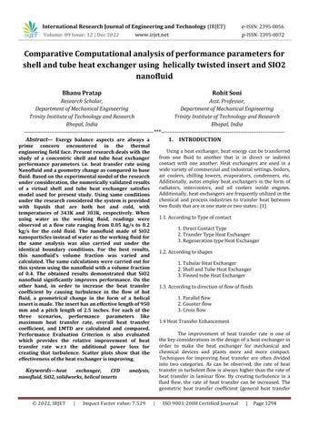
SOLIDWORKS 22 software is used to simulate the results, and a Computational Fluid Dynamics (CFD) analysisiscarriedouttoverifythe results.Thesimulation iscarriedoutasdepictedinfig.1,ablockdiagram.[6]
© 2022, IRJET | Impact Factor value: 7.529 | ISO 9001:2008 Certified Journal | Page1295
International Research Journal of Engineering and Technology (IRJET) e-ISSN:2395-0056
Volume: 09 Issue: 12 | Dec 2022 www.irjet.net p-ISSN:2395-0072
discovered for this arrangement. Additionally, various volumefractionvaluesofthenanofluidareexamined,and the most appropriate volume fraction is used in the calculations.
6. The heat transfer rate, LMTD, overall heat transfer coefficient, and heat exchanger efficiency are used to comparetheoutcomes.
7. A helically twisted insert of pitch length 2.5-inch has been placed inside the inner tube of shell and tube heat exchanger. The insert has been placed in order to create turbulenceintheflowoffluid,whichinturnsincreasethe valueofheattransfercoefficientresultinginimprovement of performance of heat exchanger. The geometric parameters and fluid parameters oof the system is kept sameasitwereinsimpleshellandtubeheatexchanger.
8. Performance Evaluation Criterion is calculated between simple heat exchanger and helically inserted heat exchanger,tojustifytheuseofinserts.
Fig1CFDProcess[7]
3.2 COMPUTATIONAL PROCEDURE:
1. In SolidWorks 2022, a virtual concentric shell and tube heat exchanger can be virtually designed. The experimental base paper's dimensions apply to the heat exchanger.
2.Theinnertubehasadiameterof12millimetersandthe outertubehasadiameterof14millimeters,whiletheshell hasa diameterof17millimetersandanouterdiameter of 18millimeters,respectively.
3.Copperisthematerialthatwasusedtomakebothofthe tubes, and it has the same properties at any temperature. Themassflowrateofhotfluidflowingthroughtheannuus of both tubes is kept constant at a value of 0.05kg/s, whereas the mass flow rate of cold fluid flowing through theannulusisvariedfrom0.05kg/s,0.1kg/s,0.15kg/s,and 0.2kg/s, respectively. The inlet temperatures of the cold fluidarekeptat303Kandtheinlettemperatureofthehot fluidiskeptat343K.
4.Ourfoundationalpaper'sexperimentalfindingsserveas validation for this virtual model's initial designs. Heat transfer rate, effectiveness, and LMTD values are calculated and presented for the water-water heat exchangerresults.
5.ThepropertiesofaNano-Fluidaredeterminedusingthe aforementionedstandardformulasinvirtualsoftware.The viruswatercoursingthroughannulusissupplantedbythis nano liquid while keeping the gulf temperature and its mass stream rate same. The calculations are also
4 MATHEMATICAL AND ANALYTICAL PROCEEDURE
4.1 Calculation of Properties of nanofluid
As discussed above, the nanofluid is considered on 4 differentpropertiesoffluid.Theyarecalculatedasfollows: [8]
4.1.1.
Volume Fraction:
ANano-Fluidismadeupofasolutionofadissolvingliquid, and nano particles of any suitable metal, oxides or carbides. The concentration of these particles in this base fluidisofimportance becauseit changesthepropertiesof nanofluid.
4.1.1.
Density of Nano Fluid:
Duetotheadditionof two different densitiesofmaterials, the resultant density of solution changes and it can be calculatedasshown.
Where,
ρnf:Densityofnanofluid.
Φ:VolumeFraction
ρw:Densityofwater
ρs:Densityofsolid
© 2022, IRJET | Impact Factor value: 7.529 | ISO 9001:2008 Certified Journal | Page1296
International Research Journal of Engineering and Technology (IRJET) e-ISSN:2395-0056
4.1.2. Specific heat of nano fluid:
This is the net heat that one kg of nano fluid will be requiringinordertoraiseitstemperatureto1K.
Where, Cp(nf):Specificheatofnanofluid
4.1.3 Viscosity of nano fluid:
Thisistheresistancetoflowthatiscausedbyshearstress inthenanofluid.
where, µ(nf):DynamicviscosityofnanoFluid.
4.1.4 Thermal conductivity of Nano Fluid: 4.1.5 Performacne
parameters of Heat exchanger
A. Heat Transfer Rate: Heat Transfer Rate of Hot Fluid:
As the inlet and outlet temperature of both the fluids are knownthen,wecanfindouttherateofheattransferofhot fluidbythefollowingexpression.
B.
Q=mcCp(Tco–Tci)
Heat Transfer Rate of Cold Fluid:
With the help of the temperatures of cold fluid inlet and outlet we can find out the heat gained by cold fluid by the followingexpression.
Q=mhCp(Thi–Tho)
The heat gained by cold fluid must be exactly equal to the heat lost by the hot fluid in fully adiabatic boundary condition. But since the surface cannot be fully adiabatic thus,weconsiderrateofheatlossbyhotfluidastheactual heattransferrateofthesystem.
C. Logarithmic Mean Temperature Difference:
At different section along the length of circular tubes the temperature difference between hot fluid and cold fluid willbedifferent,asthehotfluidwillcontinuouslybelosing heat to cold fluid. Logarithmic mean temperature
difference is the equivalent temperature difference which can be used to calculate heat transfer rate of the heat exchangerifitissubstitutedinthegeneralequationofheat transfer in Heat exchanger. We find out the logarithmic mean temperature difference for every case by using the followingexpression. Where,
=T1 (Hotfluidinlettemperature)–T4 (Coldfluidexit temperature)
=T2 (Hotfluidexittemperature)–T3 (Coldfluidinlet temperature)
=Logarithmicmeantemperaturedifference.
D. Overall Heat Transfer Coefficient:
The overall heat transfer coefficient is a measure of the overall ability of a series of conductive and convective barriers to transfer heat. It is commonly applied to the calculation of heat transfer in heat exchangers, but can be appliedequallywelltootherproblems.
Forourcaseofheatexchanger,sincewealreadyknowthe value of heat transfer rate thus we can use the following equation to determine the value of Overall Heat Transfer Coefficient.
U=Overallheattransfercoefficient(Watts/m2K).
E. Effectiveness of Heat Exchanger:
Volume: 09 Issue: 12 | Dec 2022 www.irjet.net p-ISSN:2395-0072 © 2022, IRJET | Impact Factor value: 7.529 | ISO 9001:2008 Certified Journal | Page1297
Itisadimensionlessparameteranddefinedastheratioof actual heat transfer rate ' by heat exchanger to maximumpossibleheattransferrate 'itisdenoted by'ε'.
Thevalueofeffectivenessoftheheatexchangercanalsobe determined for each case by using the following expression.[9][10][11][12]
International Research Journal of Engineering and Technology (IRJET) e-ISSN:2395-0056
Volume: 09 Issue: 12 | Dec 2022 www.irjet.net p-ISSN:2395-0072
F. Performance Evaluation Criterion:
This expression gives us the increase in heat transfer rate w.r.t. to the additional input power required for gaining thatenhancementinheattransferrate.
PEC=Improvementinheattransfer/additionaldropin pressure
5. Results
5.1 Properties of SiO2 Nano Fluid as calculated based on above formula
Calculations are made on the nano fluid properties that must be entered into SolidWorks software. The density of thenanofluid,itsspecificheat,itsviscosity,anditsthermal conductivity are the four essential properties. For each of the flow rates of 0.05, 0.1, 0.15, and 0.2 kg/s, the aforementioned calculations were performed for the volumefractionsof0.4and0.3,respectively.

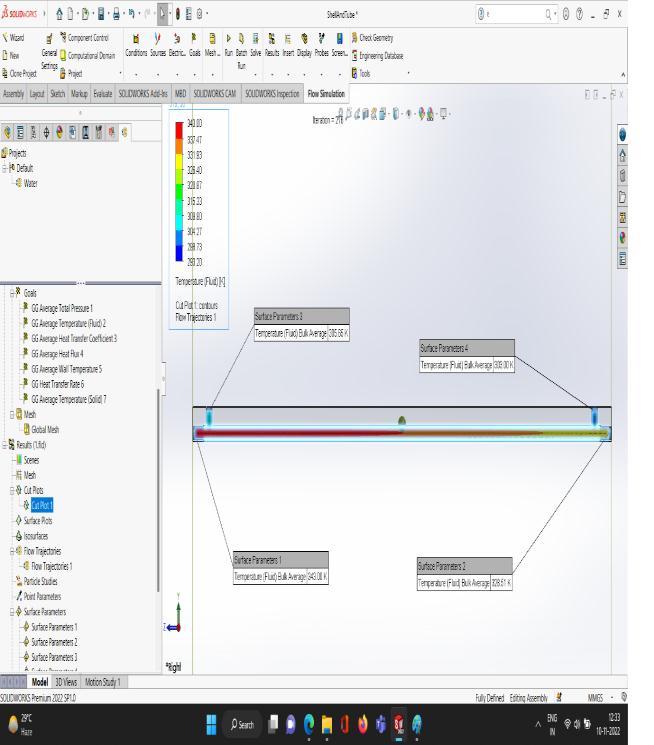

Table 1: Properties of Nano Fluid
NanoFluidPropertyTable
S.No mfC (kg/s) Volume Fraction mf(Nanoparti cleinkg/S)
Densityof SiO2Nano Fluid Knf(W/mK)
SpecificHeatof NanoFluid(J/kg-K)ViscosityofNanoFluid
1 0.05 0.4 0.08860 1658.2 1977.121819 0.002 1.259864
2 0.05 0.3 0.05696 1492.9 2346.076294 0.00175 1.034068
3 0.1 0.4 0.17720 1658.2 1977.121819 0.002 1.259864
4 0.1 0.3 0.11391 1492.9 2346.076294 0.00175 1.034068
5 0.15 0.4 0.26580 1658.2 1977.121819 0.002 1.259864
6 0.15 0.3 0.17087 1492.9 2346.076294 0.00175 1.034068
7 0.2 0.4 0.35440 1658.2 1977.121819 0.002 1.259864
8 0.2 0.3 0.22783 1492.9 2346.076294 0.00175 1.034068
5.2 Generated Report:
Fig2FrontViewofModeloftheShellandTubeHeat Exchanger

Fig3SideViewofShellandTubemodel
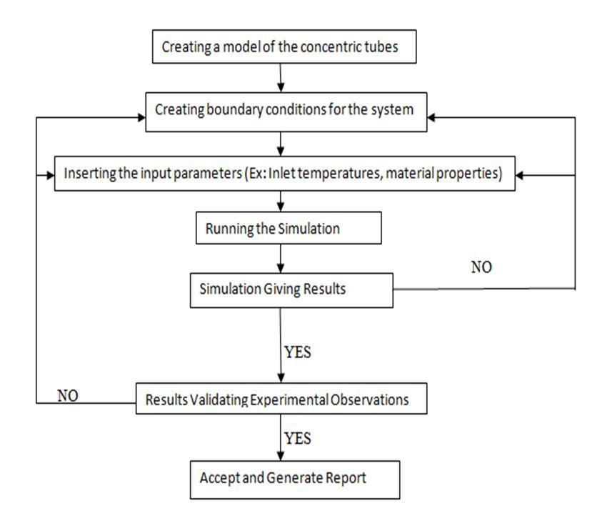
Fig4OutletTemperature(incaseofwater-waterheat exchanger)asdisplayedbysoftware
Fig5FlowTrajectoriesofTemperatureofHotFluid flowinginsidethetubeonaClipplane
International Research Journal of Engineering and Technology (IRJET) e-ISSN:2395-0056

Volume: 09 Issue: 12 | Dec 2022 www.irjet.net p-ISSN:2395-0072
Fig6OutletTemperature(incaseofwater-Nano-Fluid heatexchanger)asdisplayedbysoftware


Fig8(b)Assemblyofhelicalinsertinshellandtubeheat exchanger
Fig7FlowTrajectories(Water-Nano-Fluid)flowinginside thetubeonaClipplane
Fig9(a)CloseviewofFlowTrajectories(Water-waterhelicalinsert)flowinginsidethetubeonaClipplane
Fig8(a)Virtualmodelofhelicallytwistedshapedinsert

Fig9(b)FlowTrajectories(Water-water-helicalinsert) flowinginsidethetubeonaClipplane

International Research Journal of Engineering and Technology (IRJET) e-ISSN:2395-0056
Volume: 09 Issue: 12 | Dec 2022 www.irjet.net p-ISSN:2395-0072
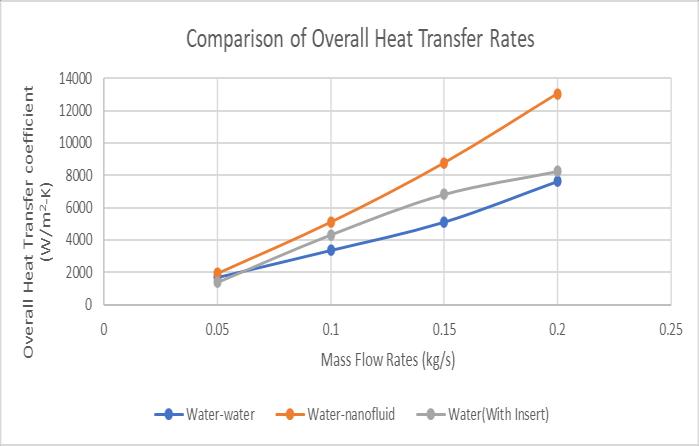
5.4 Comparison of Overall Heat Transfer coefficient based on Computational analysis
Theoverallheattransfercoefficientsofconcentriccircular plane tubes with and without inserts, in the water-water arrangement and the water-nanofluid arrangement, respectively, are compared in Figure 12. The comparison reveals that, for the same flow rates, the water-nanofluid arrangement achieves a value of 13039.99291 (Watts/(m2-K)) for the overall heat transfer coefficient, whereas the water system with helical insert achieved a valueof8254.945(Watts/(m2-K)).
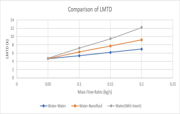
5.5 Comparison of LMTD based on Computational analysis of all the cases
Fig10OutletTemperature(incaseofwater-water-helical insertheatexchanger)asdisplayedbysoftware

5.3 Comparison of Heat Transfer Rate of water heat exchanger with nano-fluid heat exchanger.
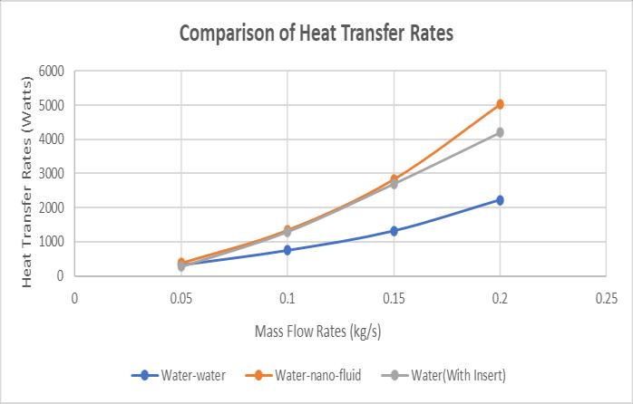
The heat transfer rates of concentric circular plane tubes without insert and with insert are compared in Figure 11. In the case of cold fluid, one arrangement has water flowingascoldfluid,andthenexttime,theSiO2nanofluid with a volume fraction of 0.4 is flowing as cold liquid, respectively. In both cases, water flows as a hot fluid. The correlationshowsthatthemostextremeworthofintensity move rate for a similar stream rate is accomplished for water-nanofluid game plan at 0.2kg/s with a worth of 5016.026 watts whereas the system having helical insert also showed great progress in comparison to simple heat exchanger.
Fig 13 shows the relative upsides of LMTD of concentric round plane cylinders with next to no supplements, with water-endlessly water nanofluid course of action individually.Thecomparisondemonstratesthatthewaternanofluid arrangement achieves the same LMTD value for the same flow rates, with a maximum of 9.21088 at 0.2 kg/s. The increase in the temperature difference between theinletandexitisthecauseofthisgrowth.becauseLMTD isdirectlycorrelatedwithtemperaturechangesattheinlet andexit.Asaresult,themassflowratealsoincreases.The helical insert with a pitch length of 2.5 inches and a value of12.19386KachievesthehighestpossibleLMTDvalue.
Fig11RateofHeatTransferversusmassflowrateofHot FluidinCounterFlowarrangement
Fig12OverallHeattransfercoefficientversusmassflow rateofColdFluidinCounterFlowarrangement
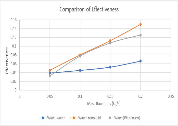
5.6 Comparison of Effectiveness based on Computational analysis of all the three cases
In the water-water and water-nanofluid systems, the effectiveness of concentric circular plane tubes without inserts and with a counterflow arrangement is compared in Figure 14, respectively. The comparison demonstrates that water with inserts achieves the highest value of effectivenessforthesameflowratesat0.2kg/s.
International Research Journal of Engineering and Technology (IRJET) e-ISSN:2395-0056
Volume: 09 Issue: 12 | Dec 2022 www.irjet.net p-ISSN:2395-0072
3) It should be mentioned that the LMTD for the waternanofluid arrangement was found to be 9.21 K, which is higherthantheLMTDforthewater-waterarrangementby 24% but lower than the LMTD for the water-water arrangement with a helical insert by 24%, which is 12.19 K.
4) The effectiveness of the water-nanofluid arrangement was also found to be maximum with a value of 0.149, which is higher than the effectiveness of the water The water-watercasewithhelicalinsertshasamaximumvalue of0.1255,whichis16%lowerthanthenanofluidcase.
5)Whencomparedtothewater-waterarrangement,which had a value of 2219.11 Watts for the same working conditions, the maximum heat transfer rate was noted to have increased by an astonishing 126% for a mass flow rate of 0.2 kg/s for the water-nanofluid arrangement. The same heat transfer rate is 54% higher than what helicalinserted tubes can achieve after consideration of Performanceevaluationcriterion.
References
[1] Chaiyanan Kamsuwan, Xiaolin Wang, Lee Poh Seng , Cheng Kai Xianc , Ratchanon Piemjaiswang, Pornpote Piumsomboona, Yotsakorn Pratumwal, Somboon Otarawanna, Benjapon Chalermsinsuwan (2022). Simulation of nanofluidmicro-channel heat exchanger using computational fluid dynamics integrated with artificialneuralnetwork,9thInternationalConference on Power and Energy Systems Engineering (CPESE 2022),DoshishaUniversity,Kyoto,Japan,(2022).
[2] Vedant Irabatti, Yash Patil, Sandeep Kore, Vaishnavi Barangule, Abhishek Kothe (2022). Comprehensive review of spiral heat exchanger for diverse applications.MaterialsToday:Proceedings(2022).
6. CONCLUSION:
1) In this investigation, the properties of the SiO2 nanofluid were discovered and characterized in programming for various fixation factor advantages. Nanofluid performance was found to be best at the concentration of 0.4, which was chosen for the heat exchanger'sperformancecalculation.
2) The current investigation reveals that the counter flow arrangement of a water-water heat exchanger has a maximumheattransfercoefficientof 7624.53 Watts/m2k, which is 42% lower than the value we obtained for a water-nanofluid arrangement, which is 13039.99 Watts/m2K, and is 36% higher than the heat exchanger withtwistedinserts.
[3] S. Raja, MS. Sivahari Shankar, P. Mathan Kumar , C. Rajaganapathy (2022). Heat transfer analysis and enhancement in shell and tube heat exchanger using copper oxide Nano particles; Materials Today: Proceedings(2022).
[4] Pavushetti Abhilash, Udutha Raghupati, Raghavan Nanda Kumar(2021).DesignandCFDanalysisofhair pin heat exchanger using aluminium and titanium carbide nanofluids; Materials Today: Proceedings (2021).
[5] N. Parthiban, M. Rajkumar, S.N. Murugesan (2021). Experimental study of comparison in performance of heat exchanger with and without silicon dioxide nano particle used in cold fluid. Materials Today: Proceedings(2021).
International Research Journal of Engineering and Technology (IRJET) e-ISSN:2395-0056
Volume: 09 Issue: 12 | Dec 2022 www.irjet.net p-ISSN:2395-0072
[6] Shu-Rong Yana, Hazim Moria , Samira Pourhedayat , Mehran Hashemian (2020). A critique of effectiveness concept for heat exchangers; theoretical-experimental study,InternationalJournalofHeatandMassTransfer (2020).
[7] J.I. Corcoles , J.D. Moya-Rico, A.E. Molina, J.A. Almendros-Ib anez (2020). Numerical and experimental study of the heat transfer process in a double pipe heat exchanger with inner corrugated tubes. International Journal of Thermal Science (2020).
[8] Miftah Altwieb, Krzysztof J. Kubiak, Aliyu M. Aliyu, Rakesh Mishra (2020). A new three-dimensional CFD model for efficiency optimisation of fluid-to-air multifin heat exchanger. Thermal Science and Engineering Progress(2020).
[9] A. Zargoushi, F. Talebi, S.H. Hosseini (2019). CFD modeling of industrial cold box with plate-fin heat exchanger: Focusing on phase change phenomenon. International Journal of Heat and Mass Transfer (2019).
[10] Chamil Abeykoon (2019). Compact heat exchangers –Design and optimization with CFD International JournalofHeatandMassTransfer146(2020)118766
[11] P.C. Mukesh Kumar, M. Chandrasekar (2019). CFD analysis on heat and flow characteristics of double helically coiled tube heat exchanger handling MWCNT/waternanofluids.Heliyon5(2019)e02030
[12] A.Natarajan,R.Venkatesh,S.Gobinath,L.Devakumar, K. Gopalakrishnan (2019) CFD simulation of heat transfer enhancement in circular tube with twisted tape insert by using nanofluids Materials Today: Proceedings(2019).