International Research Journal of Engineering and Technology (IRJET) e-ISSN:2395-0056

Volume: 09 Issue: 12 | Dec 2022 www.irjet.net p-ISSN:2395-0072
International Research Journal of Engineering and Technology (IRJET) e-ISSN:2395-0056
Volume: 09 Issue: 12 | Dec 2022 www.irjet.net p-ISSN:2395-0072
Rajkumar Bhagat1, Harsh Khandelwal2, Shreyash Khandwe3, Akshay Khubchandani4, Kanhaiya Kuche5, Sohan Kulal6, Utkarsha Chinde7
1Faculty, Vishwakarma Institute of Technology, Pune, Maharashtra, India 2-7 B. Tech, Mechanical Department, Vishwakarma Institute of Technology, Pune, Maharashtra, India ***
Abstract - Selection of power systems for underwater vehicles is an important task. The power system must be compact enough to fit inside the vehicle and it should supply sufficient power. This paper presents thermodynamic analysis of the Stirling engine based on schmidt analysis for underwater application. Alpha type engine with opposed cylinder configuration is selected. After the analysis, Dimensions for each component are selected followedbystructuralanalysis of engine components.
Key Words: Stirling Engine, thermodynamic analysis, underwater application, cooler, Regenerator, Unmanned vehicle.
Stirling Engine is a closed cycle heat engine in which no external air is required which makes it ideal for underwater application. The silent operation of it makes the vehicle more stealthy which makes the engine attractiveformilitaryapplications.Inthe2005wargames, USS RonaldReagan,anewlyconstructed$6.2billiondollar aircraft carrier, was sunk after being hit by multiple torpedoes. This torpedo was launched by Sweden’s submarine named “Gotland”. Gotland snuck past uss ronald reagan defenses. Americans never saw it coming and Yet despite making multiple attack runs on the Reagan, never saw it leave. Previously, diesel submarines couldonlynavigate with noisy diesel engines powered by airand stayunderwaterfor a few days. As a result, diesel submarines were most vulnerable while snorkeling and could be easily tracked. On the other hand, submarines fueled by nuclear reactors require large amounts of coolanttopreventameltdown.Hencepumpingofcoolant createsnoisesandvibrationswhichcanbeeasilydetected by SONAR. The Swedish Gotlands uses a 75 KW stirling enginewhichisanExternalcombustionengine.Therefore frequent combustion does not take place while operation and there is gradual compression and expansion of workinggaswhichmakesitmoresilent.
Stirling Engines can be used for the underwater vechicles that can operate underwater with or without a human
occupant. They can be used for surveillance and other missions that require very quiet operation. A closed-cycle heat engine has potentially better overall energy density than available battery systems. For example, 100 mile range, Submersible with 2m Diameter and 10m Length operating at 10 Knots for 1 hour requires 200 KW-Hr of energy. If we use a 35W-hr/Kg lead acid battery, We would require 6 tons of it. Above requirement can be fulfilledbythe15kW,100kgstirlingengine.Althoughthe weightofthe reactantstoragemust beaddedtothis,the total propulsion package with a Stirling could be lighter thanthepropulsionpackagewithadvanced batteries.
Among Alpha, Beta, Gamma type stirling engines, Alpha typeismoreefficientandhasmorepowerdensity.Sothat, Alpha type stirling engine with opposed cylinder configuration is designed. In this type of configuration, Insteadof displacer,Twoseparatecylindersareused.One is connected to the heater and the other is connected to thecooler.Regeneratorbetweenheaterandcooleractsas aheatreservoir.
Thepurposeofthisarticleisto designtheStirlingengine and its various components as well as the analysis of the engine (strain, stress, deformation). Theoretical thermodynamic analysis was also performed for the engine.
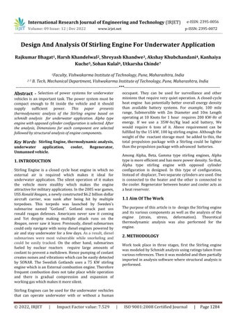
Work took place in three stages, first the Stirling engine wasmodeledbySchmidtanalysisusingratingstakenfrom variousreferences.Thenitwasmodeledandthenpartially importedinanalysissoftwarewherestructuralanalysisis performed.
International Research Journal of Engineering and Technology (IRJET)
e-ISSN:2395-0056
Volume: 09 Issue: 12 | Dec 2022 www.irjet.net p-ISSN:2395-0072
Fig -1:MindMap
Opposite cylinder configuration type is selected for the design for the optimum use of volume inside the vehicle. Schmidt's analysis is used to model the system. This analysis is still used today as the classical analysis of the Stirlingcycle.
Followingaretheassumptionsforthisanalysis:
● workingfluidobeysidealgaslaw
● Engineisperfectlysealedandthereisnoworking fluidleakage.Thustotalmassofworkingfluidisconstant
● Temperatureineachworkingspace (compression,Expansion) isknownandthereisno temperaturegradient
● Engineisrunningatconstantspeed
● Uniforminstantaneouspressureintheworking space
Followingaresomeoftheparametersselectedforthe engine:
Stroke=60mm
Crankradius(r)=30mm Clearancelength=4mm BoreDiameter(D)=52.4mm
Tc=350K
Th=923K n=1200rpm
Vregen=154cm3
Dregen=60mm
Lregen= 4Vregen/πD2 regen
Lregen=54.46mm
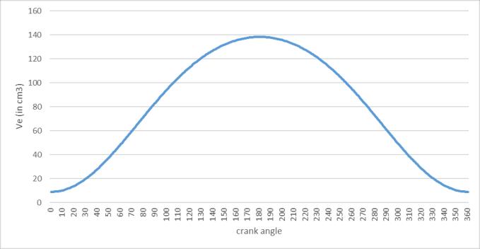
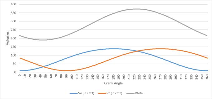
Now,Let’sfindoutvariationofworkingvolumeswith crankangles
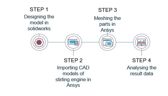
Obliquityratio
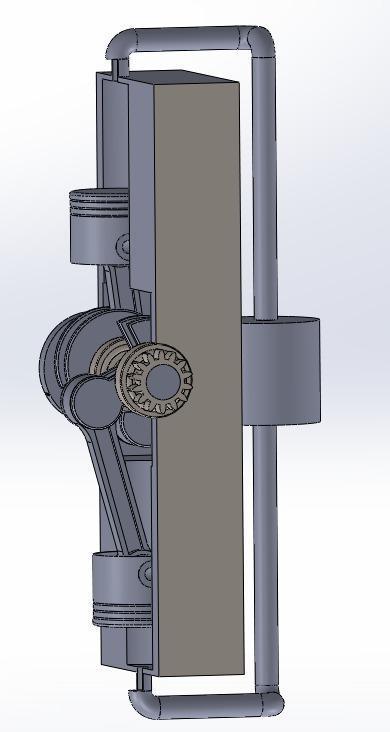
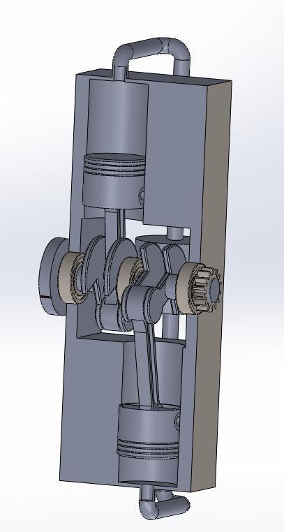
Fig -2:EnginesystemConfiguration
Xp = √ √ )
Ve √
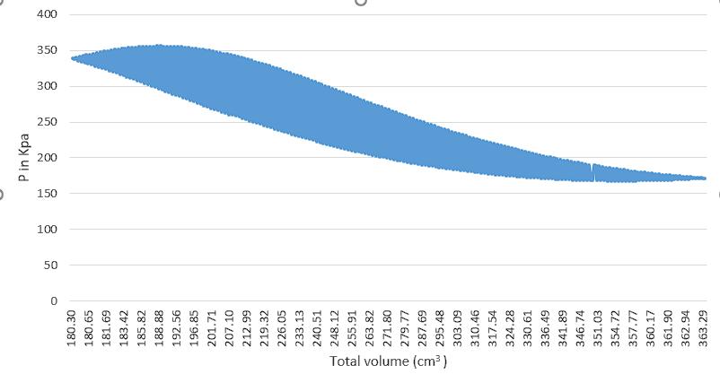
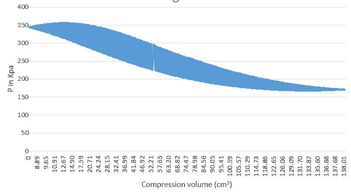
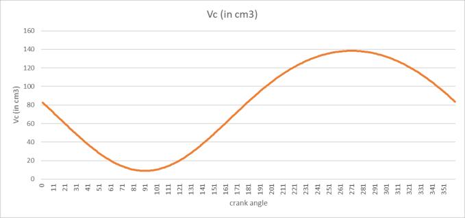
Similarly,wecanfindoutvariationofcompressionvolume withcrankangle
Vc √
Massofthegas
M=(Patm Vtotal(max)) (RTinitial)
Where, Patm=101325N/m2 Vtotal(max)=372.63cm3 Tinitial=293.15k R=287J/kg-k
M=0.4375g
Mtotal=Me+Mc +Mregen Mtotal =P/R(Ve/Te+Vr /Tr+Vc /Tc)
P=Mtotal R/(Ve/Te+Vr /Tr+Vc /Tc)
Tr =(Th -Tc)/ln(Th /Tc)
Tr=590.9K
Torquedevelopedbyexpansionpistononcrankwillbe givenby-
International Research Journal of Engineering and Technology (IRJET) e-ISSN:2395-0056
Volume: 09 Issue: 12 | Dec 2022 www.irjet.net p-ISSN:2395-0072
Te=rFp [sin +sin(2 )/2√[(n2-sin2 )] Where, Fp=π/4D2 P
Torquedevelopedbycompressionpistononcrankwillbe givenbyTc=rFp [cos +sin(2 )/2√(n2-cos2 )]
Totaltorque(T)=Te +Tc
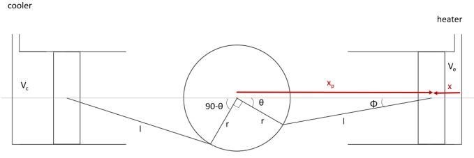
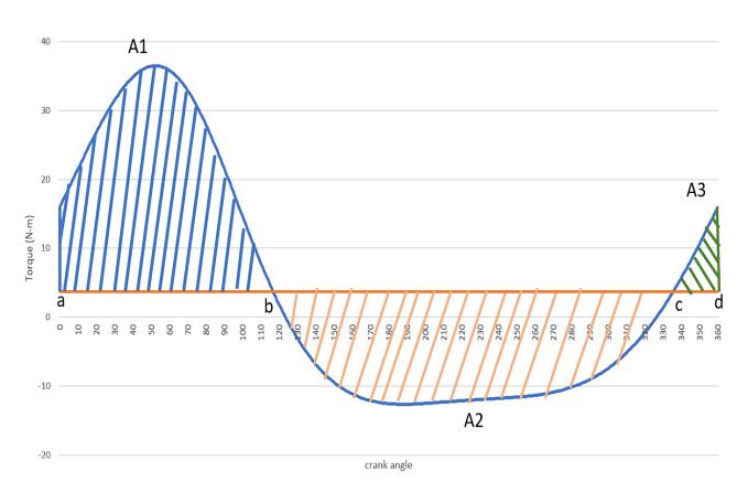
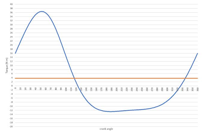
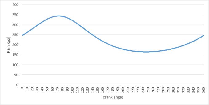
Chart -1:Turningmomentdiagram
Workdevelopedbytheengine=workrequireforan application
Areaofturningmomentdiagram=Tmean 2pi
Tmean =Areaofturningmomentdiagram/2pi Tmean =22.88/2pi=3.64Nm
LetenergyatpointabeE
A:E b:E+A1 c:E+A1-A2 d:E+A1-A2+A3=E
MaximumfluctuationofenergyΔE=maximumenergy-Minimumenergy ΔE=energyatb-energyatc ΔE=(E+A1)- (E+A1-A2) ΔE=A2=46.85Nm
Coefficientoffluctuationofspeed(Cs)=0.03 Soliddisktype flywheelisselected Maximumfluctuationofenergyinflywheel=½Iw2Cs ΔE=½Iw2 Cs
Where, W=2pin/60=125.66rad/s
I=0.098Kg-m2
I=M(Ro 2-Ri2)/2 M=ρ ㅠ (Ro 2-Ri2)t
I= ρ ㅠ (Ro 2-Ri2)2 t/2
ρ=7800kg/m3 (carbonsteel) Ri=shaftradius=10mm t=10mm
Ro=31.53mm
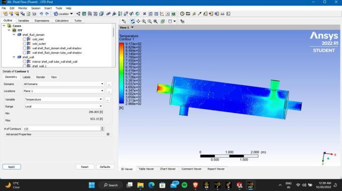
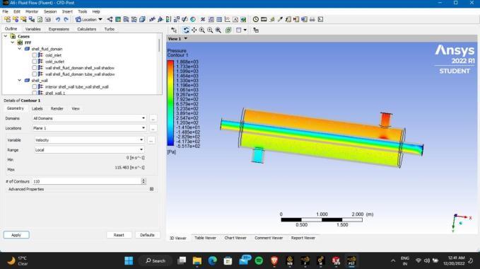
For cooler, Equivalent model was designed using ansys and the analysis is carried out. Taking the regenerator temperature as the inlet, We must achieve the temperatureof 350K.Thesurfaceareaiscalculatedwhich can produce that much temperature difference. Following parametersaretakenfortheanalysis:
Table -1: Specifications
Coolertemperature 20-300C,Average:250C
Chart -2:TurningMomentwithArea
A1=45Nm
A2=46.85Nm A3=2.5Nm
Heatertemperature 923K=6500C
Heatingmethod liquidoxygenanddiesel tocreatetheheatingof theengineinthe
International Research Journal of Engineering and Technology (IRJET) e-ISSN:2395-0056
Volume: 09 Issue: 12 | Dec 2022 www.irjet.net p-ISSN:2395-0072
combustionchamber.
Coolingmethod coldseawater material copper tubediameter 300mm shelldiameter 1000mm length 4000mm Itwasobservedthatsurfaceareaof0.2827m2 issufficient toproducethetemperaturedifference
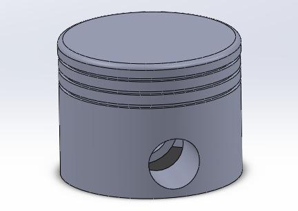
The pistons of the Stirling engine are hermetically sealed and are driven to move up and down as the gas inside expands.Weusegraycastironmaterialforpiston.
Thedesignoftheflywheelisdoneintheprevioussection. Itisusedtominimizethefluctuationsintheoutputpower. Carbonsteelisusedasamaterial
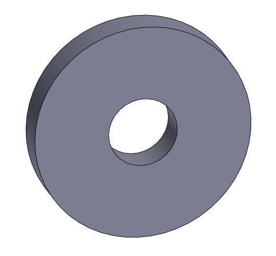
Fig -2:PistonCADModel
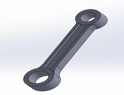
A device used to connect two moving parts, where it is usedbetweenthecrankshaftandthepiston.Herewehave usedcarbonsteelmaterialforit.
TheGudgeon/pistonpinisusedtoconnectthepistonto theconnectingrod.Italsoprovidesabearingonwhichthe connectingrodrotatesasthepistonmoves.
In a Stirling engine, the regenerative is an internal heat exchanger and a heat reservoir temporarily placed betweenthehotandcoldspacessothattheworkingfluid passes through it first in one direction and then in the other. Its function is to retain in the system heat that would otherwise be exchanged with the intermediate temperaturemediumatthemaximumandminimumcycle temperatures.Copperisusedasamaterial.
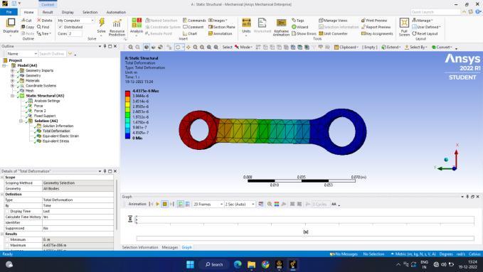
Fig -3:ConnectingRodCADModel
International Research Journal of Engineering and Technology (IRJET) e-ISSN:2395-0056
Volume: 09 Issue: 12 | Dec 2022 www.irjet.net p-ISSN:2395-0072
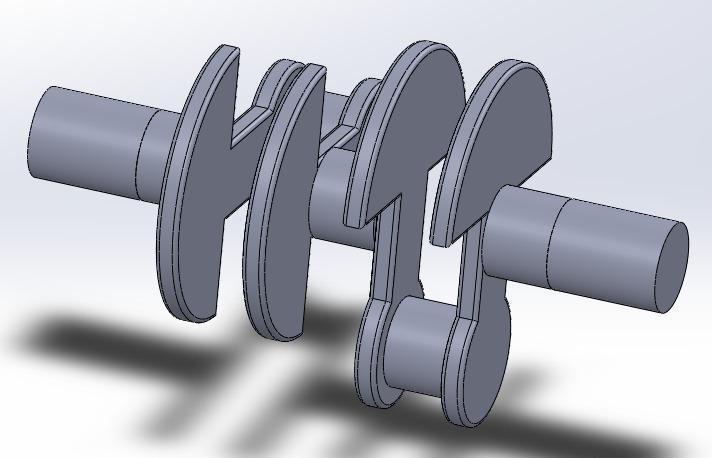
The shaft through which the mechanical work is transferredfromthepistontotheflywheel.
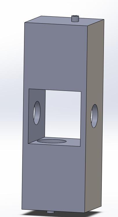
Anenginehouseisastructurethatholdsthemovingparts.
Abearingisapartofmachinerythatlimitsmotionrelative to only the desired motion and reduces friction between movingparts.
Fig -7:EnginehousingCAD

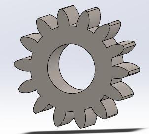
Spur/Cylindricalgearsareusedinmechanicalapplications toincreaseordecreasethespeedofequipmentormultiply torquebytransmittingmotionandpowerviaabeltdrive.
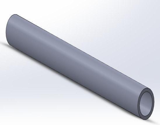
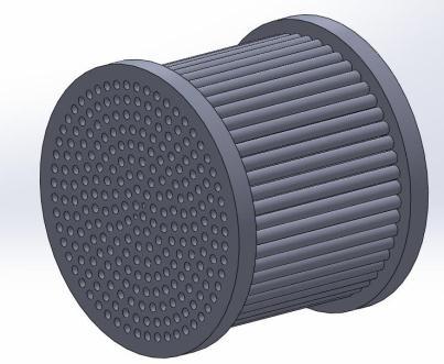
Fig -10:BearingCADModel
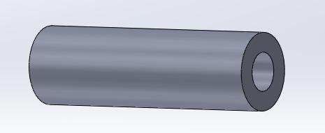
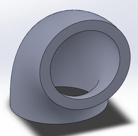
Fig -11:PipeCADModel
Fig -8:SpurgearCADModel
International Research Journal of Engineering and Technology (IRJET) e-ISSN:2395-0056
Volume: 09 Issue: 12 | Dec 2022 www.irjet.net p-ISSN:2395-0072
International Research Journal of Engineering and Technology (IRJET) e-ISSN:2395-0056
Volume: 09 Issue: 12 | Dec 2022 www.irjet.net p-ISSN:2395-0072
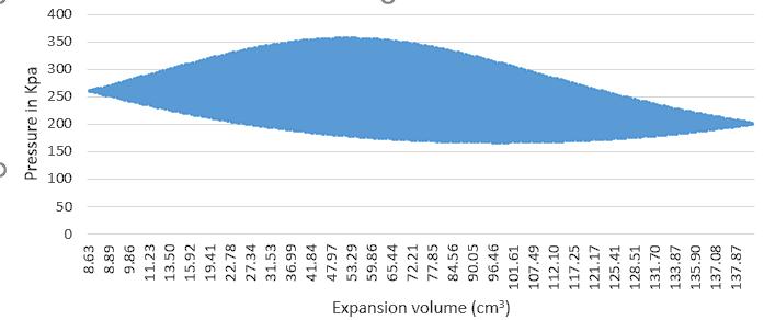
Chart -8:VariationofPressurewithExpansionVolume
International Research Journal of Engineering and Technology (IRJET) e-ISSN:2395-0056 Volume:
International Research Journal of Engineering and Technology (IRJET) e-ISSN:2395-0056
Volume: 09 Issue: 12 | Dec 2022 www.irjet.net p-ISSN:2395-0072
[2] Hargreaves, Clifford M. "The Phillips stirling engine."(1991).
[3] Martini, WilliamR.Stirling enginedesignmanual. No.NASA-CR-168088.1983.
[4] Organ, Allan J. "The regenerator and the Stirling engine."(1997).
[5] Walker,Graham."Stirlingengines."(1980).
[6] Sripakagorn, A. and Srikam, C., 2011. Design and performance of a moderate temperature difference Stirlingengine.RenewableEnergy,36(6),pp.1728-1733.
[7] Urieli, Israel, and David M. Berchowitz. "Stirling cycleengineanalysis."(1984).
[8] Ahmadi, Mohammad H., Mohammad-Ali Ahmadi, and Fathollah Pourfayaz. "Thermal models for analysis of performanceofStirlingengine:Areview." Renewableand SustainableEnergyReviews68(2017):168-184.
[9] Costea,M.,S.Petrescu,andC.Harman."Theeffect of irreversibilities on solar Stirling engine cycle performance."Energyconversionandmanagement40,no. 15-16(1999):1723-1731.
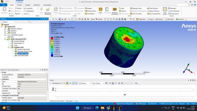
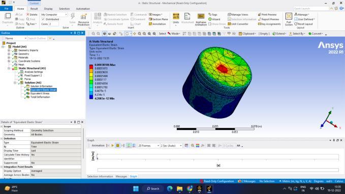
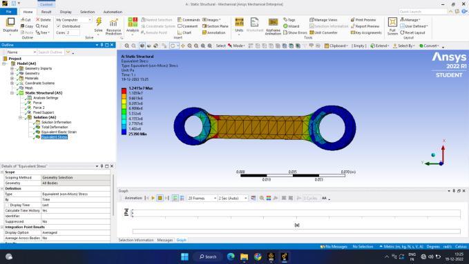
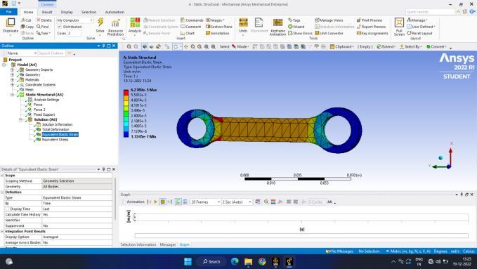
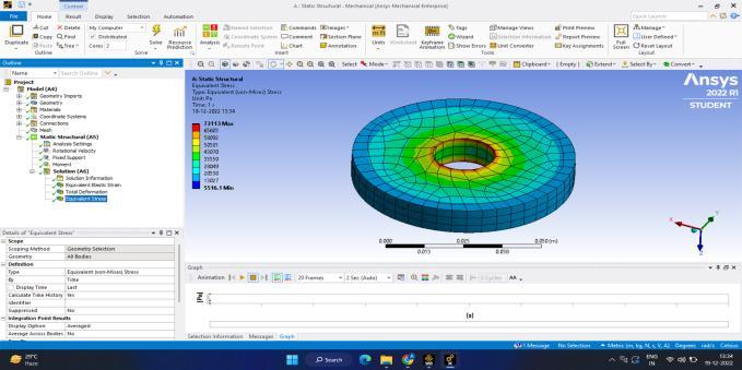
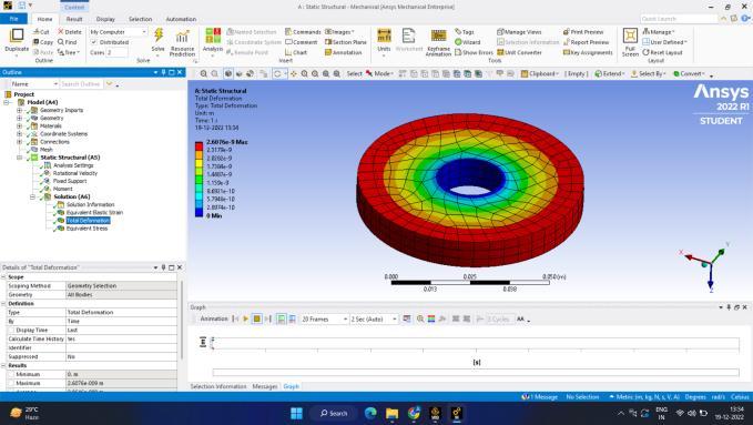
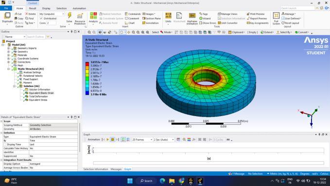
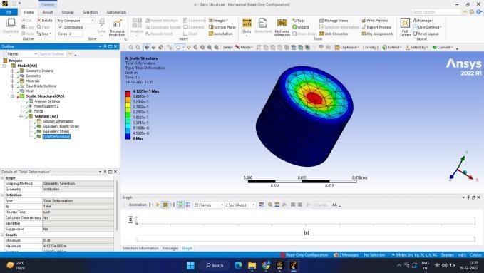
Bydoingthethermodynamicanalysis,Itisconcludedthat workdoneforcompressionis smallerthanworkobtained intheexpansionstroke.Sothatnetworkof10.735Jouleis obtained.considering1200rpmspeed,cyclecompletedin 1second will be20hencepowerobtainedis214.7Watts. Structural analysis is done in ansys and the deformation, Vonmisesstress,strainiscalculated.Stressinducedinthe piston was 41 Mpa and 21 Mpa for the connecting rod whicharewellwithinthepermissiblelimits.
Effect of pressure drop due to friction can be taken into considerationtocorrectlymodelthermodynamicanalysis Working fluid like helium can be used for the efficient operation due to its high conduction coefficient and low dragcoefficient.
[1] Reader, Graham Thomas. "Stirling engines." (1983).
[10] Chen, N. C. J., and F. P. Griffin. Review of Stirlingengine mathematical models. No. ORNL/CON-135. Oak RidgeNationalLab.,TN(USA),1983.
[11] Singh,UdayRaj,andAnilKumar."Reviewonsolar Stirling engine: Development and performance." Thermal ScienceandEngineeringProgress8(2018):244-256.
[12] Campos, M. C., J. V. C. Vargas, and J. C. Ordonez. "Thermodynamic optimization of a Stirling engine." Energy44,no.1(2012):902-910.
[13] Paul, Christopher J., and Abraham Engeda. "Modeling a complete Stirling engine." Energy 80 (2015): 85-97.
[14] Scollo, L. S., P. E. Valdez, S. R. Santamarina, M. R. Chini,andJ.H.Baron."Twincylinderalphastirlingengine combined model and prototype redesign." International journalofhydrogenenergy38,no.4(2013):1988-1996.
[15] Almajiri, Ahmad K., Saad Mahmoud, and Raya AlDadah. "Modeling and parametric study of an efficient Alpha type Stirling engine performance based on 3D CFD analysis." Energy conversion and management 145 (2017):93-106.
International Research Journal of Engineering and Technology (IRJET) e-ISSN:2395-0056
Volume: 09 Issue: 12 | Dec 2022 www.irjet.net p-ISSN:2395-0072
[16] Altin,Murat,MelihOkur,DuyguIpci,SerdarHalis, and Halit Karabulut. "Thermodynamic and dynamic analysisofan alpha typeStirling engine with Scotch Yoke mechanism."Energy148(2018):855-865.
[17] Tlili, I. A. "Numerical investigation of an Alpha StirlingengineusingtheRossYokelinkage."HeatTechnol 30(2012):23-36.
[18] Boretti, Alberto. "α-Stirling hydrogen engines for concentrated solar power." International Journal of HydrogenEnergy46,no.29(2021):16241-16247.
[19] Zare, Shahryar, and AliReza Tavakolpour‐Saleh. "Free piston Stirling engines: A review." International JournalofEnergyResearch44,no.7(2020):5039-5070.
[20] Alberti, Fabrizio, and Luigi Crema. "Design of a new medium-temperature Stirling engine for distributed cogeneration applications." Energy Procedia 57 (2014): 321-330.
[21] Brett,C."The4-95Stirling engineforunderwater application." In Proceedings of the 25th Intersociety Energy Conversion Engineering Conference, vol. 5, pp. 530-533.IEEE,1990.
[22] Reader, Graham T., Ian J. Potter, Eric J. Clavelle, and Owen R. Fauvel. "Low power Stirling engine for underwater vehicle applications." In Proceedings of 1998 International Symposium on Underwater Technology, pp. 411-416.IEEE,1998.
[23] Potter, Ian J., and Graham T. Reader. Operational feasibility of underwater Stirling engine systems using oxygen-seawaterextraction.No.CONF-950729-.American Society of Mechanical Engineers, New York, NY (United States),1995.
[24] Reader, G. T., and I. J. Potter. "Stirling machine technology for subsea intervention." In The Ninth International Offshore and Polar Engineering Conference. OnePetro,1999.
[25] Aoki,Taro, SatoshiTsukioka,TakashiMurashima, HiroshiYoshida,HidehikoNakajoh,TadahiroHyakudome, Shoujirou Ishibashi, and Ryoko Sasamoto. "Deep Sea Unmanned Underwater Vehicles in JAMSTEC." In The Thirteenth International Offshore and Polar Engineering Conference.OnePetro,2003.
[26] Oelrich, Ivan C., and Frederick R. Riddell. Evaluation of Potential Military Applications of Stirling Engines. INSTITUTE FOR DEFENSE ANALYSES ALEXANDRIAVA,1988.
[27] FIJALKOWSKI, BOGDAN THADDEUS. "Unmanned Submarines (US) for Noiseless Naval Hazardous-Duty Missions."
[28] Li, Daijin, Kan Qin, and Kai Luo. "Underwater stirling engine design with modified one-dimensional model." International Journal of Naval Architecture and OceanEngineering7,no.3(2015):526-539.
[29] Friedman, Norman. "Submarines-the future." Asia-PacificDefenceReporter(2002)36,no.10(2010).
[30] Reader, G. T., J. Potter, and J. G. Hawley. "The evolution of AUV power systems." In OCEANS 02 MTS/IEEE,vol.1,pp.191-198.IEEE,2002.
[31] Bratt, Christer, and Hans-Goran Nelving. "Development and production of Stirling engines for submarineandsolarapplicationatKockums."(2000).