International Research Journal of Engineering and Technology (IRJET) e-ISSN:2395-0056

Volume:09Issue:12|Dec2022 www.irjet.net p-ISSN:2395-0072
THERMAL MANAGEMENT IN EV
Sayed Umar Masood1, Mohd Qasim Farooqui 2, Zishan Shahzad3, Moazzam Farooque4
1Sayed Umar Masood, Dept. of Mechanical Engineering, Jamia Millia Islamia, New Delhi, India
2Mohd Qasim Farooqui, Dept. of Mechanical Engineering, Jamia Millia Islamia, New Delhi, India
3Zishan Shahzad, Dept. of Mechanical Engineering, Jamia Millia Islamia, New Delhi, India
4Moazzam Farooque, Dept. of Mechanical Engineering, Jamia Millia Islamia, New Delhi, India ***
Abstract - Optimum performance and efficiency of battery packs can be obtained in certain Temperature Range; to achieve this we must have a fail-proof thermal management system.
Extensive Simulations were conducted on the battery model with different cooling systems like Air cooling, Liquid Cooling, Thermoelectric Cooling (TEC) and thorough results were taken down. All three cooling systems have been extensively studied and it is found out that they can lower the temperature of battery significantly, but Thermoelectric Cooling shows potential drop in battery temperatures to desired range, ultimately making the battery Thermally safe, Stable and efficient.
Also, Simulation results were analyzed for further improvement in the thermal efficiency of the battery pack.
1. INTRODUCTION
Advancesinelectricvehiclebatterieshaveallowedthem todelivermorepowerandrequirelesscharge,butoneofthe biggestchallengestobatterysafetyisdesigninganeffective cooling system. Electricvehicles generate heat when the batteries are discharged. The fasterthe batterydischarges,themoreheatitgenerates.Thebattery workson the principle of voltagedifference,hightemperature excitesthe electronsinside,reducingthevoltagedifferencebetweenthe two sides of the battery.Batteriesaredesigned to operateonlywithincertainextremetemperaturerangesand will ceasetofunctionifacooling systemis not in placeto keepthemwithinthatoperatingrange.Thecoolingsystem mustbeabletomaintainthebatterypackinthetemperature rangeofapproximately20-40°Candkeepthetemperature difference within the battery pack to a minimum(5°C or less).
Here are theparameters that affectbattery performance with increasing temperature: BatterylifeIftheinternaltemperaturedifferenceislarge,the charginganddischargingrateofeachcellwillbedifferent, which may reducethe performance of the batterypack. Potentialthermalstabilityissuessuchas:Overheatingofthe battery oruneventemperature distribution in the batterypackcanleadtoreducedcapacity,thermalrunaway,
fireexplosion,etc..Facedwithlife-threateningsafetyissues, the electric vehicle industryneeds innovationto improve batterycoolingsystems.
2. COOLING SYSTEM IN ELECTRIC VEHICLES
Thebasictypesofcoolingsysteminelectricvehiclearelisted below:
1. Lithium-IonBatteryCooling
2. PhaseChangingMaterialCooling 3. AirCooling 4. LiquidCooling 5. Thermo-ElectricCooling
2.1Lithium-ionbattery
Lithiumisaverysimplemetalandfallsunderthealkaline group of the periodic table. It has three electrons and an electronicconfigurationof1s2,2s1.Lithiumhasaveryhigh tendencyforelectronloss,andthisareamakeslithiumvery unstable.Althoughlithiummetaloxidesareastableformof lithium. Individual lithium-ion cells can reach very high voltageduetotheveryhighefficiencyofmetal.Alithium-ion batteryconsistsofseveralmodulesconnectedtoaseriesand each module contains individual cells connected in series andcompatible.Lithium-ionbatteryconsistsofthreemain components: 1. Lithium Metal oxide, 2. Electrolyte, 3. Graphite. Electrolyte separates lithium metal oxide from graphite. Lithium-ion batteries operate in two stages: Charging and discharging. During the charging stage, it connects the cell to the power source. It connects lithium Metal Oxide to a direct terminal (anode) and connects graphitewithanegativeterminal(cathode).Theelectronin thelithiumvalenceshellisattractedtoafineenergysource terminal. Electrolyte acts as a guard and does not allow electronstopass.Electronspassthroughtheoutersupply andreachthegraphitelayer,andinthemeantime,lithiumion(Li+)passesthroughtheelectrolyteandistrappedinthe space between the graphite. When all the lithium-ion is trappedinsideasolidgraphitesheet,thecellisfullycharged.
Lithium-ionandElectronbuilt-inchargingisaveryunstable platformso whena powersourceis replacedtheloadthe batterystartstoleak out.Lithium-ion travelsto the metal
International Research Journal of Engineering and Technology (IRJET) e-ISSN:2395-0056
Volume:09Issue:12|Dec2022 www.irjet.net p-ISSN:2395-0072
oxidebyelectrolytetocreateastablestateoflithiummetal oxide.Electronsbegintomovetotheanodewithaloadand thuswegetelectricalenergyperload.Whenalltheelectrons and lithium-ions return to normal, they discharge the battery.Graphiteusedinacellactsasalithium-ionstorage anddoesnotcontributetochemicalreactions.Thisprocess and electricity also generate heat. Lithium-ion batteries produceheatduetocomplexinternalmechanismssuchas: 1)exothermicchemicalreactions2)ohmicresistance3)cell separation due to battery power differences between chargingandchargingopencircuit4.Lithium-ionbatteries getahotescapeundercertainconditions.ThermalRunaway is a process in which sensitive temperatures inside the batteries begin to deteriorate dramatically and produce excessive heat. If the heat cannot escape as soon as it is producedthisevaporativereactioncannotbestopped.Here, ifthepropercoolingmethodisnotusedtoeliminatetheheat generated by the cell it explodes. Cell rupture causes side effects. So choosing the right cooling module for such a batterymoduleisimportant.Inthispaper,wefocusonthe coolingmethodsused.
2.2PhaseChangeMaterialCooling
A phase changer is something that releases or absorbs enoughenergyinaphasechangetoprovideausefulthermal orcoolingeffect.PCMhassuchasystembecauseofitshigh ambienttemperature.ThemostwidelyusedPCMsareRT35, RT15 (Ruby Therma 15), EG5 (expanded graphite 5), and EG26.TheoperatingtemperatureofPCMrangesfrom-40°C to 150 ° C. PCM is the main solution for the efficient operationofanelectricvehiclebymaintainingacontinuous distribution of heat even in any temperature conditions. Divisions: Category Changes are divided into three main categories:
Organic (paraffin compounds, non-paraffin compounds), Inorganic(Salthydratesmetallics),andEutecticcompounds. Alternative organic substances and salt hydrates are preferablewhenoperating attemperaturesbelow100°C (eg Li-Ion batteries). Eutectic compounds can be used at temperatures up to 250 ° C. Organisms have an ambient mixingtemperatureataspectrumof128to200KJ/Kgwhile Inorganic compounds with a range of 250-400KJ / Kg. Organics PCM is usually divided into two sub-categories: paraffin and non-paraffin. Paraffin is tested to be safe, chemicallystable,reliable,andinexpensive.Inaddition,they havealowvolumetricelasticitythroughphaseconversion and have a low conversion rate. Paraffin is made up of alkanes chains whose chemical composition and formulas are CH3 (CH2) mCH3 and CnH2n + 2. Typically, paraffin phase transformers have a melting temperature and the ambient temperature increases logarithmically with an increaseinthenumberofcarbonatoms.Non-paraffincanbe classifiedasesters,alcohol,glycols,andfattyacids.Normally organicPCMsarenotparaffinseparatedbyhighcomposite temperatures, non-combustion, low thermal conductivity,
wild toxicity, and instability at high temperatures. In addition, fatty acids are a very important subgroup of unhealthy PCMs. They have a higher combustion temperaturecomparedtoparaffinandhavenoproblemwith thermalhysteresisandsubcoolingduringfreezingprocesses. ThechemicalstructureandformulaareCH3(CH2)mCOOH andCnH2nO2.Thethermalconductivityoffattyacidsisvery low, i.e. from 0.14K / mK to 0.17K / mK. The thermal diffusivitiesoffattyacidsrangefrom7.5m2/sto10-2m2/ s.Theadvantagesofnon-paraffinPCMsaregoodchemical stability, non-toxicity, low volume expansion, compliance with storage properties, high ambient temperature and power fullness, no effect of low cooling and phase separation. Disadvantages of non-paraffin PCMs are more expensivecomparedtoparaffinandsaltyhydrates.Thecost ofnon-paraffinPCMisabout2to2.5timesthatofparaffin and more than that compared to saline hydrates. Organic non-InorganicPCMsaredividedintotwoparts:salthydrates and metalics. Salt hydrates are a mixture of inorganic salt alloys(AB)andwater(nH2O),formingacompoundwitha chemicalformulasimilartoAB(nH2O).InthistypeofPCM, melting / stabilizing water dissipation / salt flow. This causes the problem of salt hydrates i.e. processes of nonmixing or sedimentation during melting. This is because dehydratedsaltisheavierthanwaterandoftendecomposes atthebottomofthecontainer.Whenhydrationneedstobe activated,thesystemisdividedintoareasofdifferentsalt concentrations, so complete hydration installation is not possible.However,solutionstothisproblemhavealready beenfound,forexample,mechanicalstimulation,installation of PCMs to avoid the separation of depleted salts in their water, and the addition of special thickening materials. Anotherproblemwithsalthydratesistheirhighcooling,due to their low nucleation properties. It means that the nucleationrateofsalthydratesisverylowinthetransition temperatureandthematerialneedstobecooledveryhard beforethenucleationcanactnaturallyonsalthydrates.It meansreleasingheatenergystoredinthematerialatavery lowtemperatureandthusreducingtheenergyefficiencyof the heat storage system. There is little evidence that the additionofa nucleationagentoreveninjectingnucleican activate the cooling process. Overall, the advantages of highlysubtlesalthydrates, hightemperature fluctuations, low volatility during melting, low toxicity and decay (associatedwithplastics),andarecheapwhenusedinthe purest form. The last category of non-living PCMs is metallics. Metallic is a molten metal that melts at low temperatures.Theyhavealargevolumetriccapacitybutdue tohighdensity;theyhavealowenergydensity.PCMshave highthermalconductivity,andthereforedonotrequirethe development of thermal conductivity. Another category is eutectic compounds. Eutectic compounds for 2 or more PCMs, which at some point, melt at room temperature. Functionality: Phase Changing Material is a material that absorbs and releases heat energy during melting and cooling.WhenaPCMfreezes,itemitsalotofenergyinthe form of subtle heat at the same temperature. Conversely,
International Research Journal of Engineering and Technology (IRJET) e-ISSN:2395-0056
Volume:09Issue:12|Dec2022 www.irjet.net p-ISSN:2395-0072
when such substances melt they absorb large amounts of heat from the surrounding environment. PCMs are also chargedastheambienttemperaturefluctuates,makingthem suitableforavarietyofdailyusesthatrequiretemperature control. PCMs are designed to cover a wide range of temperaturesfrom-40°Ctoover150°C.Theyusuallystore 5to14timesmoreheatperunitvolumethanmaterialssuch as Water or Stone. Amid many heat storage alternatives, PCMsareattractivebecausetheyofferhigh-densityenergy storageandstoreheatwithinanarrowtemperaturerange.
2.3AirCooling
Air cooling generally uses the principle of convection for transferringheatawayfromthebatterypack.Asandwhen theairrunsoverthesurfaceofthebattery,itcarrieswithit theemittedheatbythesurface.Thistechniqueofcoolingis simplebutatthesametimenotveryyielding.Convectionisa processinwhichbulkmovementofmoleculeswithingases takes place. At the beginning stage heat transfer between objectandgastakesplacethroughconduction,butthebulk heat transfer takes place due to the movement of the gas. Whenthebatterygetsheatedthermalexpansiontakesplace. The lower layer which is hotter becomes less dense. We knowthatcolderpartisdenser.Duetobuoyancy,theless dense,hotterpartrisesupandthecolderdensereplacesit. Thisprocessisrepeatedandhencetheconvectionprocessis carried and the heat transfer is carried out. Convection is carriedoutbytwotypes.
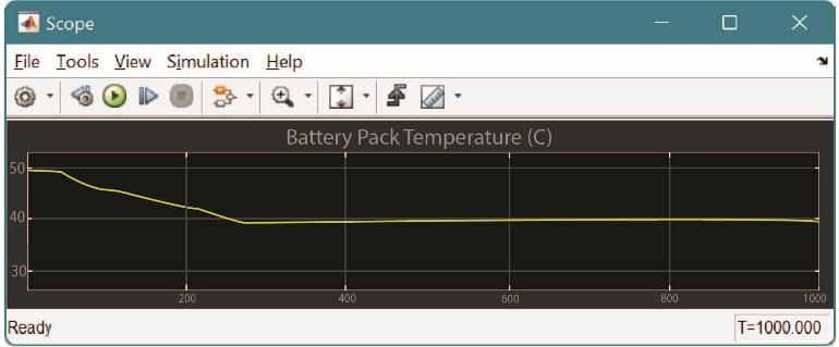
NaturalConvection
Forcedconvection.
Fig.1 Types of Convection
1.Naturalconvection:Whentheconvectiontakesplacedue tothebuoyantforcebecauseofthedifferenceindensities causedbythedifferenceintemperatureiscalledasnatural convection.Exampleofthismaybenaturalair.
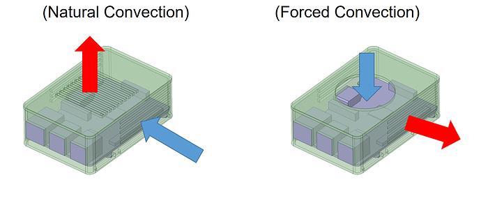
2. Forced convection: With presence of external sources being used for creating convection is called as forced convection.Thesesourcesmaybeexternallyaccommodated fans or pumps. These similar types of process are also involved in the thermal management of electric vehicles wherethevehiclesmaybecooledwiththehelpofnaturalair orwiththehelpoffan.
Fig.2 Thermal Management of Battery pack using Air Flow
Advantages:Aircoolingsystemislesscomplexandhaslow applicationcost.
Disadvantages:Aircoolingprocesscannotbeusedformost newhigh-performanceapplicationsduetothepowerdensity required and the wide range of ambient temperatures it needstomoderate.Itisnotpossibletoextractsufficientheat from the battery with the help of just the cooling system. Somecoolingmaytakeplaceinsidethebatterypackbutthat aloneisnotsufficienttobringdownexternaltemperatures toamoderatelevel.Thefanforforcedairextractionisbig anditneedspowerfromthebatterytobedrivenwhichmay resultinlargepressuredrop.
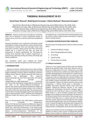
Fig.3 Temperature drop in Air Cooling System 2.4LiquidCooling
Liquidcoolinghasahightemperatureandheatcapacitysoit worksveryeffectively.Ithasitsadvantagessuchaseaseof planning and compact structure. Liquid cooling helps to maintainthecorrectbatterypacktemperature.Accordingto experienced researchers,liquidcooling isprobablyone of themosteffectivecoolingmethodscomparedtoanyother.A cold and warm microchannel model for a single type of liquidionbatterywasdevelopedbyZhao.Tongdesignedthe BTMS based cooling fluid (battery temperature control system)for the bipolarLithium-Ionbatterypack.Medium temperatureandtemperaturesimilaritycanbeimprovedby increasing the cooling flow rate or plate thickness. The coolingperformanceofanyliquidwilldependonitsthermal conductivityanditsviscosity.Themainconsiderationofany cooling liquid is a certain temperature. Plain water has a very high special temperature although it cannot be used
International Research Journal of Engineering and Technology (IRJET) e-ISSN:2395-0056
Volume:09Issue:12|Dec2022 www.irjet.net p-ISSN:2395-0072
alonesoitismixedwithglycol.Glycolisasubstanceofthe alcoholfamily.Itisalsousedwithwatertoprotectitfromad heat. Glycol blends with water are inexpensive and are a verystablecoolingfluid.Themixturecontains50%glycol, 45%waterand5%additives,whichmayincludeantifreeze, corrosioninhibitor,dyeandantioxidant.Glycolhasagood specificheatcapacityandhasgoodheattransferproperties. Water-glycolsystemsareconsideredindirectcooling.Glycol pumpingisdonethroughpipelinesaroundthebattery.The supplyofthiswater-glycolmixtureisprovidedusingsupply pumps.BTMSusesliquidcooling,heattransferisachieved byinsertingastraighttubearoundthebatterycellswitha jacket around the battery cells placing the hot liquid or cooling plate in place of the battery cell or immersing the cellsindielectricliquid.
Glycolusedcanbeoftwotypes:
1. Ethylene Glycol (EG): - This is used as an antifreeze for coolingcarengines.
2.PropyleneGlycol(PG):-PGhasthesamebenefitsasEG.In additionPGisconsideredtobenon-toxicaswell.
Batterycoolingcanbedividedintotwotypes
1.PassiveCooling
2.Activecoolingbasedoncontrolstrategies.
Inrandomcoolingthecooleriscooledwiththehelpofair through a uniform flow heat exchanger while in effective coolingthecooleriscooledwiththehelpofa refrigerator with an indoor heat exchanger. In idle cooling the cooling heatsinkisaradiator.Incoolingofaconstantfluidtheheat transferfluidistransmittedthroughpumpsinsideaclosed system. The circulating fluid will absorb heat from the batterypackandexpelitthrougharadiator.
In effective cooling there are two traps. The lower loop is calledthesecondloopandtheupperloopiscalledthemain loop.Themainloopissimilartoaloopinacoolingsystem, in which the heat transfer fluid is transmitted through a pump. The second loop in active cooling is an air conditioningloop.Inthiscasethehightemperatureswitch instead of the radiator acts as an evaporation cooler and connectsbothloops.Whentheheatingfunctionoccurs,the 4-way valve will be replaced and the high temperature switch will start operating as a condenser and the low temperatureswitchwilloperateasasteamer.
There are usually two types of fluids used in system temperaturecontrol.Firstisadielectricliquidalsocalleda directcontactliquidthatcandirectlycontactbatterycells, thisincludesmineral oil.Secondisa continuousfluidalso called indirect fluid that directly affects battery cells, this includesamixtureofethyleneglycolandwater.Adifferent structureisformeddependingonthetypeofliquid.Indirect contactliquid,thestructureisusuallyimmersedinmineral
oilwhileindirectcontactwithapotentialstructurecanbea jacket around the battery module, separate tubes around each module, placing the battery module on the cooling / heating plate or assembling the battery. cooling / heating modules and plates. Indirect communication systems are oftenpreferredtofindbetterseparationbetweenthebattery anditssurroundings.
Fig.4 Thermal Management of Battery using Liquid Cooling Advantages:Glycolcoolingrequireslessenergycomparedto aircoolingtomaintainthesamemoderatetemperature.It canwithstandrustandoperateoverlongdistances.Greater cohesion and greater uniformity of temperature between cells. It has a higher cooling rate compared to the air conditioningsystem.
Disadvantage:Glycollosesenergyovertime.Notcompatible with current composite chemistry. It also has potential concernsaboutpoweroutages,accordingtoastudybyAfton Chemical.Anyleakageinthiswaycanbeamajorproblem forthecar.Liquidcoolingisconsideredtobemorecomplex thanaircooling.Thisrequiresalotofspaceandtheweight of the car. The cost of this is high compared to the air conditioningsystem.
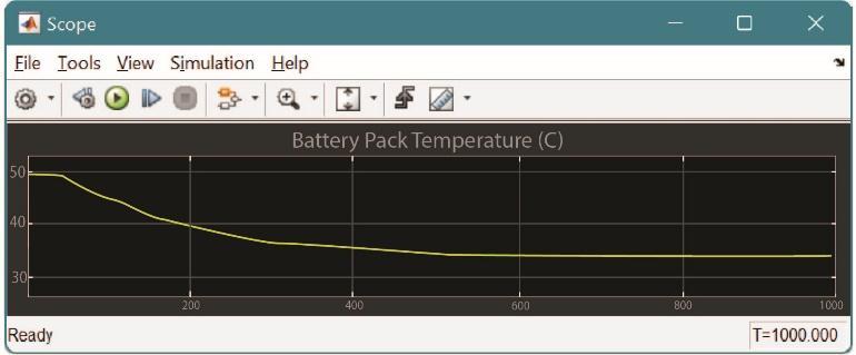
Fig.5 Temperature drop in Liquid Cooling System
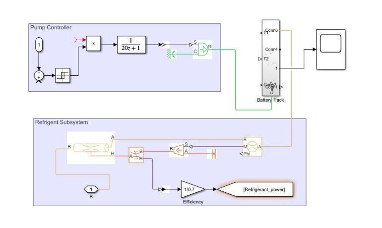
2.5Thermo-ElectricCooling
Thermoelectriccoolersusedinbatterytemperaturecontrol systems are relatively new technologies in the field of electric vehicles. Their advantages are strong cooling capacity and reliable performance and have gained the combined attention to the battery temperature control system.Amajorproblemwithairandwatercoolingisthat
International Research Journal of Engineering and Technology (IRJET) e-ISSN:2395-0056
Volume:09Issue:12|Dec2022 www.irjet.net p-ISSN:2395-0072
the cooling effect can be very limited under certain conditions. A thermoelectric module is a solid state converter that contains a large number of thermocouples connectedinseriesandinthermalcoupling.
Functional: Thermoelectric cooler (TEC) is based on convertingelectricalenergyintotemperaturedifferences.It refers to all the processes of conversion from heat to electricityandviceversa.ItworksaccordingtothePeltier effect. The result creates a temperature difference by carryingheatbetweenthetwoelectricaloutlets.Avoltageis applied to the entire conductor combined to generate electrical energy. When the current flows into two conductors,theheatisremovedfromoneofthepeninsula andthencools.Heatisappliedto thejunctionof thearea. ThekeytothePeltiereffectiscooling.Peltiereffectcanbe usedtoheatorcontroltemperature.
Thermoelectricelectriccoolinghasfeweradvantagesthan othercoolingsystemssuchasstationarydevice,nointernal chemical reactions, no noise, long operation, no harmful emissions,andthecostofrepairingit.Thedisadvantagesof TECarepoorefficiencyandtheneedforadditionalpower thatlimitstheircommercialuse.
SimulationModelSetup
We are using a Compression method for the TEC setup. Batterypackissandwichedbetweencoldplateandheatsink andpackedwithaluminumsheetsforheatconduction.Itis the most common & efficient way for TEC type cooling systems.
BatterySpecifications
Lithium Nickel Manganese Cobalt Oxide (NMC) cells were usedinourexperimentalElectricVehicle.Thereareatotalof 96cells.ThespecificationofNMCcellsareasfollows
Weight(g) 1580
NominalCapacity(Ah) 75
NominalVoltage(V) 4.2
OperatingTemperature(oC) -15to60
Sothe weightofthe battery pack isaround151 kgwith a total voltage of 403.2 V as cells were in series with each other.Totalcapacityofthebatterypackis75Ah.
Battery’s internal resistance
Ontheotherhand,thebattery’sactualterminalvoltageEemf deviates from equilibrium electromotive force (electrode potential)duetoelectrochemicalpolarizationofthebattery. This process generates heat Qp, which is the energy loss during polarization in the charge and discharge of the
battery.Qp=I2R,whereRpisthepolarizationresistancethat comes with polarization process. Finally, Joule heat Qi is generated because of the internal ohmic resistance of the battery. The heat generated during the charge/discharge processisQj=I2Ri,whereRiistheinternalohmicresistance oftheLi-ioncell.
LoadSpecifications
For our experimental electric vehicle we have Emrax 188 axialfluxmotorwiththefollowingspecifications:
Topspeed(km/h) 141 PeakTorque(Nm/sec) 50
MotorType AxialFluxMotor Phase ThreephaseAC NominalMotorVoltage(V) 150
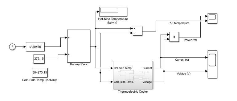
Fig.6 Thermal Management of Battery using ThermoElectric Cooling
Heat balance
Equation(1)expressesthetotalamountofheatperunittime duringthechargeQtc,whereIc isthechargingcurrent,and (2) expresses the total amount of heat Qtd per unit time duringdischarge,whereId isthedischargingcurrent.Rp is the polarization resistance that comes with polarization process & Ri is the internal ohmic resistance of the Li-ion cells.
Qtc=-nFT( )+(Rp +Ri)Ic 2 …………………..(1)
Qtd= nFT( )+(Rp +Ri)Id2 (2)
Thevaluesoftheinternalohmicandpolarizationresistances dependonthedepthofdischarge(DOD)andthebatterysize. The manufacturer’s values of the internal resistance are within3-8mΩrange
Heat Generation Rate
The thermal output power of the BTMS was evaluated by calculatingtheheatgainedbytheheatsinksandaluminum
International Research Journal of Engineering and Technology (IRJET) e-ISSN:2395-0056
plates,whiletheheatgainedbytheairinsidethebatterybox wasneglected.
H= mcdT. where H is the heat gained (in J), the mass m = 51000g,andcisthespecificheat(c=0.963J/gºC)ofthe heatsinksandthealuminumsheets.dTisthetemperature differential (°C). Subsequently H = 49113 dT. The output poweristhenQ=49113dT/dt(W).Finally,themeasured valueoftheCOPisexpressedinEq.4wherePINistheinput electricalpower.
COPMeasured =Q/(PIN)
Theanalytical solutionforthecoolingcapacityof theTEC modules obtained from the thermal model circuit is expressedinequation(3)&COPModelisexpressedin(4)
QBattery = …………………..(3)
COPModel = …………………..(4)
Symbol Description
ΘBT
ThermalresistanceofthejunctionLi-ion cell/TEC(K/W)
ΘTH Thermal resistance of the junction TECto-heat-sink(K/W)
ΘBS ThermalresistanceofthejunctionLi-ion cell-to-aluminumsheet(K/W)
ΘHA =0.0168 Thermal resistance of the heat-sink + blowers(K/W)
ΘSA =0.0132 Thermalresistanceofthealuminumsheet (K/W)
K ThermalconductanceoftheTEC(K/W)θ =1/2N
N=186 Numberofthecouples
I Inputcurrent(A)
α=0.01293 Thermoelectriccoefficient(V/K)
Re Electrical resistance of the TEC module (Ω)
V Inputvoltage(V)
Application: A thermoelectric cooler converts heat into electricity and vice versa. The TECs application revolves around two main features namely converting heat to electricity and electricity to heat. There are many uses of TEC. The main use of TECs is their use in cooling Li-Ion batteries, a state-of-the-art computer microprocessor and buildinganair-conditioningsystem.TECshavealsorecently beenusedinportablerefrigerators,portableairheatersand carcooling.PromisinguseofTECstointegratewithPCMsso that BTMS can make the passive system a semi-passive systemandthusincreasetheefficiencyofBTMS.
Fig.7 Temperature drop in Thermo-Electric Cooling System
3. Comparison between Air/Liquid/Thermo- Electric Cooling
Basedonrepetitiveanalysisoftheabovementionedcooling systems, we can observe that the Thermo-Electric cooling system yields out maximum reduction in battery back temperatures followed by liquid cooling system and air cooling system. The simulation was done on MATLAB consideringreallifeconditions.
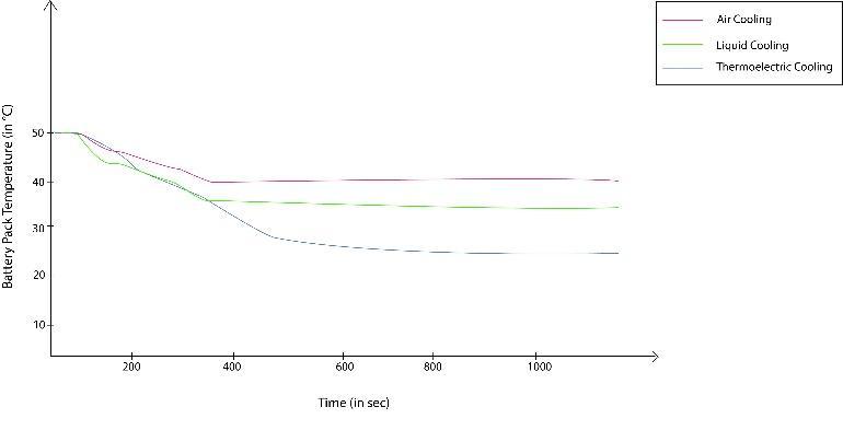
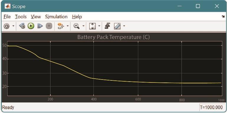
Fig.8 Comparison of different Thermal Management system for Battery Pack
4.EmergingSmartTechnologiesinCooling
Newcoolingtechnologiesarepavingtheirwayintomaking the cooling system for electric vehicles cost efficient and performanceoriented.Afterundergoingextensiveresearch practices,somemoderncoolingtechnologieshaveemerged whichareasfollows:
Volume:09Issue:12|Dec2022 www.irjet.net p-ISSN:2395-0072 © 2022, IRJET | Impact Factor value: 7.529 | ISO 9001:2008 Certified Journal | Page1234
4.1
International Research Journal of Engineering and Technology (IRJET) e-ISSN:2395-0056
Volume:09Issue:12|Dec2022 www.irjet.net p-ISSN:2395-0072
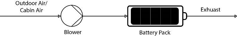
CabinAirCooling
Interaction between powertrain and cabin thermalmanagementsystemsisoneofthenovelaspectsofelectric cars.Thistechnologyworkswiththepreconditionedairin thecabinofthevehiclewhichprovidesanexternalaidtothe coolingofthebatteryandprovestobeanefficientwayof improving thermal stability. Further it has found usage in speedingupfastpowercharging.
Fig.9 Cabin Air Cooling
4.2 IndependentAirCooling
Thissystemfollowssimilaritytocabinaircooling.Itconsists of an evaporator that removes heat from the battery. Refrigerantgetsevaporatedatlowtemperatureandabsorbs heat.Thus,batterygetscooledbelowcabintemperature.
4.3 DirectRefrigerantCooling
The direct refrigerant connects an evaporator plate in parallelwiththecurrentevaporatorofvehicleaircondition. Evaporatorplateshavedirectcontactwiththebatteryplate.
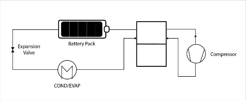
Fig.11 Heat Pipe Cooling
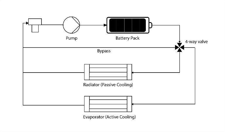
4.5 CombinationalLiquidCoolingSystem
This system has four modes: bypass with heater modes, passivecoolingandactivecooling.Passivecoolingismost preferredasithassimpleconstructionandlowpowerusage.
Fig.10 Direct Refrigerant Cooling
4.4 HeatPipeCooling
Itisyetanotherprovenemergingmilestoneinthecooling systemofelectricvehicles.Theheatpipeisanenvelopeof pipes having a capillary powder structure with sintered copperpowder.Itisusedasanevaporatorwhichabsorbs heatwhileoperationanddissipatesheatinthecondenser andbecomesliquidagain.,Incomparisontothermo-electric, a heat pipe is more reliable, because there are no moving partsandnoenergyconsumption.However,aheatpipeis unabletoheatthebatteryduetoitsfixedstructurallayout.

Fig.12 Combinational Liquid Cooling System
5. Conclusion
The rapid usage of the EV is going to increase in the near future as sustainable transport is concerned and due to which the need for development of an efficient battery coolingsystemarepriority.
Thispaperproposesonvariousbatterycoolingtechniquesof electricvehicles.AdetailedexplanationandanalysisofAir coolingsystem,LiquidcoolingsystemandThermo-Electric coolingsystemwasdone.Temperaturedropcomparisonof thelatterisalsodoneonMATLABandagraphwasobtained. Ofallsystemscomparedintheanalysis,theThermo-electric Coolingprovedtobethemostefficientandsignificantdrop inbatterytemperatureisnoted.Someemergingtechnologies inthefieldofcoolingsystemsforelectricvehiclehavebeen brieflydiscussed.Thesetechnologiesareprovingtobecome sustainableandefficientincoolingsystemsandthusprovide better thermal management. The methods and systems discussedprovideaperformanceorientedandcostefficient solutiontotheissueofthermalmanagementinbattery.
6. References
1. Zhao,RZhang,SLiuandGuJ2015Areviewofthermal performanceimprovingmethodsoflithium-ionbattery
International Research Journal of Engineering and Technology (IRJET) e-ISSN:2395-0056
Volume:09Issue:12|Dec2022 www.irjet.net p-ISSN:2395-0072
electrode modification and TMS Journal of Power Sources299
2. T M Bandhauer, S Garimella and T F Fuller 2011 A Criticalreviewofthermalissuesinlithium-ionbatteries, J.Electrochem.Soc.,158R1-R25
3. Karimi,G.;Azizi,M.;Babapoor,A.Experimentalstudyof a cylindrical lithium-ionbatterythermal management using phase change material composites. J. Energy Storage2016,8,168–174.
4. J.PereiradaCunha,P.Eames,Thermalenergystorage for low and medium temperature applications using phase change materials - A review, Appl. Energy 177 (2016)227–238.
5. A.Sharma,V.V.Tyagi,C.R.Chen,D.Buddhi,Reviewon thermalenergystoragewithphasechangematerialsand applications,Renew.Sustain.EnergyRev.13(2)(2009) 318–345
6. C. C. Chan and K. T. Chau, Modern Electric Vehicle Technology,OxfordUniversityPress,Oxford,UK
7. J. Larminie and J. Lowry, Electric Vehicle Technology Explained,JohnWileyandJohnLowry,England,UK
8. Lyu,Y.,Siddique,A.R.M.,Majid,S.H.,Biglarbegian,M., Gadsden, S. A., & Mahmud, S. (2019). Electric vehicle battery thermal management system with thermoelectric cooling. Energy Reports, 5, 822–827. doi:10.1016/j.egyr.2019.06.016
2022, IRJET | Impact Factor value: 7.529 | ISO 9001:2008 Certified Journal