International Research Journal of Engineering and Technology (IRJET) e-ISSN: 2395-0056
Volume: 09 Issue: 12 | Dec 2022 www.irjet.net p-ISSN: 2395-0072
International Research Journal of Engineering and Technology (IRJET) e-ISSN: 2395-0056
Volume: 09 Issue: 12 | Dec 2022 www.irjet.net p-ISSN: 2395-0072
1M.Tech Scholar, Dept. of Mechanical Engineering, SGSITS Indore, Madhya Pradesh, India 2Professor, Dept. of Mechanical Engineering, SGSITS Indore, Madhya Pradesh, India ***
Abstract - Concerns about traffic and pollution related to using motor cars for personal mobility are growing. The goal of this project is to develop a vehicle that might serve as a practical short-distance transportation substitute for cars. Efficient-Cycle encourages domestic transportation applications to be less reliant on fossil fuels. This project work consists of a vehicle design (tadpole design) for a tricycle that can be driven by both electrical and human energy and can seat two passengers side by side. The focus of this research is to examine four different materials AISI 1080, AISI 304, AISI 4130, and ASTM A36 (Carbon steel, Stainless steel, Alloy Steel, and Mild steel respectively) for the vehicle's frame, and to choose the best material for the frame based on its strength, weight, and cost-effectiveness. SolidWorks Version 2020 had been used to model the vehicle frame design. For the impact analysis, ANSYS Workbench Version R1 was implemented to ensure the safety and optimum material for the design analyzed using FEM. overall deformation, the highest stress, the highest strain, and the safety factor are all used to derive the result. After analyzing all the materials on the vehicle frame AISI 4130 steel performed the best for the vehicle. The material should have better results in terms of overall deformation, the highest stress, the highest strain, and the safety factor for the drivers, according to the results. It is also a lightweight, medium-cost material
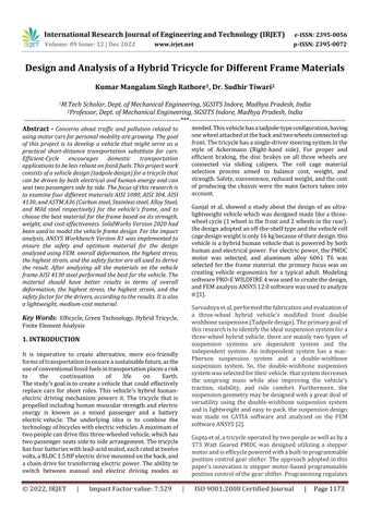
needed.Thisvehiclehasatadpole-typeconfiguration,having onewheelattachedatthebackandtwowheelsconnectedup front.Thetricyclehasasingle-driversteeringsysteminthe style of Ackermann (Right-hand side). For proper and efficient braking, the disc brakes on all three wheels are connected via sliding calipers. The roll cage material selection process aimed to balance cost, weight, and strength.Safety,convenience,reducedweight,andthecost of producing the chassis were the main factors taken into account.
Gunjal et al, showed a study about the design of an ultralightweightvehiclewhichwasdesignedmadelikeathreewheelcycle(1wheelinthefrontand2wheelsintherear). thedesignadoptedanoff-the-shelftypeandthevehicleroll cagedesignweightisonly16kgbecauseoftheirdesign.this vehicleisahybridhumanvehiclethatispoweredbyboth humanandelectricalpower.Forelectricpower,thePMDC motor was selected, and aluminum alloy 6061 T6 was selected for the frame material. the primary focus was on creating vehicle ergonomics for a typical adult. Modeling softwarePRO-EWILDFIRE4wasusedtocreatethedesign, andFEManalysisANSYS12.0softwarewasusedtoanalyze it[1].
Words: Efficycle,GreenTechnology,HybridTricycle, FiniteElementAnalysis
KeyIt is imperative to create alternative, more eco-friendly formsoftransportationtoensureasustainablefuture,asthe useofconventionalfossilfuelsintransportationplacesarisk to the continuation of life on Earth. Thestudy'sgoalistocreateavehiclethatcould effectively replace cars for short rides. This vehicle's hybrid humanelectric driving mechanism powers it. The tricycle that is propelledincludinghumanmuscularstrengthandelectric energy is known as a mixed passenger and a battery electricvehicle. The underlying idea is to combine the technologyofbicycleswithelectricvehicles.Amaximumof twopeoplecandrivethisthree-wheeledvehicle,whichhas twopassengerseatssidetosidearrangement.Thetricycle hasfourbatterieswithlead-acidsealed,eachratedattwelve volts,aBLDC1.5HPelectricdrivemountedontheback,and achaindrivefortransferringelectricpower.Theabilityto switch between manual and electric driving modes as
Sarvadnyaetal,performedthefabricationandevaluationof a three-wheel hybrid vehicle's modified front double wishbonesuspension(Tadpoledesign).Theprimarygoalof thisresearchistoidentifytheidealsuspensionsystemfora three-wheel hybrid vehicle. there are mainly two types of suspension systems are dependent system and the independent system. An independent system has a macPherson suspension system and a double-wishbone suspension system. So, the double-wishbone suspension systemwasselectedfortheirvehicle.thatsystemdecreases the unsprung mass while also improving the vehicle's traction, stability, and ride comfort. Furthermore, the suspensiongeometrymaybedesignedwithagreatdealof versatility using the double-wishbone suspension system andislightweightandeasytopack.thesuspensiondesign was made on CATIA software and analyzed on the FEM softwareANSYS[2]
Guptaetal,atricycleoperatedbytwopeopleaswellasbya 373 Watt Geared PMDC was designed utilizing a stepper motorandisefficyclepoweredwithabuilt-inprogrammable positioncontrolgearshifter.Theapproachadoptedinthis paper's innovation is stepper motor-based programmable positioncontrolofthegearshifter.Programmingregulates
2022, IRJET | Impact Factor value: 7.529 | ISO 9001:2008 Certified Journal |

International Research Journal of Engineering and Technology (IRJET) e-ISSN: 2395-0056
Volume: 09 Issue: 12 | Dec 2022 www.irjet.net p-ISSN: 2395-0072
thespeedofthemotors,whichinturnregulatestheposition ofthegearchanger.Itenablesmoreautomaticcontrolofthe vehicleandlessenstheeffortrequiredfromthedriver.The emphasishasbeenplacedontheexcellentperformance,low maintenance,safety,andaffordabilityofthedesign.SteelST 52.3OverAISI1080waschosenforthevehicle'smaterial becauseitistoolightweight,extremelyductile,andstrong. Solidworks was used to simulate the design, while Ansys softwarewasusedforanalysisfortestssuchasfrontimpact, sideimpact,rearimpact,androlloverimpact[3]
Chawla et al, displayed the suspension system design and hardpointoptimizationofathree-wheelhybridvehicle.The simulationmodelingand analysisofsuspensiongeometry arecoveredinthisstudy.Thesuspensionwascreatedwith superiorhandlingandcomfortforbothdriversinmind.To replace the rickshaws that lack both front and rear suspension systems. So, they enhanced the suspension designbychoosinghardpointoptimization(cambercurve, bumpsteercurve,casterchangerate,etc),Damperdesign, andSpringdesign.Thispaper'smajorobjectiveistoimprove the rolling and dive characteristics of suspension systems while maintaining good vehicle handling, a good balance betweendriveranddrivestability,increaseddurabilityand reliability,andmaximumwheeltravel[4].
Abhayetal,demonstratednumerouslightweighttechniques, including lightweight seats, wheels, and steering. This paper'sinnovationusesUVjointsinthefrontaxletoprovide the vehicle with independent suspension and front-wheel drive, which are hardly ever seen on the front of a car, makingiteasierforthecartoclimbhillsandresiststocksat the same time. The tadpole design was adopted with two wheelsinfrontandonewheelintheback,andtheychose various approaches for turning radius, stability, handling, andeaseofmaneuvering.Theyalsoreducedtheweightof thevehiclebychoosinglightweightequipmentandmaterials thatwerestillstrong,andtheyoptimizeditforalightweight vehiclesothematerialAISI1080wasselected.Thedesign was simulated and analyzed on SOLIDWORKS, and it underwent various tests including front, side, rear, and rolloveranalyses[5].
Aphaleetal,performedthedesignandanalysisofarollcage foranelectrichybridtricycledemonstratingimprovingthe rollcage'sstructuralintegrityandoverallattractiveness,so thevehicleframegivesbettersafetyforthedriversaswellas ergonomic design and strength. Also, they selected the varioustypeofmaterialsfortheframeaftercomparingtheir mechanicalandchemicalpropertiestheyselectedHSLA340 material for the frame of the vehicle due to its strong strength,lowcarboncontent,and exceptional weldability. afterthat,theypreparedthedesignintheCADmodelnamely PTCCreo3.0,andFEAwasundertakeninANSYSWorkbench 15[6].
Prakashetal,developedahuman-poweredelectrichybrid power tricycle to lessen reliance on fossil fuels for
transportation to a short distances. This paper aims to visualize, design, and fabrication the tricycle known as efficycle. Sofirsttheyfocusedonthechassisdesignofthe vehicle and assumed considering the constraints and dimensions then a CADwas implemented to design the vehiclesonsoftwarePTCCreo3.0thenensurethesafetyof rollcage/framedesignthevehiclechassistestedbyusing FEA software ANSYS V16.2. In this, they calculated the impactanalysisforfront,side,androlloverimpactsinterms oftotaldeformation,max.stress,max.strain,andfactorof safety.ThematerialAISI1080wasusedfortheframeofthe vehicle. After completing the design and simulation the vehiclewasfabricated.Thekeyparameterforthispaperis cost-reducing, better strength for the vehicle, and a comfortablebasefortheriders[7].
Reddyetal,designedandfabricatedanultralightvehiclethat ispoweredbybothusingelectricpoweraswellashuman power.Thisstudyalsoconcentratedontheaffordabilityand simplicityofthevehicledesign.Thedesignwasmadeusing modelingsoftwareSOLIDWORKSkeepingaviewofdrivers' ergonomicsandplacement oftheaggregatesandthenthe design was analyzed by Finite Element Method analysis softwareANSYS12.0forFrontal,Side,andRolloverimpacts analysisinformoftotaldeformation,max.stress,andmax. strain.Fortheframe,thetypeisarollcagedesign,andthe materialwasusedMildsteel(ANSI1026)withcircularpipe dimensions: OD- 30mm, ID- 24mm, Thickness- 3, and Density- 7858kg/cm3.The keyparametersforthispaper areultra-lightweight,hybridtricycles,andmechanicaldrive [8]
Thevehicle'smeasurementsarepresumptive,takinginto account the limitations and proportions based on the compactdesign.Followingtheassumptionoftheproportions, considerationwasmadetomakingthevehicleergonomicfor atypicaladult.ThevehicleisthencreatedusingSolidworks V2020.ANSYSVR1,thesoftwareforfiniteelementanalysis,is used to assess the vehicle's structural integrity. The roll cage/framedesignisadjustedforsafetyreasonsbeforebeing finalized. Several factors, including serviceability, craftsmanship,andcostreduction,weretakenintoaccount whenmodelingthevehicleframe.
The following aspects are kept in mind for the drivers' ergonomics:
Seatandsteeringangleplacements.
Thedriver'shandshouldbeabletoreachallleversand switches.
Bothdrivershavemorethanenoughheadroomand legroom.
International Research Journal of Engineering and Technology (IRJET) e-ISSN: 2395-0056
Volume: 09 Issue: 12 | Dec 2022 www.irjet.net p-ISSN: 2395-0072
The battery and BLDC motor are located behind the driver.
Table -1: Mechanicalcharacteristicsoffourmaterials[6][8].
Topreventinjuriesintheeventofanaccident, scratchprotectorsarefittedonbothsidesofthedriver.
Mechanical properties AISI 1080 AISI 304 AISI 4130 ASTM A36
Brinell Hardness 126 215 240 240
UltimateT.S. 440MPa 505MPa 560MPa 550MPa YieldT.S. 365MPa 215MPa 460MPa 250MPa Modulus of elasticity 205GPa 200GPa 210GPa 200GPa
Bulkmodulus 140GPa 134GPa 140GPa 140GPa Poisson’s ratio 0.29 0.27 0.30 0.26
Fig -1: (a)Isometricimageofthetricycle;(b)Frontimage ofthetricycle.
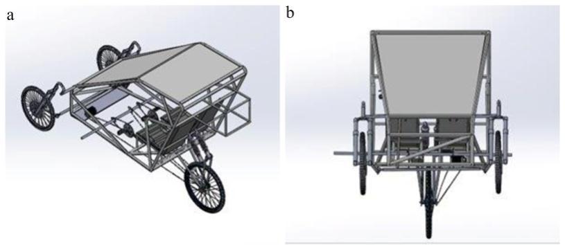
Theframedesignwascreatedwithimprovedaviationand the riders' comfort in mind. For the protection of riders, additionalbatteryplacement,suspension,andsittingareas werecreatedinadditiontothisroofcoveringconfiguration. The frame pipes are hollow with the dimension of outer diameter25.4,anInnerdiameter21.4,andathicknessof2 mm
Shear modulus 80GPa 74GPa 80GPa 79.3GPa
Density 7870 Kg/m3 8000 Kg/m3 7850 Kg/m3 7850 Kg/m3
Table -2: Chemicalcharacteristicsoffourmaterials[6]–[8]
Chemical properties AISI 1080 % AISI 304 % AISI 4130 % ASTM A36 %
Iron 98-99 66.74 –71.24 97.03 –98.22 98
Carbon 0.75 –0.88 0.07 0.280 –0.330 0.25 –0.29
Manganese 0.60-0.90 2 0.40 –0.60 1.03
Sulphur 0.05 (max.) 0.03 0.040 0.05
Phosphorous 0.04 ((max.) 0.05 0.035 0.04
Chromium - 17.5 –19.5 0.80 –1.10 -
Nickel - 8–10.5 - -
Fig -2: Frameofthevehicle.
InthisstudytherearefourmaterialsAISI1080,AISI304,AISI 4130,andASTMA36wereselectedforthevehicleframe.For thedesignoftheirvehicleframes,variousstudypublications havechosenvariousmaterialsbasedontheirmechanicaland chemical qualities. To determine which material is best suitableforavehicleframeintermsofstrength,lightweight, andaffordability,wechosefourcommonmaterialsthatwere chosen in earlier research for this project and ran them throughANSYSusingfiniteelementanalysis.Belowtable1& 2showtheMechanicalandChemicalmaterialcharacteristics
Silicon - 1 0.15 –0.30 0.280
Nitrogen - 0.11 -Molybdenum - - 0.15 –0.30 -
Copper - - - 0.20
After the CAD model of the vehicle, and the frame was finished, four materials were chosen andsubjectedtoFEA study in the form of frontal impacts, side impacts, and rollover impact analysis to guarantee driver safety and
Factor value: 7.529 | ISO 9001:2008 Certified Journal |
International Research Journal of Engineering and Technology (IRJET) e-ISSN: 2395-0056
Volume: 09 Issue: 12 | Dec 2022 www.irjet.net p-ISSN: 2395-0072
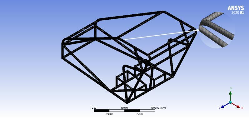
improvetheframe'sstrength.Foranalyzingalltheresultson theframeandtheframemeshedontheANSYSWorkbenchto getbetterandmorepreciseresults.WhenFramewasmeshed on the software automatically selected the element size (20.33mm)andthedefaultmethodcoarsemeshbut made manually selected a 5 mm element size and fine meshing because the more the number of elements on the frame producedpreciseresults.
Fig -3: MeshingFrameofthetricycle
Considerations&Assumptiontocalculatefrontalimpact,itis estimatedthatthevehiclewillreachfinalzerovelocityin0.6 secondsatatopspeedof35kmph.Thevehicleisestimated toweigh150kg,whilethetwodriverseachweigh90kg.Any impact could be made to the vehicle, whether it is unintentionalordeliberate.Findingimpactforcesanddoing impactanalysisareconsideredessentialsincethevehicleis anticipatedtowithstandtheimpact.
Forthefrontalimpactforcecalculation:overallweight(m)is calculatedas150+90+90kg,whichis330kg,time(T)is0.6 seconds, starting velocity (u) is 35 kilometers per hour or 9.722m/s,andendingvelocity(v)is0kilometerperhour.In addition,thefrontimpactforceisgivenbyF=mdV/dT[7]= 330*9.723/0.6 or5347.65N.Amaximumforceof5347.65 Nmustbetakenintoaccountforfrontalimpact.
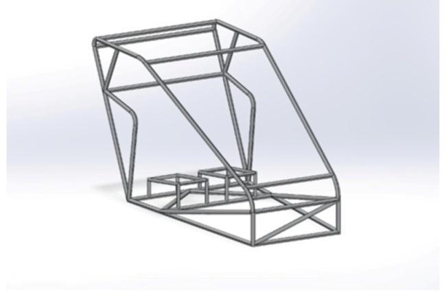
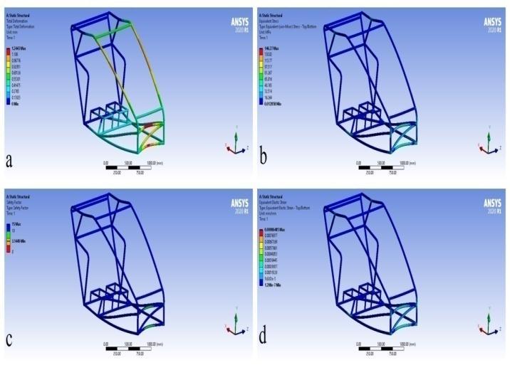
The ANSYS Workbench platform is used to run the simulation. Results for overall deformation, max. stress, safety factor, and max. strain are illustrated in figures 4(a),(b),(c)&(d).Followingarethemeasuredvaluesshown inbelowtable:
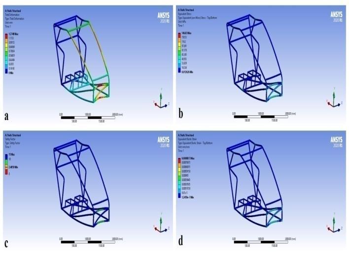
overall Deformation Max.stress Safetyfactor MaxStrain
1.2748mm 146.83MPa 2.4859 0.0008873
Fig -4:(a)overalldeformation;(b)Max.stress distribution;(c)Safetyfactor(d)Max.strain.
The ANSYS Workbench platform is used to run the simulation. Results for overall deformation, max. stress, safety factor, and max. strain are illustrated in figures 5(a),(b),(c)&(d).Followingarethemeasuredvaluesshown inbelowtable:
overall Deformation Max.stress Safetyfactor MaxStrain 1.307mm 147.66MPa 1.45 0.00091178
Fig -5:(a)overalldeformation;(b)Max.stress distribution;(c)Safetyfactor(d)Max.strain.
The ANSYS Workbench platform is used to run the simulation. Results for overall deformation, max. stress, safety factor, and max. strain are illustrated in figures 6(a),(b),(c)&(d).Followingarethemeasuredvaluesshown inbelowtable:
International Research Journal of Engineering and Technology (IRJET) e-ISSN: 2395-0056
Volume: 09 Issue: 12 | Dec 2022 www.irjet.net p-ISSN: 2395-0072
overall Deformation Max.stress Safetyfactor MaxStrain
1.2443mm 146.27MPa 3.14 0.00086485
secondat35kilometersperhouristhemaximumspeed.The vehicleisestimatedtoweigh150kg,although eachofthe twodriversonlyweighs90kilograms.Anyeffectcouldbe madetothevehicle,whetheritisunintentionalordeliberate.
Forthesideimpactforcecalculation:overallweight(m)is calculatedas150+90+90kg,whichis330kg,impacttime (T) is 1 second, starting velocity (u) is 35 kilometers per houror9.722m/s,andendingvelocity(v)is0kilometerper hour. In addition, the side impact force is given by F = m dV/dT[7]=330*9.722/1or3208.26N.Amaximumforce of3208.26Nmustbetakenintoaccountforsideimpact.
The ANSYS Workbench platform is used to run the simulation. Results for overall deformation, max. stress, safety factor, and max. strain are illustrated in figures 8(a),(b),(c)&(d).Followingarethemeasuredvaluesshown inbelowtable:
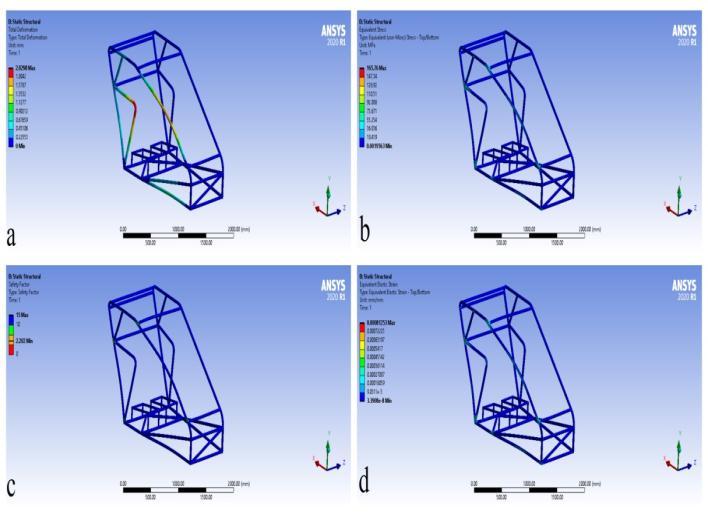
Fig -6:(a)overalldeformation;(b)Max.stress distribution;(c)Safetyfactor(d)Max.strain
ASTM A36
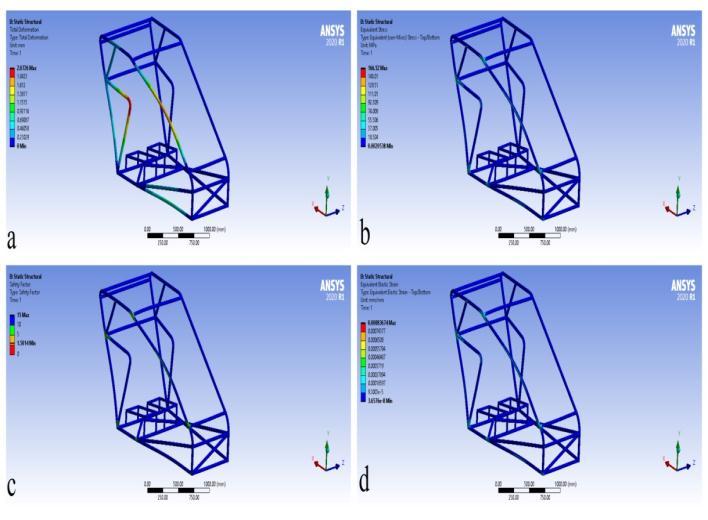
The ANSYS Workbench platform is used to run the simulation. Results for overall deformation, max. stress, safety factor, and max. strain are illustrated in figures 7(a),(b),(c)&(d).Followingarethemeasuredvaluesshown inbelowtable:
overall Deformation Max.stress Safetyfactor MaxStrain 1.3072mm 148.48MPa 1.68 0.00091432
overall Deformation
Max.stress Safetyfactor MaxStrain 2.0298mm 165.76MPa 2.20 0.00081253
Fig -7:(a)overalldeformation;(b)Max.stress distribution;(c)Safetyfactor(d)Max.strain.
Considerations&Assumptiontocalculatesideimpact,itis estimatedthatthevehiclewillreachfinalzerovelocityin1
Fig -8:(a)overalldeformation;(b)Max.stress distribution;(c)Safetyfactor(d)Max.strain.
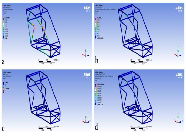
The ANSYS Workbench platform is used to run the simulation. Results for overall deformation, max. stress, safety factor, and max. strain are illustrated in figures 9(a),(b),(c)&(d).Followingarethemeasuredvaluesshown inbelowtable:
overall Deformation
Max.stress Safetyfactor MaxStrain 2.0767mm 166.15MPa 1.29 0.00083485
International Research Journal of Engineering and Technology (IRJET) e-ISSN: 2395-0056
Volume: 09 Issue: 12 | Dec 2022 www.irjet.net p-ISSN: 2395-0072
overall Deformation Max.stress Safetyfactor MaxStrain 2.0726mm 166.52MPa 1.50 0.00083674
Fig -9:(a)overalldeformation;(b)Max.stress distribution;(c)Safetyfactor(d)Max.strain
The ANSYS Workbench platform is used to run the simulation. Results for overall deformation, max. stress, safety factor, and max. strain are illustrated in figures 10(a),(b),(c)&(d).Followingarethemeasuredvaluesshown inbelowtable:
overall Deformation Max.stress Safetyfactor MaxStrain 1.9838mm 165.48MPa 2.77 0.00079184
Fig -11:(a)overalldeformation;(b)Max.stress distribution;(c)Safetyfactor(d)Max.strain.
Tocalculatetheroll-overimpact, Thevehicleisthoughtto have fallen from a height of 6 feet on its roll-over hoop membersintothegroundortheroad.itisexpectedthatthe vehiclewillreachits35-kilometer-per-hourmaximumspeed in6secondsandthatitsultimatevelocitywillbezero.The vehicleisestimatedtoweigh150kg,althougheachofthetwo driversonlyweighs90kilograms
Fortherolloverimpactforcecalculation:theoverallweight (m)iscalculatedas150+90+90kg,whichis330kg,time.In addition, the Rollover impact force is given by F = {(N*W/2)*h} [7] =[330*9.81*1.83/2] or 2962.12N. A maximumforceof2962.12Nmustbetakenintoaccountfor rolloverimpact.
Fig -10:(a)overalldeformation;(b)Max.stress distribution;(c)Safetyfactor(d)Max.strain.
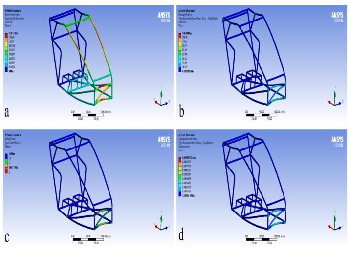
The ANSYS Workbench platform is used to run the simulation. Results for overall deformation, max. stress, safety factor, and max. strain are illustrated in figures 11(a),(b),(c)&(d).Followingarethemeasuredvaluesshown inbelowtable:
The ANSYS Workbench platform is used to run the simulation. Results for overall deformation, max. stress, safety factor, and max. strain are illustrated in figures 12(a),(b),(c)&(d).Followingarethemeasuredvaluesshown inbelowtable:
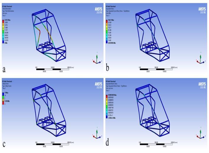
overall Deformation
Max.stress Safetyfactor MaxStrain 1.2132mm 113.41MPa 3.21 0.00057389
International Research Journal of Engineering and Technology (IRJET) e-ISSN: 2395-0056
Volume: 09 Issue: 12 | Dec 2022 www.irjet.net p-ISSN: 2395-0072
overall Deformation Max.stress Safetyfactor MaxStrain 1.1837mm 113.38MPa 4.0573 0.00056007
Fig -12:(a)overalldeformation;(b)Max.stress distribution;(c)Safetyfactor(d)Max.strain.
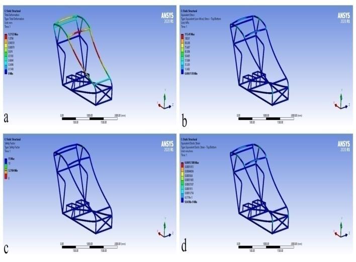
The ANSYS Workbench platform is used to run the simulation. Results for overall deformation, max. stress, safety factor, and max. strain are illustrated in figures 13(a),(b),(c)&(d).Followingarethemeasuredvaluesshown inbelowtable:
overall Deformation Max.stress Safetyfactor MaxStrain 1.2444mm 113.47MPa 1.89 0.00058854
Fig -14:(a)overalldeformation;(b)Max.stress distribution;(c)Safetyfactor(d)Max.strain
6.4 Analysis of frame on ASTM A36
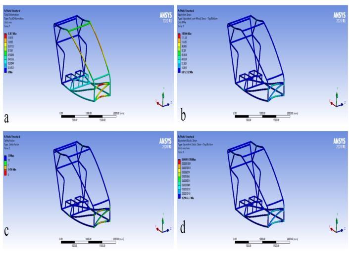
The ANSYS Workbench platform is used to run the simulation. Results for overall deformation, max. stress, safety factor, and max. strain are illustrated in figures 15(a),(b),(c)&(d).Followingarethemeasuredvaluesshown inbelowtable:
overall Deformation Max.stress Safetyfactor MaxStrain 1.2452mm 113.53MPa 2.20 0.00058888
Fig -13:(a)overalldeformation;(b)Max.stress distribution;(c)Safetyfactor(d)Max.strain
AISI 4130
The ANSYS Workbench platform is used to run the simulation. Results for overall deformation, max. stress, safety factor, and max. strain are illustrated in figures 14(a),(b),(c)&(d).Followingarethemeasuredvaluesshown inbelowtable:

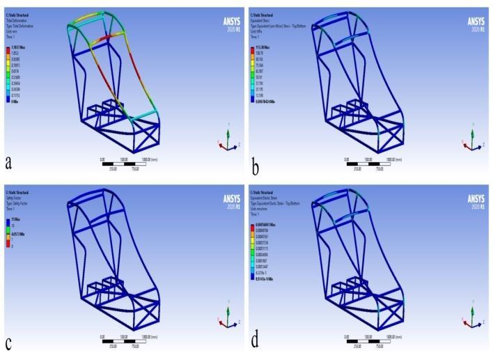
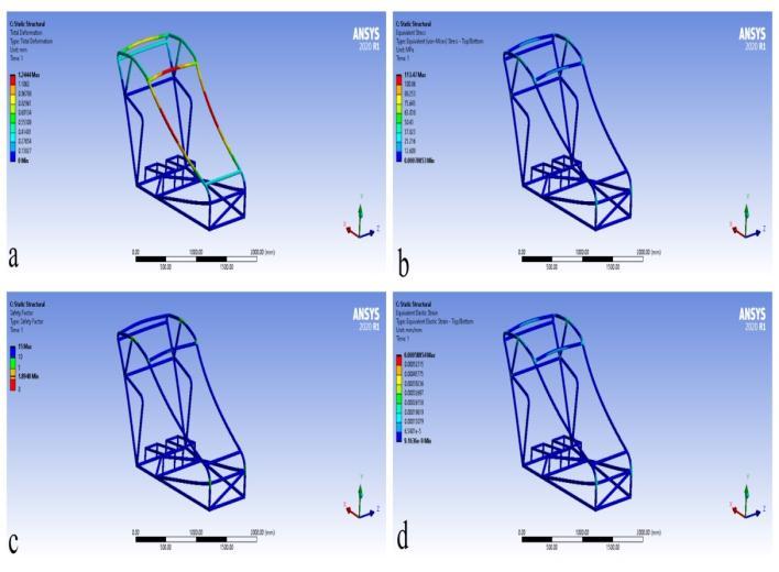
Fig -15:(a)overalldeformation;(b)Max.stress distribution;(c)Safetyfactor(d)Max.strain.
International Research Journal of Engineering and Technology (IRJET) e-ISSN: 2395-0056
Volume: 09 Issue: 12 | Dec 2022 www.irjet.net p-ISSN: 2395-0072
By contrasting the present findings with those from other research,thefrontalimpact,sideimpact,androlloverimpact analysisareallvalidatedintheformofoveralldeformation, max. stress, safety factor, and max. strain. Present study resultsarecomparedwithJayPrakashetal.[7]wherethey calculated applied forces on the vehicle frame for frontal impact, side impact, and rollover impact are 5348.16 N, 3208.59N,and1438.8Nrespectively.Tableno.3,4,and5 showedresultscomparisonswithpreviousstudies,andits shows that present study results are more reliable and somewhereneartopreviousstudies.
Table -3: Comparisonofpreviousstudyfrontalimpact resultinformofdeformation,stress,safetyfactor,and strainwithpresentstudy
Material s Authors Overall deformat ion
AISI 1080 Jay Prakash et al.[7]
Max. stress Safety factor Max. strain
4.341 mm 146.3 7MPa 2.49 0.000883 27
AISI 1080 Present study 1.2748 mm 146.8 3MPa 2.48 0.000887 3
AISI 304 Present study 1.307 mm 147.6 6MPa 1.45 0.000911 78
AISI 4130 Present study 1.2443 mm 146.2 7 MPa 3.14 0.00086 485
ASTM A36 Present study 1.3072 mm 148.4 8MPa 1.68 0.000914 32
Table -4: Comparisonofpreviousstudysideimpactresult informofdeformation,stress,safetyfactor,andstrainwith presentstudy.
Material s Authors Overall deformat ion
AISI 1080 Jay Prakash et al.[7]
Max. stress Safety factor Max. strain
0.5236 mm 29.20 7MPa 12.5 0.000161 9
AISI 1080 Present study 2.0298 mm 165.76 MPa 2.20 0.000812 53
AISI 304 Present study 2.0767 mm 166.15 MPa 1.29 0.000834 85
AISI 4130 Present study 1.9838 mm 165.4 8 MPa 2.77 0.000791 84
ASTM A36 Present study 2.0726 mm 166.52 MPa 1.50 0.000836 74
Table -5: Comparisonofpreviousstudyrolloverimpact resultinformofdeformation,stress,safetyfactor,and strainwithpresentstudy.
Material s Authors Overall deformat ion
AISI 1080 Jay Prakash et.al.[7]
Max. stress Safety factor Max. strain
3.007 mm 70.20 5MPa 5.19 0.00043 5
AISI 1080 Present study 1.2132 mm 113.41 MPa 3.21 0.00057 389
AISI 304 Present study 1.2444 mm 113.47 MPa 1.89 0.00058 854
AISI 4130 Present study 1.1837 mm 113.3 8 MPa 4.05 0.00056 007
ASTM A36 Present study 1.2452 mm 113.53 MPa 2.20 0.00058 888
TheEffi-cycleisanEco-greenvehiclewithanelectricmotor thatwasdevelopedto reducenoise and air pollution.The focushasbeenlaidtoselectthebest-suitedmaterialforthe vehicle frame to give better strength, lightweight, and economical material. In this project work, Four materials usedfrompreviousresearchAISI1080,AISI304,AISI4130, andASTMA36(Carbonsteel,Stainlesssteel,AlloySteel,and Mildsteelrespectively)fortheframedesigningofEffi-cycle. After successfully analyzing these four materials on the vehicle frame Finite Element Analysis is calculated in the formofoveralldeformation,maximumstress,thesafetyof factor,andmaximumstrainforallimpactloads.Concluded thatthebest-suitedmaterialisAISI4130fortheEffi-cycle becauseofthestrengthaspectaswellastheeconomicpoint of view. This AISI 4130 material produced the minimum impactloadsascomparedtoothersteel materials.Sothis researchprovidedthevehiclewithmorestrengthandsafety factorsforbothdrivers.
[1] S. U. Gunjal, G. D. Sonawane, S. P. Awate, and D. R. Satpute. (2014) "Design, Analysis & Fabrication of Efficycle: A Hybrid Tricycle." International Journal of EngineeringTrendsandTechnology(IJETT)–Volume17 Number8–Nov2014
[2] Thakare, Sarvadnya Ajinkya, Prasad C. Antapurkar, Divyaj S. Shah, P. R. Dhamangaonkar, and S. N. Sapali. (2015) "Design and analysis of modified front double wishbone suspension for a three wheel hybrid vehicle."Proceedings of the World Congress on Engineering2015VoumelIIsystem3,6.
International Research Journal of Engineering and Technology (IRJET) e-ISSN: 2395-0056
Volume: 09 Issue: 12 | Dec 2022 www.irjet.net p-ISSN: 2395-0072
[3] Gupta,UpendraS.,SumitChandak,andDevashishDixit. (2015) "Design of Efficycle-Human Powered Hybrid Tricycle with inbuilt Programmable Position Control GearShifterusingStepperMotor."InternationalJournal ofEngineeringTrendsandTechnology(IJETT)–Volume 19Number3–Jan2015.
[4] Chawla, Gomish, and Shivam Setia. (2016) "Designing andhardpointoptimizationofsuspensionsystemofa three-wheel hybrid vehicle."International Journal of AerospaceandMechanicalEngineeringVolume3–No.1, February2016.
[5] Tiwari,Abhay,I.Jaswal,SuliptDas,andA.Singh.(2017) "Design of Efficycle-Human Powered Light Weight Hybrid Tricycle with Inbuilt Rear Wheel Steering and Use of Universal Joint in Front Axle."Advances in AutomobileEngineering6,no.167:2.
[6] Siddharth Aphale, and Pradnesh Lachake. (2017) "DesignandAnalysisofRollCageforanElectricHybrid Tricycle."International Journal of Engineering Trends and Technology (IJETT) – Volume-44 Number-2February2017Carbon2,no.1:3
[7] Srivastava, Jay Prakash, Dheeraj Joshi, L. Vivek, G. Sai Manish,G.Sravan,K.Enosh,E.NareshNaik,K.Vamshi Krishna,M.Prem,andK.Dayanand.(2019)"Designand FabricationofHuman-ElectricHybridPowerTri-Cycle." InIOP Conference Series: Materials Science and Engineering,vol.653,no.1,p.012004.IOPPublishing, 2019.
[8] Reddy,M.Varun,B.RohithKumar,P.PraveenKumar,Y. VijayVardhan,andA.Ravindra.(2021)"Design,analysis andfabricationofeffie-cycle:Ahybridtadpolevehicle." InAIP Conference Proceedings, vol. 2317, no. 1, p. 040015.AIPPublishingLLC,2021.
2022, IRJET | Impact Factor value: 7.529 | ISO 9001:2008 Certified Journal |