International Research Journal of Engineering and Technology (IRJET) e-ISSN:2395-0056

Volume: 09 Issue: 12 | Dec 2022 www.irjet.net p-ISSN:2395-0072
International Research Journal of Engineering and Technology (IRJET) e-ISSN:2395-0056
Volume: 09 Issue: 12 | Dec 2022 www.irjet.net p-ISSN:2395-0072
1
2
Bhopal,
***
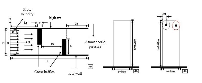
Abstract- Heat exchangers can have flat or corrugated plates for the wall material, as well as cylindrical or variable section ducts with baffles of varying shapes and sizes. The purpose of this study is to demonstrate the effectiveness of baffles in creating recirculation zones in a channel by causing a disturbance in the fluid flow and, consequently, the convective heat exchange instability. The use of hydrogen and forced convection creates a turbulence in the flow. The baffles are installed on the vertical and horizontal sides of a rectangular channel at angles of 30 degrees, 45 degrees, and 60 degrees, respectively. Dispersion patterns of the Nusselt number, along with velocity fields and axial velocity profiles, are displayed. Use of baffles results in the creation of recirculation zones, which in turn disrupt the natural flow of convective heat exchange. Sloped at an angle of 30 degrees, the slanted section of the baffle increases the Nusselt number by nearly 26%.
Key words: Convectiveinstability,Forcedconvection,rectangularduct,Baffle,Flowdisturbance,Hydrogen.
Introduction:
Aheatexchangerisadevicethatallowsatransferofthermalenergybetweenatleasttwobodies(solids,liquidsorgases). Most of the time, these are fluids. These fluids may be in indirect or direct contact, i.e. separated or not by a generally metallic wall. However, this definition is not general because there are a multitude of types of exchangers, with geometries, configurations and even modes of operation which can be very different. Thus, the selection of a heat exchanger for a particular application depends on a number of factors, including the fluids' temperature and pressure range, their thermophysical characteristics, maintenance requirements, and congestion. It is obvious that having a welladapted,well-sized,well-madeandwell-usedheatexchangerimprovesthethermalefficiencyofthisdevice.
The improvement of the performance of heat exchangers is aimed at the mechanisms of intensification of convective transfers, as evidenced by the increasing number of studies carried out on the effect of inserting the elements into a tubular space which would be of appreciable contribution to new designs of thermal appliances or to optimise the economicintheoperationofheattransfernetworks.
Themostcommonlyusedintensificationtechniquesaretheso-called"passive"ones,theyconsistinthemajorityofcases inincreasingtheheatexchangesurfacesinordertointensifyheattransfers.Oneofthemostimportantmethodsistouse extensiveelementssuchasbafflesinsidetheheatexchangerchannel.
The various sizes, positions, and orientations of obstructions inside exchanger tubes have been the focus of several scientificworks,accordingtotheliterature.Inordertobettercomprehendconvectiveflowinarectangularpipe:
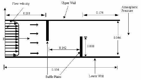
Pethkool et al. [1], For a Reynolds number ranging from 5500 to 60000, it was examined how blocking factor (e/D) a corrugatedhelical tubewith monophasicturbulentwaterflowthatwasinfluenced convectiveheattransfer.The findings demonstrate that the performance factor significantly rises with an increase in blocking factor and reaches a value of about 232 percent when compared to a smooth tube.[10], the evaluation of the Nusselt number is carried out by the followingformula: (I.1)
International Research Journal of Engineering and Technology (IRJET) e-ISSN:2395-0056
Volume: 09 Issue: 12 | Dec 2022 www.irjet.net p-ISSN:2395-0072
Promvonge's experimental work.[2],undertakentoassessthe forcedconvectionheattransferforturbulent airflowina channel with a 60°-V multiple deflector turbulator., the Reynolds number is between 5000 and 25000, and the blocking factorvariesbetween0.1and0.3.TheNusseltnumberisevaluatedbythefollowingempiricalformula: (I.2)
Fig -2 Twistedbands
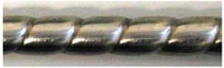
Demartini etal.[3],Weundertakenanintriguingcomputationalandexperimentalanalysisofflattransversebafflesfora turbulent airflow regime in a two-dimensional heat exchange channel. Additionally, they discovered that this issue is crucial in the area of heat exchangers since it affects flow characterisation, pressure distribution, and the potential existenceandgrowthofrecirculation’s.Areasonablydenserecirculationzoneisvisibleabove eachchannel’sfacetsandis movinginthedirectionofswallowontheprofilesandaxialvelocitydistribution.Theimpactoftheflowfield'sdistortion increases as the flow approaches the first channel. The biggest disruption is seen upstream of the second channel, they alsodemonstrated.
Fig -3 ChannelconfigurationstudiedbyDemartinietal,[3]
Bensenouci et al. [4], Forced convection heat transfer in a rectangular pipe with baffles was investigated by numerical modelling. Convective heat exchange is promoted by the requirement to insert rows of fins and baffles in the vein of the emolument in heat exchangers. Research has revealed that the vertical portions nearest to the baffles are better heated thanthedistantverticalparts.Thedistributionofthetemperaturefieldinthechannelfurthersupportsthisobservation.
International Research Journal of Engineering and Technology (IRJET) e-ISSN:2395-0056
Volume: 09 Issue: 12 | Dec 2022 www.irjet.net p-ISSN:2395-0072
Mennietal.[5],numericallystudiedthecomparisonbetweentwodifferentformsoffinsandtransversebaffles.Thefirstis rectangularwithasharptip,andthesecondrectangulariswitharoundedtip.Inahorizontal,two-dimensionalpipewitha rectangularcross-section,theyareplacedinoverlap.Thefluid(air)isoftheNewtoniantype,incompressiblewithconstant thermo-physical properties. The flow regime is considered permanent and purely turbulent. For a Reynolds number of between5000and20000,calculationsareconducted.Theexaminationofthedatashowedthattheadditionofrectangular type baffles without rounding provides a significant increase in speed and improves the intensity of heat transmission whenusedwithrectangularchianes.
b-Rectangularwingwitharoundedtip Fig -4 Testsection
Tsay et al. [6], The improvement of heat transmission of a flow in a channel with a vertical channel was quantitatively examined.In the100–500 Reynolds number range,the impact ofchannel sizeand back coatingson the flowstructureis thoroughlyinvestigated.Theyobservedthatbyaddingabaffletotheflow,thetypicalNusseltnumbercouldbeincreased by190%.Theyalsonoticedthatthechannel’spositionaffectsthethermalanddynamicpropertiesoftheflow.
Bilenetal.[7],conductedanexperimentalstudyonthethermalandhydrauliccharacteristicsofturbulentairflowintubes withdifferentgrooveforms(circular,trapezoidal,andrectangular),withReynoldsnumbersrangingfrom10000to30000. Whencomparingthefindingstoasmoothtube,thecirculargrooveconfigurationincreasesheattransmissionby63%,the trapezoidalgrooveconfigurationby58%,andtherectangulargroovedtubeby47%. Theauthorsattributedtherelatively poor thermal performance of rectangular grooves to the appearance of stagnation or recirculation zones in this configuration. The relativelysimilarthermal performanceoftrapezoidal andcirculargrooves,despitea lowernumberof trapezoidalgrooves,isexplainedbygreaterflowdisturbanceinthisconfiguration.
The Fluent tool:
Simulationsbasedoncomputationalfluiddynamics(CFD)areusedtosimulate,visualise,andanalysefluidflowsandheat fluxes.Itenablesuserstooptimisetheperformanceofnewconcepts,whilereducingthemarketingcycle,associatedrisks andcosts.
Simulationofthethermalanddynamicbehaviouroftherectangularexchangerchannelmenu:
Import Geometry (msh):
The dimension of the geometry is in 2D, for this the choice of 2D seems the most appropriate for our simulation, so it is chosenasfollows:
International Research Journal of Engineering and Technology (IRJET) e-ISSN:2395-0056
Volume: 09 Issue: 12 | Dec 2022 www.irjet.net p-ISSN:2395-0072
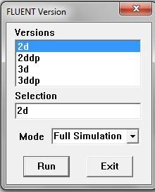
Fig -5 OpentheFluentVersion

Import geometry: FileReadCase
Fig -6 ImportingGeometry
Tostartthesimulation,youmustimportthefile(*.msh)generatedunderGambit.

Checking the imported mesh: Grid Check
Thischeckswhethertheimportedmeshcontainserrors.
Fig -7 CheckingthemeshunderFluent
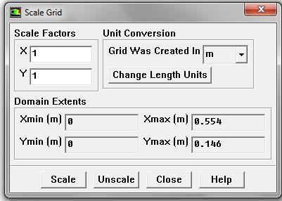
Verification of the scale: GridScale
Alwayscheckthatthedimensionsdisplayedcorrespondtothephysicaldimensionsoftheproblem.
International Research Journal of Engineering and Technology (IRJET) e-ISSN:2395-0056
Volume: 09 Issue: 12 | Dec 2022 www.irjet.net p-ISSN:2395-0072
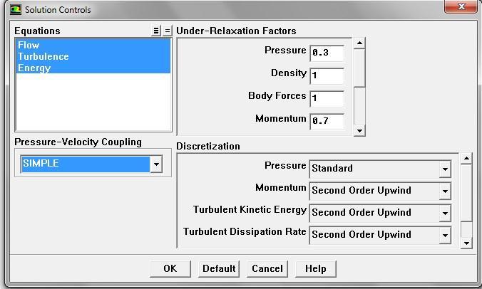
Choice of solver: DefineModelsSolver
SegregatedSolver:isthemostsuitableforincompressibleflows(fans,pumps...)
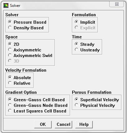
CoupledSolvers, the"coupledimplicit"and"coupled explicit"solvers,arerather reservedforcompressible flowsat high speed.
Thisisalsowheretheflowregimeischosen;permanentorunsteady
Fig -9 ChoosingtheSolverinFluent
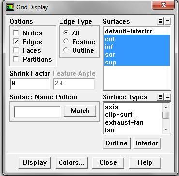
Grid display: DisplayGrid
YoucanviewthemeshanditisverygoodtochecktheboundaryconditionsdefinedbeforehandinGambit
International Research Journal of Engineering and Technology (IRJET) e-ISSN:2395-0056
Volume: 09 Issue: 12 | Dec 2022 www.irjet.net p-ISSN:2395-0072
Fig -10 DisplayingtheGridandCheckingconditions
Fig -11 SimulationDomainDisplay
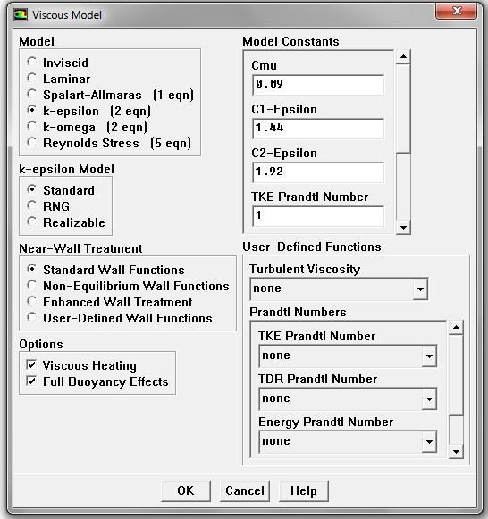
Choice of turbulence model: DefineModelsViscous
Fluentoffersdifferentmodelsofturbulentflow.Amongwhichnon-viscous,laminar,turbulentflows...etc.

Fig -12 Choiceofturbulencemodel
Energy equations: DefineModels
International Research Journal of Engineering and Technology (IRJET) e-ISSN:2395-0056
Volume: 09 Issue: 12 | Dec 2022 www.irjet.net p-ISSN:2395-0072
Fig -13 EstablishingtheEnergyEquations

Definition of material characteristics: Define Materials
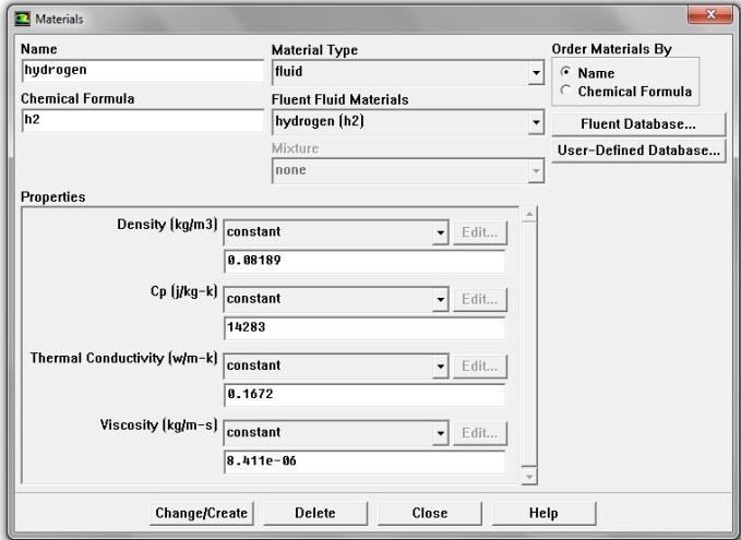
FluidcharacteristicsareloadedfromFluent'sdatalibrary.
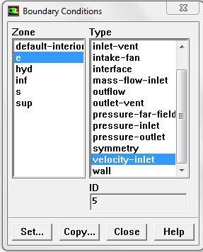
Fig -14 MaterialCharacteristics
Usual boundary conditions: DefineBoundaryConditions: Thevaluesoftheboundaryconditionsshallbefixedasfollows:
Fig -15 OperationBoundaryConditionsValues
International Research Journal of Engineering and Technology (IRJET) e-ISSN:2395-0056
Volume: 09 Issue: 12 | Dec 2022 www.irjet.net p-ISSN:2395-0072
International Research Journal of Engineering and Technology (IRJET) e-ISSN:2395-0056 Volume: 09 Issue:
International Research Journal of Engineering and Technology (IRJET) e-ISSN:2395-0056
Volume: 09 Issue: 12 | Dec 2022 www.irjet.net p-ISSN:2395-0072
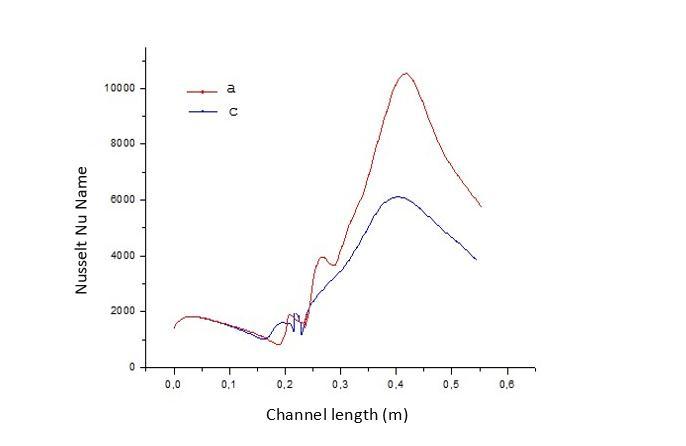
Fig -21 EffectoftheshapeofthebafflesontheNusseltnumberforcasesaandc. IV.10. Effect of the location and orientation of the angle of inclination
International Research Journal of Engineering and Technology (IRJET) e-ISSN:2395-0056
Volume: 09 Issue: 12 | Dec 2022 www.irjet.net p-ISSN:2395-0072
e. Orientationinthedirectionofflow
f. Orientationinthedirectionofflow
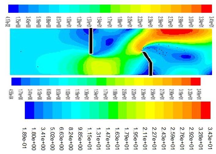
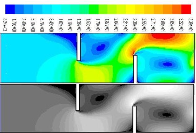
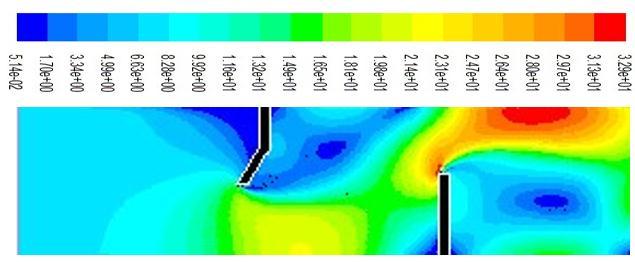
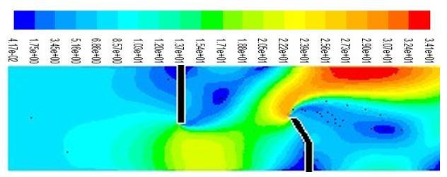
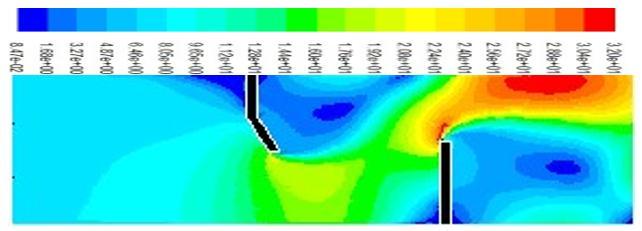
Fig -22 Velocityvectorsforcasesc,d,eandf
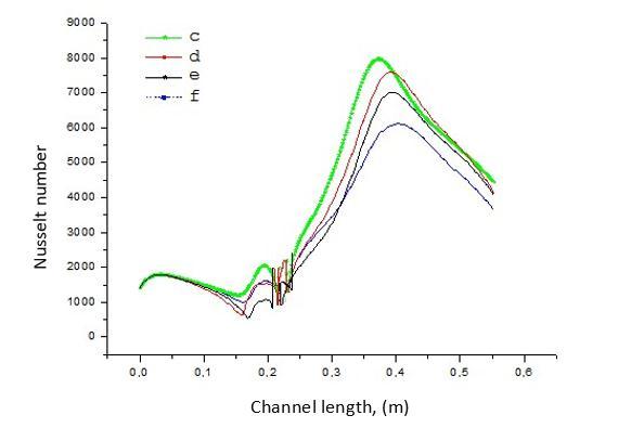
-23 EffectofthelocationandorientationoftheangleofinclinationontheNusseltnumberforcasesc,d,eandf
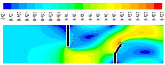
Fig-23showsthattheappearanceoftheNusseltvariationisidenticalinallcasesandthattheprofileisindependentofthe direction of orientation of the inclined part of the baffles, so the highest Nusselt number corresponds to case c, which allows us to conclude that the orientation effect of the baffles is effectively contributed to the improvement of heat exchangerates.
International Research Journal of Engineering and Technology (IRJET) e-ISSN:2395-0056
Volume: 09 Issue: 12 | Dec 2022 www.irjet.net p-ISSN:2395-0072
VI.11. Average Nusselt number: IV.11.1. Effect of the angle of inclination on the average Nusselt number
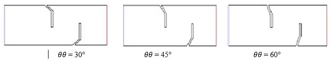
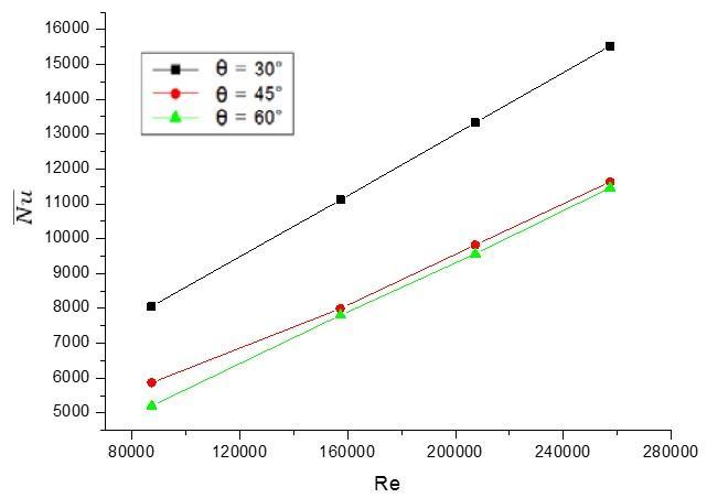
Fig -24 EffectoftheangleofinclinationθonthemeanNusseltnumberNNNN IV.11.2. Effect of the blocking factor on the average Nusselt number:
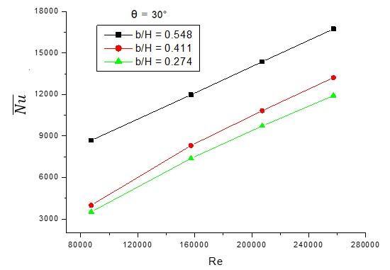
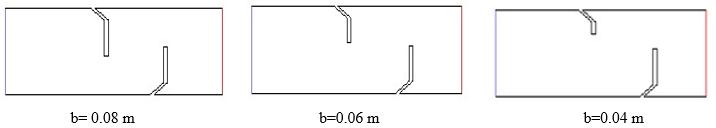
Fig -25 Effectofblockingfactorb/HonthemeanNusseltnumberNu
International Research Journal of Engineering and Technology (IRJET) e-ISSN:2395-0056
Volume: 09 Issue: 12 | Dec 2022 www.irjet.net p-ISSN:2395-0072
Fig -24 and 25 depict the variation of the mean Nusselt number NNNN as a function of the Reynolds number RRRR for variousvaluesofthedisruptor'sangleofinclinationandtheblockingfactorb/H.Thefiguresdemonstratethattheaverage NusseltnumberNNNNriseswithdecreasingdisruptorinclinationandrisingblockingfactorb/H.
Itisdeterminedthat the riseinthemean NusseltnumberNNNN valuesisonlycaused bychangesin thedisruptor'sand theblockingfactor'sinclinationangles.
Tables1and2,giveacomparisonbetweentheincreasedifferenceofNNNNasafunctionoftheangleofinclination θand theblockingfactorb/Hrespectively.
Table -1 NNNNincreasedeviationfordifferentvaluesofθ � 60°- 45° 60°- 30° ∆(%) 7,34 29,89
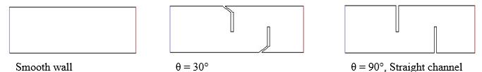
Table -2 NNNNincrementdeviationfordifferentb/Hvalues b/H 0,274-0,411 0,274-0,548 ∆(%) 8,60 40,32
IV.11.3. Effect of the channel form on the average Nusselt number
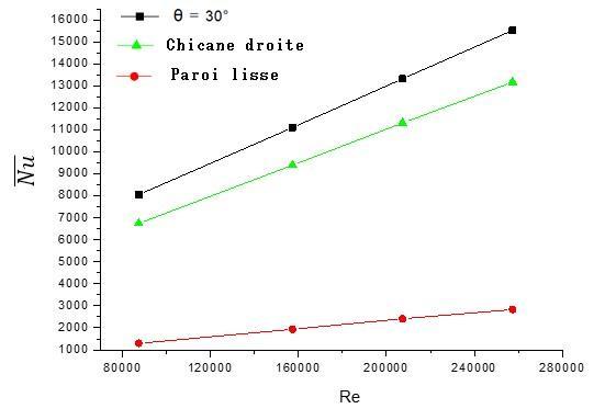
Fig -26 EffectofthechannelshapeonthemeanNusseltnumber
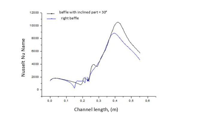
Fig-26,showstheeffectofthechannelshapeonthemeanNusseltnumberNaked,acomparisonwasmadebetweenthree different cases of the channel, the first is smooth, the other two have a straight channel θ = 90° and a channel has an inclinedpart θ= 30° respectivelynt,thecomparison resultsclearlystatethatthe channel effect with the inclined partis dominantthantheothercases,Table3
CaseA:Channelwithinclinedpartθ=30°-Withoutchannel(smoothwall)
CaseB:Straightchannelθ=90°-Withoutchannel(smoothwall)
International Research Journal of Engineering and Technology (IRJET) e-ISSN:2395-0056
CaseC:Channelwithinclinedpartofθ=30°-Straightchannelθ=90°
Table -3 DeviationfromNNNNelevationfordifferentchannelshapes case A B C ∆(%) 79,4 76,03 14,02
IV.11.4. Ratio of the average Nusselt number: IV.11.4.1. Effect of the angle of inclination on the ratio of the average Nusselt number:
Fig -27 EffectoftheangleofinclinationθontheratioofthemeanNusseltnumberNu⁄Nu0 IV.11.4.2. Effect of the blocking factor on the ratio of the average Nusselt number:
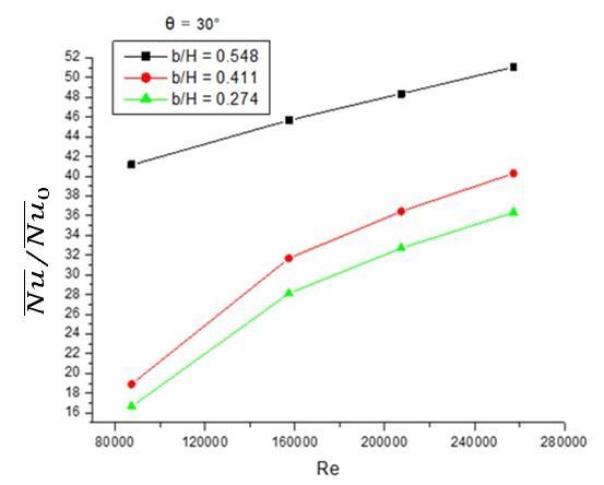
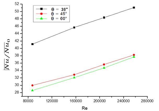
Fig -28 Effectofblockingfactorb/HontheratioofthemeanNusseltnumber NNNN⁄NNNN0
Volume: 09 Issue: 12 | Dec 2022 www.irjet.net p-ISSN:2395-0072 © 2022, IRJET | Impact Factor value: 7.529 | ISO 9001:2008 Certified Journal | Page704
International Research Journal of Engineering and Technology (IRJET) e-ISSN:2395-0056
Volume: 09 Issue: 12 | Dec 2022 www.irjet.net p-ISSN:2395-0072
Theeffectoftheblockingfactorb/HandtheinclinationruleθonthemeanNusseltratioNNNN⁄NNNN0 isshowninFig-27 and28.Accordingtothediagram,astheangleofinclinationisreduced,the ratiooftheaverageNusseltnumberrises,and astheblockingfactorvalueisreduced,theratiovaluesoftheaverageNusseltnumberdecline.
IV.11.5. Coefficient of friction:
IV.11.5.1. Effect of the angle of inclination on the coefficient of friction:
Fig -29 Effectoftheangleofinclinationθonthecoefficientoffrictionf⁄f0 IV.11.5.2. Effect of the blocking factor on the coefficient of friction:
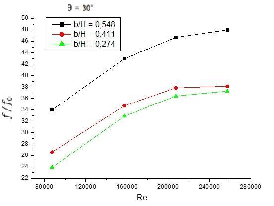
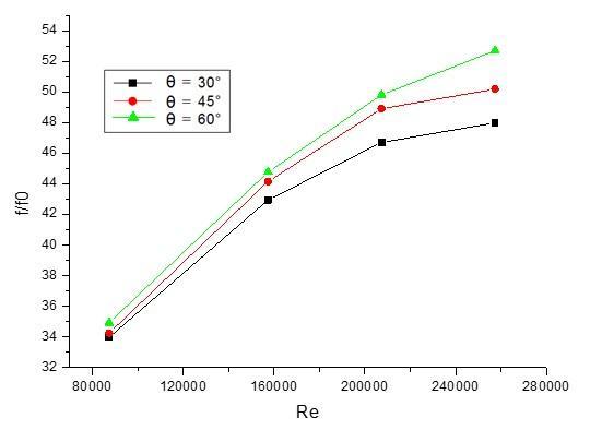
Fig -30 Influenceoftheblockingfactorbb/HHonthefrictioncoefficientff0
Forvariousvaluesoftheangleandtheblockingfactor bb/HH,thechangeofthecoefficientoffrictionff0asafunctionof the Reynolds number RRRR.is shown in Fig -29 and 30, it is noted that the fall in the coefficient of friction is displayed duringthedecreaseoftheangleofinclinationandthattheincreaseofthiscoefficientisaccomplishedbythegrowthof the blockfactorage.
International Research Journal of Engineering and Technology (IRJET) e-ISSN:2395-0056
Volume: 09 Issue: 12 | Dec 2022 www.irjet.net p-ISSN:2395-0072
IV.11.5.3. Effect of the channel shape on the coefficient of friction
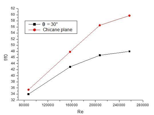
Fig -31 Effectofthechannelshapeonthecoefficientoffrictionf⁄f0
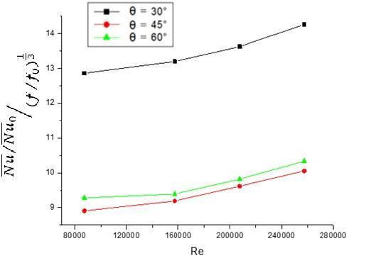
Fig -31, shows the results of comparison between two different cases of the channel shape, one is a flat channel θ = 90° andtheotherisachannelwithaninclinedpartθ=30°.Thecomparisonshowsthattherightchannelhasastrongeffecton thecoefficientof frictionff⁄ff0
IV.12. Thermal improvement factor
IV.12.1. Effect of the angle of inclination on the thermal improvement factor
Fig -32:Effectoftheangleofinclinationθonthethermalimprovementfactorηη
Thethermalimprovementfactorηη=NNNN⁄NNNN01isshowninFig-32,(��⁄��0)3 thisfactorincreaseswiththereduction oftheangleofinclination
International Research Journal of Engineering and Technology (IRJET) e-ISSN:2395-0056
Volume: 09 Issue: 12 | Dec 2022 www.irjet.net p-ISSN:2395-0072
IV.13. Average convective exchange coefficient: IV.13.1. Effect of the angle of inclination on the average convective exchange coefficient:
Fig - 33:Effectoftheangleofinclinationonthemeanconvectiveexchangecoefficienth IV.13.2. Effect of the blcage factor on the average convective exchange coefficient:
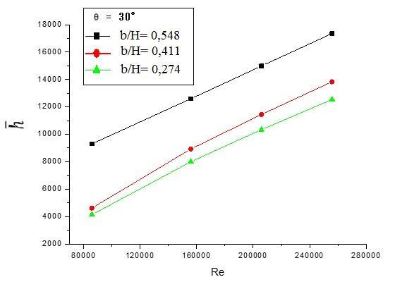
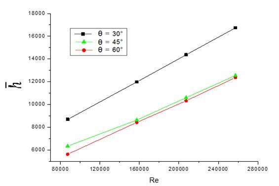
Fig –34 Effectofblockingfactorb/Honthemeanconvectiveexchangecoefficienth
Fig-33and34ShowhowtheaveragesurfaceexchangecoefficienthvarieswithrespecttotheReynoldsnumberwhenthe tilt angle and blocking factor are in play. As can be observed in Fig - 33, the small angles of inclination correlate to the maximum values of the mean convective heat transfer coefficient h. As the slopeis dropped, the intensity of the thermal exchange increases. The blocking factor, shown in Fig - IV, has a direct impact on the coefficient of heat transfer via averageconvection,orh.35demonstratesthatanincreaseintheaveragesurfaceexchangecoefficienth,oraround46.33 percent,isimpliedbyanincreaseinthechannels'height.
International Research Journal of Engineering and Technology (IRJET) e-ISSN:2395-0056
Volume: 09 Issue: 12 | Dec 2022 www.irjet.net p-ISSN:2395-0072
Conclusion-
The k-numerical model's findings are validated and given in order to evaluate the influence of geometry on the performanceofheatexchangersforturbulentfluidflowinforcedconvectioninarectangularchannelwithangledbaffles. Theinstabilityofheatexchangesthroughoutthechannelisgreatlyimpactedbytheexistenceofrecirculationzones,which are generated when baffles are present. Negative and positive values of velocities, indicated as an abrupt shift in flow direction, are characteristic of the profile fluctuation of velocities caused by these recirculation zones. Heat transfer efficiency is maximised when the channel’s inclined section has a shallow angle of inclination, and the channel’s orientationhasasignificantimpactonhowquicklyheatistransferred.
1. Pethkool S, Kwankaomeng, S, Promvonge P. Turbulent heat transfer enhancement in heat exchange using helically corrugatedtube.IntCommunicationsHeatMassTransfer,2011;38:340–347.
2. PromvongeP.Heattransferandpressuredropinachannelwithmultiple60°V-Baffles.InternationalCommunications inHeatandMassTransfer,2010;37:335-840.
3. Demartini L. C, Vielmo H. A, Moller S.V . Numeric and experimental analysis of the turbulent flow through a channel withbaffleplates.JournaloftheBrazilianSocietyofMechanicalSciencesandEngineering,2004;26(2):153-159.
4. Bensenouci D, Aliane K, Sari-Hassoun Z. Thermal study of forced convection in a rectangular pipeequipped with baffles,2ndInternationalConferenceofRenewableEnergiesCIER-2014.InternationalJournalofScientificResearch& EngineeringTechnology(IJSET),2015;3:123-127.
5. Menni Y, Azzi A, Zidani C. Comparative numerical study between two types of baffles and fins, rectangular and rounded rectangular,usedtoimprovetheperformance offlatairsolarcollectors,RenewableEnergies,2015;18(3): 347–361.
6. Tsay Y L, Chang T S, Cheng J C. Heat transfer enhancement of backward-facing step flow in a channel byusing baffle installedonthechannelwall,ActaMech,.2005;174:63–76.
7. Bilen K, Cetin M, Gul H, Balta T. The investigation of groove geometry effect on heat transfer for internally grooved tubes.AppliedThermalEngineering,2009;29(4):761–769.
8. NasiruddinM.H.SiddiquiK.Heattransferaugmentationinaheatexchangertubeusingabaffle.InternationalJournal ofHeatandFluidFlow,2007;28:318–328.
9. J. Li, S. Wang, J. Chen. Numerical study on a slit fin and tube heat exchanger with longitudinal vortex generators Internationaljournalofheatandmastransfer,2011;54:1743-1751.
10. Wang Y,LiuZ, Huang S.Experimental investigationofshell andtube heat exchangerwitha newtypeof baffles, heat masstransfer,2011;47:833-839.