International Research Journal of Engineering and Technology (IRJET) e-ISSN: 2395-0056

Volume: 09 Issue: 12 | Dec 2022 www.irjet.net p-ISSN: 2395-0072
International Research Journal of Engineering and Technology (IRJET) e-ISSN: 2395-0056
Volume: 09 Issue: 12 | Dec 2022 www.irjet.net p-ISSN: 2395-0072
1Post Graduate Student, Dept. of Civil Engineering, Datta Meghe College of Engineering Airoli, Navi Mumbai- 400708, India
2Professor and Head, Dept. of Civil Engineering, Datta Meghe College of Engineering Airoli, Navi Mumbai- 400708, India
3Professor, Dept. of Civil Engineering, Datta Meghe College of Engineering Airoli, Navi Mumbai- 400708, India ***
Abstract - Bridges are the structures which are built to maintain the communication between two places which are separated by any obstacle like river, valley, road, railway in the form of crossing roadway or railway. To attend the optimum and economical solution, the bridge built on any crossing shall be perpendicular one, which results in optimized span and restrained length of piercap. Skew bridges are needs to be introduced in the highways or bridges to keep the alignment of roadways as straight as possible which ultimately results in smooth and speedy traffic, subsequently economy in commuting. The current investigation is carried out to analyze and study the behavior of skewed bridges and mainly to understand the effect of skewness of bridge on the intermediate diaphragms. The effect of skewness on main girders and on intermediate diaphragms studied and presented. Also, two different configurations for intermediate diaphragm are proposed and its overall behavior studied. In continuation, the effect of intermediate diaphragm on girders is studied and results were compared and presented
KeyWords: SkewedDeckSlabBridge,Skewness,IntermediateDiaphragms,Girders,CrossDiaphragms
Skewed bridges are necessary to cross roadways, waterways or any obstacle with an angle other than 90 degrees. In general,theskewedangleisdefinedastheanglebetweenthelinenormaltothecenterlineofbridgeoralignmentandthe centerlineofsupport(abutmentorpier).Theskewedanglelessthan20degreesalmoststimulatesalmostsimilarbehavioras thatofstraightbridge.But,astheanglestartsincreasingfurther,thebehaviorandforcedistributionstartschangingasthatof straightspan.Theintermediateandenddiaphragmsplayanimportantpartintheloaddistributionamongthegirdersandthe introductionofskewnessinthebridgechangestheloaddistributioncompletely.
Theintermediatediaphragmisthememberthatconnectstwoparallelrunningmembersusedforresistinglateralforces resultingin transfer of loadsto the pointsofconnection.Intermediate diaphragmsarea majorcontributorto theoverall distributionofloads,particularlyliveloadsinbridges.Almostallthebridgesconstructedhaveintermediatediaphragms,which aremostly continuousorsimplysupported.Continuous diaphragmsprovidecontinuity inforcetransfer,whereassimply supporteddiaphragmactsasabeambetweentwoadjacentparallelgirders.Constructionofintermediatediaphragmsismostly asiteactivity.Insteelorsteel-compositebridges,theyareboltedorweldedwiththemaingirdersandinthecaseofRCCorprestressedbridges,theyarecastintegrallywiththedeckslabbyprovidingappropriatereinforcement.
In the construction of skewed bridges, one of the major issues of arranging and placing the end and intermediate diaphragms,sincetheintermediatediaphragmsareconnectingatdifferentpointsofthegirder,thereisdifferenceindeflection ofgirders,whichproducessecondarystressesinthegirders.Astheskewnessofbridgegoesonincreasing,theimpactof intermediatediaphragmsongirdersalsogoesonincreasing.Also,aspertheconfiguration,thebehaviorandforcetransfer withinintermediatediaphragmsalsochanges,soastheforcesinintermediatediaphragms.
Astheintermediatediaphragmsonlydistributesalltheloadsamongthegirders,it’sarrangementwithrespecttogirders plays an important role. The main objective is to analyze the skewed deck slab bridge for different configuration of intermediate diaphragm to identify the effect of intermediate diaphragms on main girders. Also, to evaluate the effect of skewnessonintermediatediaphragmswithdifferentconfigurationascomparedtostraightspanofthebridge Incontinuation, tofindthesolutiontominimizetheeffectofskewnessongirdersandintermediatediaphragms,sothatoptimumdesigncanbe presented.
International Research Journal of Engineering and Technology (IRJET) e-ISSN: 2395-0056
Volume: 09 Issue: 12 | Dec 2022 www.irjet.net p-ISSN: 2395-0072
Tillnowmultiplestudiesarecarriedoutontheanalysisofskeweddeskslabbridgesandloaddistributionfactorsinskewed bridges.Fewliteraturesarealsoavailableonhowintermediatediaphragmscontributeinoverallbehaviorofdeckslabbridges. AliKhalooandMirzabozorg(2003)[7]analyzedsimplysupportedbridgesconsistingoffiveI-sectionconcretegirdersbyfinite elementmethodandcarriedouttheparametricstudytoworkouttheloaddistributionfactors.OguzC.Celik&MichelBruneau (2011)[4]addressedtheissueofimplementingtheductilediaphragmsinskewedbridgeswhichareintroducedbytheAASHTO guidespecificationsasastructuralsystemthatcanbeusedtoresisttransverseearthquakeeffects.Itwasobservedthat,the baseshearstrengthandlateralstiffnessofenddiaphragmdecreases&driftincreasesastheskewangleincreases.JawadGull, AtorodAzizinamini&ToddHelwig(2017)[2]workedonthestructuralresponsesprovidedbythedifferentdetailingmethods fortheskewedsteelIgirderbridgesalongwithintermediatediaphragms.JenniferMcConnell,MatijaRadovic&KellyAmbrose (2016)[3]carriedoutthefieldtesttounderstandtherelationshipamonggirderstresses,cross-framedesignandskewangleof twosteelI-girderbridges,whichhavemoderateandhighlevelsofskewanddifferingcross-framedesigns.WalterDilger,Gamal Ghoneim&GamilTadros(1988)[10]carriedoutthestudytoidentifytheeffectofdiaphragmsonthereactions,internalforces, andbehaviorofskewboxgirderbridgesforskewdiaphragms,orthogonaldiaphragmsandnodiaphragmscondition.
Inthecurrentstudy,atypical50mdeckslabbridgewithskewedangleof60degreeswasconsideredfortheanalytical investigation. Table 1 shows the properties of material which are used in the analysis. Table 2 and 3 shows the sectional propertiesofmembersanddimensionalparametersofgeometry,respectively.
ConcreteGradeM50
ReinforcementSteelGradeFE500 StructuralSteelGradeE350
Main Girder Properties
TopFlange: 700mmx32mm
BottomFlange: 900mmx40mm Web: 2650mmx25mm OverallHeight: 2722mm
ConcreteDensity=25KN/m3 SteelDensity=77KN/m3
Intermediate Diaphragm Properties: “X bracing is used”
Topchord: 2ISA-150x150x10
Bottomchord: 2ISA-150x150x10 Inclinedchords: 2ISA-150x150x10
TopFlange: 500mmx20mm
BottomFlange: 600mmx25mm Web: 2000mmx16mm OverallHeight: 2045mm
Component of Bridge Section Dimension (Length/Width/Depth)
WidthofEachCarriageway
WidthofMedian
WidthofAnti-CrashBarrier
OverallCarriagewayWidth C/cspacingbetweenthegirders Cantileverspanatbothends ThicknessofDeck-Slab
Thicknessofwearingcoat
Drainageslope
7.50m(2Lanes) 1.20m 0.50m 7.50x2+1.20+0.50x2=17.20m 2.80m(typical) 1.60m(transversely) 0.25m 0.09m 2.50%
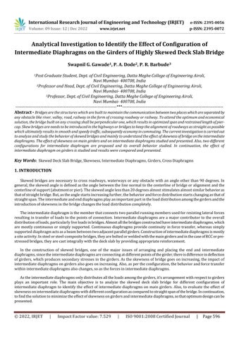
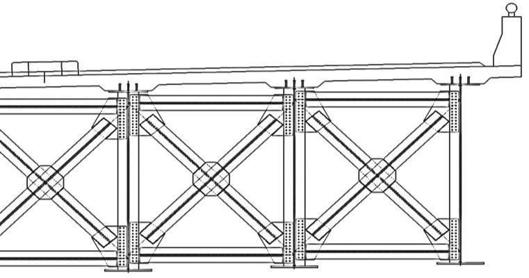
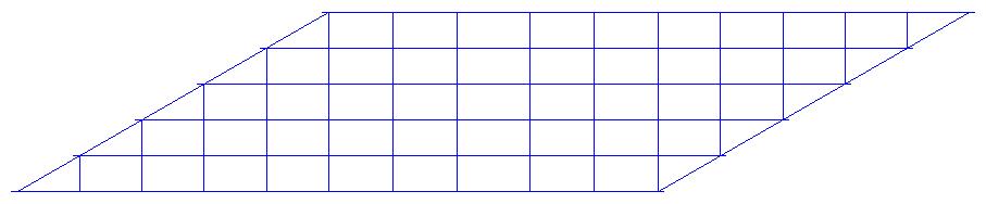
Theactualcross-sectionofbridgeisshowninFig.1whereas,Fig 2,4and5showsthelinediagramofbridgemodelinplan Fortheanalysispurpose,MidasCivil softwareisused.For comparisonandinitialunderstandingofforcesandbehavior,a standard50mstraightmodel(withskewangle0degrees)ispreparedandplanviewofthesameisshowninFig.2.
International Research Journal of Engineering and Technology (IRJET) e-ISSN: 2395-0056
Enddiaphragms (typ.)
Fig -1: Cross-sectionofBridge
G6 G5 G4 G3 G2 G1
Fig -2: Planof50m
Girders(typ.)
Intermediate diaphragms(typ.)
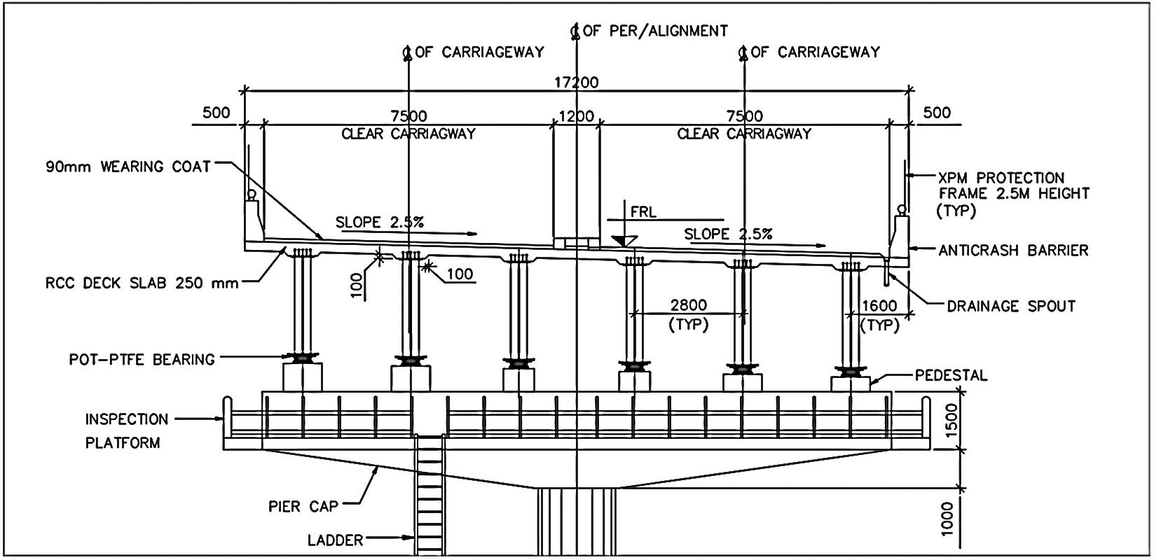
Theintermediatediaphragmarrangementisshownin Fig.3.Theyareconnectedtotwoadjacentgirderswithbolting arrangementandareatdifferentelevationstomaintainthetransverseslopeofdrainageinonedirection.
Girders(typ.)
Intermediate diaphragms(typ.)

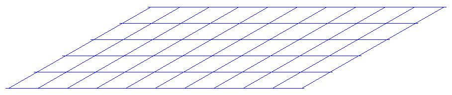
Twodifferentconfigurationsofintermediatediaphragmsareproposedtofulfilltheprimeobjectiveoftheresearch.Fig.4 andFig.5showsplanviewoftheskewedbridgespanwithtwodifferentarrangementsofintermediatediaphragms.These modelsarefurtherusedforforcecomparisonandinterpretationofresults.
Volume: 09 Issue: 12 | Dec 2022 www.irjet.net p-ISSN: 2395-0072 © 2022, IRJET | Impact Factor value: 7.529 | ISO 9001:2008 Certified Journal | Page598
International Research Journal of Engineering and Technology (IRJET) e-ISSN: 2395-0056
Volume: 09 Issue: 12 | Dec 2022 www.irjet.net p-ISSN: 2395-0072
Intermediate diaphragms(typ.)
Intermediate diaphragms(typ.)
Fig -4: Configuration1ofIntermediateDiaphragmforSkewedSpan
Girders(typ.)
Girders(typ.) G6 G5 G4 G3 G2 G1 G6 G5 G4 G3 G2 G1
Fig -5: Configuration2ofIntermediateDiaphragmforSkewedSpan
Thetypicalsetofloadingsconsideredisasfollows:
Enddiaphragms (typ.)
Enddiaphragms (typ.)
[1] Self-weightofthegirders: Theself-weightofgirdersisconsideredwiththehelpof“SELF-WEIGHT”commandofthesoftware. Factorof1.20isconsideredtoaccounttheothermiscellaneousfixtures/loads.
[2] DeckSlab: 250mmthk.deckslabwithdensityofconcreteas25kN/m3 Areaload = 0.25x25 = 6.25kN/m2
[3] WearingCoat: 90mmthk.wearingcoatwithdensityas22kN/m3 Areaload = 0.09x22 = 1.98kN/m2
[4] CrashBarrier:
AreaofCBisapproximatelyaround0.50m2 withdensityas25kN/m3 Uniformload = 0.50x25 = 12.50kN/m Thisuniformlydistributedloadappliedontheperipheralgirdersofthesystem.
[5] Median: Medianisapproximately0.50mindepthand1.20mwidewithdensityas25kN/m3 Areaload = 0.50x25 = 12.50kN/m2 Thisuniformlydistributedloadappliedonthecentraltwogirdersofthesystem.
2022, IRJET | Impact Factor value: 7.529 | ISO 9001:2008 Certified
International Research Journal of Engineering and Technology (IRJET) e-ISSN: 2395-0056
Volume: 09 Issue: 12 | Dec 2022 www.irjet.net p-ISSN: 2395-0072
[6] LiveLoads:
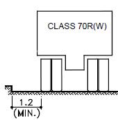
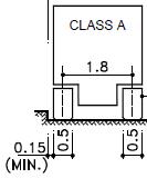
LiveloadsareconsideredaspercodeIRC:6-2017(StandardSpecificationsandCodeofPracticeForRoadBridges). Importantly,vehiclesClassAandClass70R(wheeled)areconsideredfortheliveloadcombinations. LiveloadcombinationsprimarilyaresingleClassAvehicle,twoClassAvehicleandsingleClass70Rvehiclein eachlane.Fortheanalysisofboththelanes,combinationofvehiclesineachlaneareconsideredandcriticalor noteworthyloadcombinationisidentifiedfortheforceextractionandfurthercomparison.
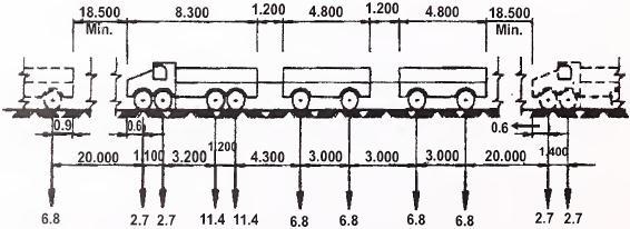
Fig -6: ClassATrainofVehicles (Loadvaluesarein‘Ton’&Dimensionsarein‘m’)
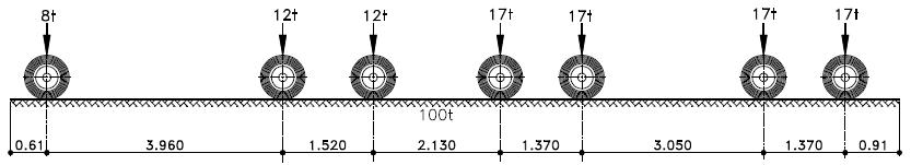
Fig -7: Class70RTrainofVehicles (Loadvaluesarein‘Ton’&Dimensionsarein‘m’)
Theboundaryorsupportsaretheone,wheregenerallygirderrestsonthepier-caporabutment.Oftensupportsareinthe formofdifferenttypeofbearinglikeelastomericbearing,POT-PTFEbearing,neoprenebearingandsoon.Thesebearings providetranslationalorrotationalmovementdependingonthedesignrequirementsanditalsoaffectstheoverallbehaviorof thestructure,speciallythesub-structure.
Theboundaryconditionsforthegirdersareconsideredasshowninfig.8 Itshowsforthe50mstraightspanandsame conditionsarefurtherusedforskewedspanalsoforboththeconfigurationswith60degreesskewedangle.
TransverselyGuided
TransverselyGuided Fixed Fixed
TransverselyGuided
TransverseDirection
LongitudinalDirection
Fig -8: PlanShowingBoundaryConditionsConsideredForTheGirders
International Research Journal of Engineering and Technology (IRJET) e-ISSN: 2395-0056
Volume: 09 Issue: 12 | Dec 2022 www.irjet.net p-ISSN: 2395-0072
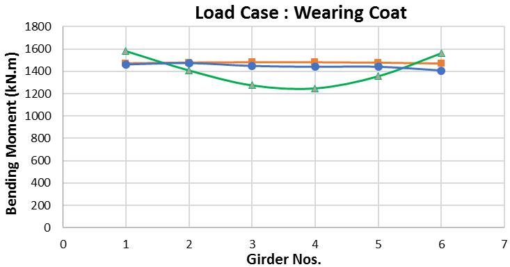
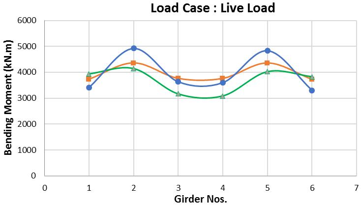
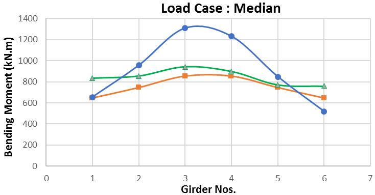
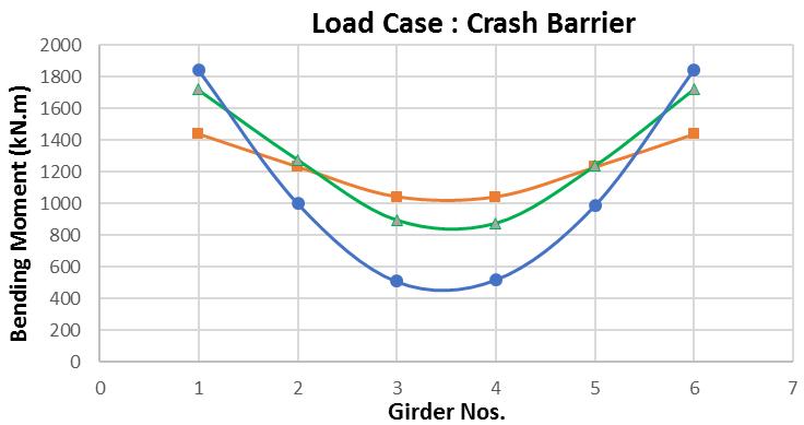
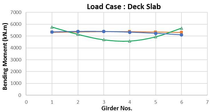
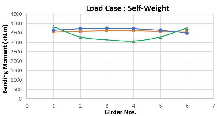
FollowingarethegraphsofbendingmomentdiagramsplottedforthegirdersG1toG6forvariousloadcaseswith straightspan,intermediatediaphragmconfiguration1andintermediatediaphragmconfiguration2.
(a) (b) (c) (d) (e) (f)
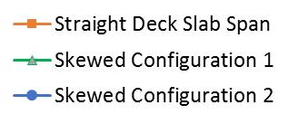
Legend:
Chart -1: BendingMomentDiagramsforVariousLoadCases(kN.m)
2022, IRJET | Impact Factor value: 7.529 | ISO 9001:2008 Certified Journal |
International Research Journal of Engineering and Technology (IRJET) e-ISSN: 2395-0056
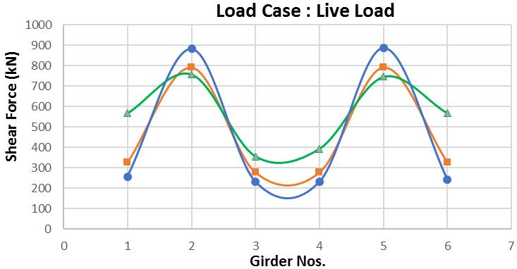
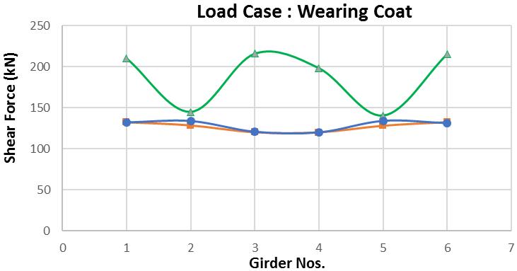
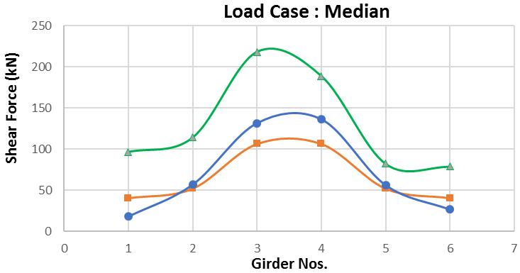
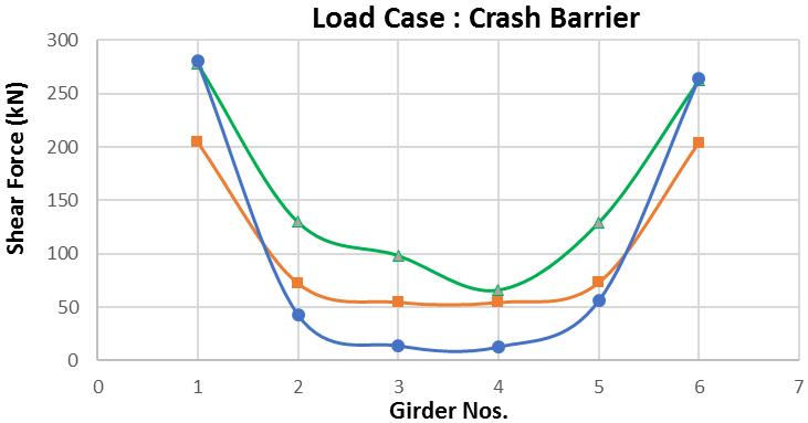
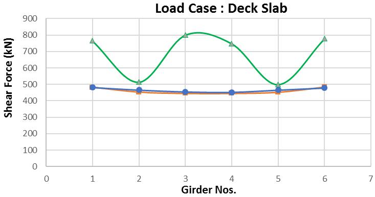
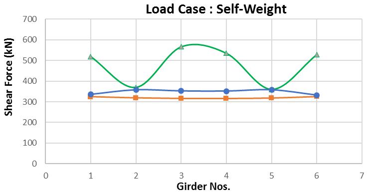
FollowingarethegraphsofshearforcediagramsplottedforthegirdersG1toG6forvariousloadcaseswithstraight span,intermediatediaphragmconfiguration1andintermediatediaphragmconfiguration2
(a) (b) (c) (d)
(e) (f)
Legend:
Chart -2: ShearForceDiagramsforVariousLoadCases(kN)
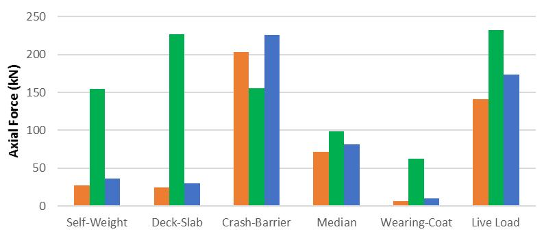
Followingisthechartshowingcomparisonofaxialforcesdevelopedintheintermediatediaphragmsforvariousload caseswithstraightspan,intermediatediaphragmconfiguration1andintermediatediaphragmconfiguration2
Volume: 09 Issue: 12 | Dec 2022 www.irjet.net p-ISSN: 2395-0072 © 2022, IRJET | Impact Factor value: 7.529 | ISO 9001:2008 Certified Journal | Page602
International Research Journal of Engineering and Technology (IRJET) e-ISSN: 2395-0056
Volume: 09 Issue: 12 | Dec 2022 www.irjet.net p-ISSN: 2395-0072
Thestraightmodelofspan50mispreparedwithloadingsasmentionedinsection4.Incontinuation,respectiveskewed modelsarepreparedwith60degreesofskewness.Twodifferentconfigurationsforintermediatediaphragmsareproposedand theforcecomparisonisdoneandpresentedforthegirdersandintermediatediaphragmsinsection5.0
The comparison of bending moments generated in girders G1 to G6 for straight span, 1st skewed and 2nd skewed configurationisplottedinChart-1forindividualloadcases.Fromthesecomparativegraphs,itcanbeobservedthat,
a. Fortheloadcase Self-Weight,thebendingmomentvaluesobtainedforstraightspanandwith2ndskewedconfigurationare almostidenticalinbehaviorandsameinvalues.Thereisasignificantdifferenceinvaluesandbehaviorofbendingmoments obtained with 1st skewed configuration. The bending moment values are in the range of 3520 kN.m to 3750 kN.m for straightspanand2ndskewedconfiguration,whilevariationofbendingmomentismorefor1stskewedconfigurationranging from3000kN.mto3750kN.m.
b. Fortheloadcase Deck Slab,thevaluesofbendingmomentsaredifferentasthatofloadcaseSelf-Weightbut,thebehaviorof resultsareinlinei.e.resultsofstraightspanandtheoneobtainedwith2nd skewedconfigurationaresame.Thebending momentvaluesareintherangeof5500kN.mforstraightspanand2nd skewedconfiguration,whilevariationofbending momentismorefor1st skewedconfigurationrangingfrom4500kN.mto5750kN.m.
c. Fortheloadcase Crash Barrier,theperipheraltwogirdersgetmoreinfluenced,asthelocationcrashbarrierisattheedges. Thesegirdersmajorlyconsideredforthecomparison.Itcanbeseenthat,allthethreeconditionsbehavedifferentlyunder thisloadingandgivesdifferentbehavior.Thebendingmomentgeneratedforstraightspanisaround1400kN.m,for1st skewedconfigurationisaround1700kN.mwhereasfor2nd configurationitisaround1850kN.m.
d. Fortheloadcase Median,thecentraltwogirdersgetmoreinfluenced,asthelocationofmedianisatthecenterofthebridge. Thesegirdersmajorlyconsideredforthecomparison.Itcanbeseenthat,allthethreeconditionsbehavedifferentlyunder thisloadingandgivesdifferentbehavior.Thebendingmomentgeneratedforstraightspanisaround850kN.m,for1st skewedconfigurationis950kN.mwhereasfor2nd configurationitisaround1300kN.m.
e. Fortheloadcase Wearing Coat,thevaluesofbendingmomentsaredifferentasthatofloadcaseDeckSlabbut,thebehavior ofresultsareinlinei.e.resultsofstraightspanandtheoneobtainedwith2ndskewedconfigurationaresame.Thebending momentvaluesareintherangeof1400kN.mto1500kN.mforstraightspanand2ndskewedconfiguration,whilevariation ofbendingmomentismorefor1st skewedconfigurationrangingfrom1250kN.mto1600kN.m.
f. Fortheloadcase Live Load,thecombinationofvehicle70Rineachlaneiscriticalandshowstheappropriateresults.The bendingmomentgeneratedforstraightspanisaround3750kN.mto4500kN.mandfor1stskewedconfigurationitis3000 kN.mto4000kN.mwhereasfor2ndconfigurationitisaround3500kN.mto5000kN.m.Thoughresultsarenotsimilarwith eachother,behaviorisidenticalinallthecasesandthepointtobenotedhereisthat,thevariationinvaluesofbending momentismuchhigherinthecaseof2nd skewedconfiguration.
International Research Journal of Engineering and Technology (IRJET) e-ISSN: 2395-0056
Volume: 09 Issue: 12 | Dec 2022 www.irjet.net p-ISSN: 2395-0072
Followingtothecomparisonofbendingmoment,maximumshearforces,inotherwords,reactionvalues generatedin girdersG1toG6forstraightspan,1stskewedand2ndskewedconfigurationisplottedinChart-2forindividualloadcases From thesecomparativegraphs,itcanbeobservedthat,
a. Fortheloadcase Self-Weight,theshearforcevaluesobtainedforstraightspanandwith2ndskewedconfigurationarealmost identical inbehavior.There isa significantdifferencein valuesandbehaviorofshearforcesobtained with1st skewed configuration.Theshearforcevaluesareintherangeof320kNto360kNforstraightspanand2nd skewedconfiguration, whilevariationofshearforceismorefor1st skewedconfigurationrangingfrom360kNto550kN.
b. Fortheloadcase Deck Slab,thevaluesofshearforcesaredifferentasthatofloadcaseSelf-Weightbut,thebehaviorof resultsareinlinei.e.resultsofstraightspanandtheoneobtainedwith2ndskewedconfigurationaresame.Theshearforce valuesareintherangeof450kNto475kNforstraightspanand2ndskewedconfiguration,whilevariationofshearforceis morefor1st skewedconfigurationrangingfrom500kNto800kN.
c. Fortheloadcase Crash Barrier,theperipheraltwogirdersgetmoreinfluenced,asthelocationcrashbarrierisattheedges. These girders majorly considered for the comparison. They behave differently under the three conditions and gives differentbehavior.Theshearforcegeneratedforstraightspanisaround210kN,for1stskewedconfigurationisaround270 kNwhereasfor2nd configurationitisaround275kN.
d. Fortheloadcase Median,thecentraltwogirdersgetmoreinfluenced,asthelocationofmedianisatthecenterofthebridge. These girders majorly considered for the comparison. They behave differently under the three conditions and gives differentbehavior.Theshearforcegeneratedforstraightspanisaround120kN,for1st skewedconfigurationis200kN whereasfor2nd configurationitisaround130kN.
e. Fortheloadcase Wearing Coat,thevalueofshearforcesisdifferentasthatofloadcaseDeckSlabbut,thebehaviorof resultsisinlinei.e.resultsofstraightspanandtheoneobtainedwith2nd skewedconfigurationaresame.Theshearforce valuesareintherangeof120kNto140kNforstraightspanand2ndskewedconfiguration,whilevariationofshearforceis morefor1st skewedconfigurationrangingfrom140kNto220kN.
f. Fortheloadcase Live Load,thecombinationofvehicle70Rineachlaneiscriticalandshowstheappropriateresults.The shearforcegeneratedforstraightspanisaround300kNto800kNandfor1stskewedconfigurationitis350kNto750kN whereasfor2nd configurationitisaround220kNto900kN.Thoughresultsarenotsimilarwitheachother,behavioris identicalinallthecasesandthepointtobenotedhereisthat,thevariationinvaluesofbendingmomentismuchhigherin thecaseof2nd skewedconfigurationascomparedwithothertwo.
As we have seen, how different configurations of intermediate diaphragm impacts the overall behavior of girder and variationindesignforceslikebendingmoments,shearforces,etc.,theintermediatediaphragmalsobehavesdifferentlyunder differentconfigurations.Astheintermediatediaphragmsareprimarilyaxialforcecarryingmembers,theaxialforcesdeveloped underallthe3conditionsareplottedinChart-3forindividualloadcases.Itcanbeseenthat,
a. Fortheloadcase Self-Weight,theaxialforcesdevelopedinintermediatediaphragmsareidenticalinstraightspanand2nd skewedconfigurationandarearound25kNto30kN.1st configurationgivesverymuchhighvaluearound155kN.
b. Fortheloadcase Deck Slab,theaxialforcesdevelopedinintermediatediaphragmsareidenticalinstraightspanand2nd skewedconfigurationandarearound25kNto30kN.1st configurationgivesverymuchhighvaluearound225kN.
c. Fortheloadcase Crash Barrier,theaxialforcesdevelopedinintermediatediaphragmsareidenticalinstraightspanand2nd skewedconfigurationandarearound200kNto225kN.1st configurationgivescomparativelylowvaluearound150kN.
d. For the load case Median, the axial forces developed in intermediate diaphragm are almost identical under all the 3 conditionsandvaluevariesfrom75kNto100kN.
e. Fortheloadcase Wearing Coat,theaxialforcesdevelopedinintermediatediaphragmsareidenticalinstraightspanand2nd skewedconfigurationandarearound10kN.1st configurationgivescomparativelyhighvalueof60kNascomparedwith othertwo.
International Research Journal of Engineering and Technology (IRJET) e-ISSN: 2395-0056
Volume: 09 Issue: 12 | Dec 2022 www.irjet.net p-ISSN: 2395-0072
f. Fortheloadcase Live Load,thecombinationofvehicle70Rineachlaneiscriticalandshowstheappropriateresults.The axialforceforstraightspanisaround140kNandfor1stskewedconfiguration,itis235kNwhereasfor2ndconfigurationit is around 175 kN. The point to be noted here is that, the value of axial force is much higher in the case of 1st skewed configurationascomparedwithothertwo.
A 50m straight span grillage model was prepared and 60 degrees skewed model with two different intermediate configurations were prepared. These are then analyzed and major design forces like bending moments, shear forces are comparedandplottedfor6differentloadcases.Thebehaviorpatternofgirderswithrespecttotheseproposed2different configurationsofintermediatediaphragmswerestudied.Also,theaxialforcesinintermediatediaphragmareobservedand compared.Followingconclusionsaremadefromtheobservations.
1. The1stskewedconfigurationresultsinunevendistributionofforcesandgivesreducedeconomyinthegirders.There ismoredifferenceindesignvalueswhenitiscomparedwithstandardstraightspancondition.Thereasonforthisis,in this configuration, the intermediate diaphragm connects the two dissimilar deflection point of girders. But, the constructionwiththisconfigurationiseasyandmorefeasible.
2. The2ndskewedconfigurationresultsinevendistributionofforcesandmostoptimizeddesignofthegirders.Thevalue ofdesignforcesandbehaviorofgirdersarealmostinlinewiththestandardstraightspancondition.Thereasonfor thisis,inthisconfiguration,theintermediatediaphragmconnectsthetwosimilardeflection pointofgirders,very similarwithstraightspancondition.But,theconstructionwiththisconfigurationisdifficultandmoretimeconsuming.
3. Itcanbeconcludedthat,theconfigurationofintermediatediaphragmsplaysanimportantroleindistributionofforces anditmajorlycontrolthedesignforcesdevelopedinthegirders.Theproperselectionofconfigurationofintermediate diaphragmscanleadtoevendistributionofforces,resultinginoptimizeddesignofgirders.
4. Theaxialforcesgeneratingintheintermediatediaphragmcanalsobecontrolledbychoosingtheproperconfiguration. While1st skewedconfigurationattractsmoreforces,2nd skewedconfigurationgivesalmostsameresultsasthatof straightspan
5. Theproperpre-camberingisalsothesolutiontoreducethedifferentialdeflectionofgirdersatthetwodiaphragm connectingpoints,whichcanalsoleadtoproperdistributionofforces.Cambershallbeprovidedforalltheloadcases exceptliveloadtoachievethefulladvantage.Thiswillworkbygenerationoflessaxialforcesindiaphragm,asitis happeninginthecaseofstraightor2nd skewedconfiguration.
[1] FaressHraib,LiHui,Miguel VicenteandRiyadhHindi,“DiaphragmOrientationEffectontheRotationofExterior GirdersduringConstructioninSkewedBridges”57-67,StructuresCongress2019
[2] JawadGull,AtorodAzizinamini&ToddHelwig,“ComparisonofdetailingmethodsforstraightskewedsteelI-girder bridges”JournalofConstructionalSteelResearch,136,24–34,2017
[3] JenniferMcConnell,MatijaRadovic&KellyAmbrose,“FieldEvaluationofCross-FrameandGirderLive-LoadResponse inSkewedSteelI-GirderBridges”JournalofBridgeEngineering,1604015062,No.21(3),2016
[4] OguzCelik&MichelBruneau,“SkewedSlab-on-GirderSteelBridgeSuper-structureswithBidirectional-DuctileEnd Diaphragms”JournalofBridgeEngineering,Vol.16,No.2,207-218,2011
[5] AzizSaberandWalidAlaywan,“Full-ScaleTestofContinuityDiaphragmsinSkewedConcreteBridgeGirders”Journal ofBridgeEngineering,21-28,Vol.16,No.1,January1,2011
[6] Haoxiong Huang, Harry Shenton & Michael Chajes, “Load Distribution for a Highly Skewed Bridge: Testing and Analysis”JournalofBridgeEngineering,Vol.9,No.6,558-562,2004
[7] AliR.Khaloo& H. Mirzabozorg, “LoadDistributionFactorsinSimplySupported Skew Bridges” Journal ofBridge Engineering,Vol.8,No.4,241-244,2003
[8] S.Kimbara,S.Shimizu,“Elasto-plasticLargeDeflectionAnalysisofEndSupportDiaphragmsinSkewSteelBoxGirders” J.Construct.SteelResearch,173-190,32,1995
[9] AlfredBishara,Maria Chuan Liu&NasserD.El-Ali,“Wheel LoadDistribution On SimplySupported SkewI-Beam CompositeBridges”JournalofStructuralEngineering,Vol.119,No.2,399-419,1993
[10]WalterDilger,GamalGhoneim&GamilTadro,“Diaphragmsinskewboxgirderbridges”869-878,Can.J.Civ.Eng.15, (1988)
[11]IRC:6-2017“StandardSpecificationsandCodeofPracticeForRoadBridges”;SectionII:LoadsandLoadCombinations
International Research Journal of Engineering and Technology (IRJET) e-ISSN: 2395-0056 Volume: 09 Issue: 12 | Dec 2022 www.irjet.net p-ISSN: 2395-0072 © 2022, IRJET | Impact Factor value: 7.529 | ISO 9001:2008 Certified Journal |