International Research Journal of Engineering and Technology (IRJET) e-ISSN: 2395-0056

Volume: 09 Issue: 12 | Dec 2022 www.irjet.net p-ISSN: 2395-0072
International Research Journal of Engineering and Technology (IRJET) e-ISSN: 2395-0056
Volume: 09 Issue: 12 | Dec 2022 www.irjet.net p-ISSN: 2395-0072
1Dept. of Electrical and Electronics Engineering, SSTC Bhilai, CG, India ***
Abstract: - It is suggested to use a multiple input boost converterwithhighvoltagegain.Thephotovoltaicusesfor this converter are possible. This converter allows the simultaneous extraction of continuous current from multiple sources. The converter's steady state analysis is presented. To take in the most electricity possible from each solar panel both individually and collectively, the MPPT algorithm is used. The converter under considerationmayincreasevoltagebyupto20timeswhile keeping input current constant. In a simulation environment, the proposed converter's open loop steady stateoperationisverified.
Keywords Boost converter, multiple-input converter (MIC),transformer-lessconverter,DC-DCconverter
Theuseofrenewableenergysourcesandthedevelopment ofpowerelectronicssystemsforharnessingrelatedenergy sourceshaveseenasurgeininterestoverthelast10years. Common renewable energy sources include solar energy, wind energy, and hydropower. In that they can be employed simultaneously to maintain continuous power delivery to the demand, several of these sources are mutually complementing. It turns out that different independent single-input converters can link different renewable energy sources to a common dc bus, and such configurations have been proposed for hybrid power systems [1], [2]. However, the design becomes very complexandexpensivewhenmanysingle-inputconverters areused.Inordertosimplifyandreducethecostofhybrid powersystems,theuseofamultiple-inputconverter(MIC) in favour of several single-input converters has recently attracted a lot of attention. II. Converter Topology Synthesis A single load can receive electricity from a number of power sources through the MIC. The fundamentalMICwasdevelopedbyderivingitfromabuck converter and connecting multiple dc-input voltage sourcesinparallelwiththeoriginaldc-inputvoltagesource [3], [4]. Because the available dc voltage sources have various magnitudes and cannot therefore be directly connectedin parallel,onlyone powersource isallowed to deliver energy to the load at a time. This prevents more than two dc voltage sources from being connected in parallel.Instead,aseries-connectedactiveswitchisusedto connect the dc voltage sources in parallel. Flyback, forward,and buck-boostconvertershave all exploitedthis
connectionofthedc-inputvoltagesources[5,6,7],[8].The multiple-input forward converter can be thought of as an isolated multiple-input buck-derived converter with an isolation transformer. The primary windings of each dcinput voltage source are different, but they all share a secondary winding with active switches connected in series. It is possible to compare the isolated buck-boost converter with multiple inputs to the flyback converter with multiple inputs. Such MIC controls frequently start withatime-multiplexingtechnique.Inordertogetoverthe constraints of the time-multiplexing approach, some MICs have been devised that may be used to transport power fromthevariousvoltagesourcestotheloadindividuallyor concurrently. In order to minimise the amount of passive components, the MIC suggested in [9]–[11] combines a buck converter and a buck-boost converter while sharing aninductorandcapacitorbetweenthetwoconverters.The MICs suggested in [12]-[14] are built on a foundation of boost converters and buck-boost converters that are connected in parallel at their outputs. The advantages of having fewer devices and elements are absent in such MICs. However, the isolated multiple-input full-bridge boost converters [15]–[18] and the multiple-input halfbridgeboostconverter[19]sharetheoutputrectifierusing a multiplewinding transformer. A thorough process for creating MIC topologies was laid out in [20]. The six basic nonisolated converters the buck, boost, buck-boost, Cuk, Zeta, and SEPIC converters were used as pulsing source cells (PSCs), and the concepts of pulsating voltage-source cells (PVSC) and pulsating current-source cells (PCSC) were introduced. The recommended approach includes including these PSCs alongside the six basic non-isolated converters. The input sources of the resulting nonisolated MICs can deliver the energy to the load separately or simultaneously. The topologies generated by this method do not provide isolation, nor do they take into consideration topologies having a time-multiplexing controlscheme.
For identifying the potential input cells that realise MICs from their single-input converters, a number of assumptions,limitations,andrequirementswereputoutin [21]. Based on these assumptions, limits, and conditions, the extended set of nonisolated single-input converters provided in [22] was validated, and the viable input cells were found. These viable input cellswere used to create a number of MICs. The resulting MICs were managed using thetime-multiplexingtechniques.
International Research Journal of Engineering and Technology (IRJET) e-ISSN: 2395-0056
Volume: 09 Issue: 12 | Dec 2022 www.irjet.net p-ISSN: 2395-0072
The purpose of this article is to offer a methodical approach to MIC creation. We examine two distinct MIC kinds. The first only allows one power source to transfer energytotheloadatatime,butthesecondallowsallinput sourcestosupplypowertotheloadeitherconcurrently or individually.
Additionally, the connections between the current MICs willbemadeclear.
The structure of this essay is as follows. The fundamental cellsforcreatingdc-dcconvertersarecoveredinSectionII. The rules for connecting PSCs are presented in Section III, and Section IV generates the MICs using these criteria. In SectionV,conclusionsareprovided.
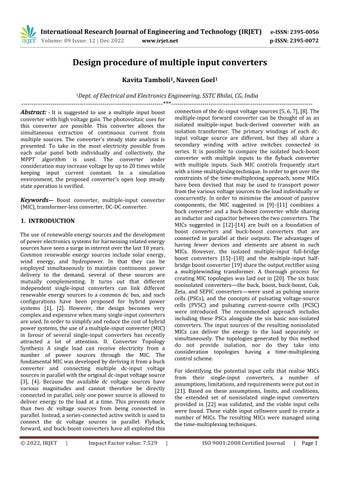
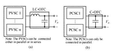
As shown in Fig. 1, each fundamental single-input dc-dc convertercanbedividedintotwobasiccells:aPSCandan output filter cell (OFC) (a). PVSCs and PCSCs are the two different types of PSCs. Given that the PVSC produces pulsating voltage, the corresponding OFC should be a voltage-typelow-passfilter,whichisessentiallycomposed of an inductor and a capacitor. LC-OFCs are this type of OFCs. Similar to how the PCSC supplies pulsating current, the corresponding OFC should be a current-type low-pass filter,which issimplyachievedbya capacitor.One variety of OFC is the COFC. The arrangements of a PVSC followed byanLC-OFCand,accordingly,aPCSCfollowedbyaCOFC, areshowninFigs.1(b)and(c).
We begin by going through the two main limitations that Kirchhoff's rulesplace onintegrating independentsources [24]. First off, parallel connections between two or more independent voltage sources are not possible due to Kirchhoff'svoltage law.Second, itis impossible to connect two or more independent current sources in series, in defiance of Kirchhoff's current law. Any synthesis regulationsforMICsthatmixmultiplePSCswillbesubject tothesefundamentallimitations.
Alistofthesynthesisproceduresisprovidedbelow.
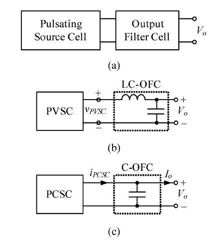
The kind of pulse sources being brought together determines the proper Kirchhoff's law, which is then utilised to define the connection style. Basically, many PCSCs, which are primarily current sources, can be connectedinparallel,andmanyPVSCs,whichareprimarily voltage sources, can be connected in series (b). It is clear that depending on the switching configuration, PVSCs in series and PCSCs in parallel can both produce electricity simultaneously.
Furthermore, as PVSCs are switching source cells, connecting them in parallel is possible without breaking Kirchhoff's rules, provided that they are not simultaneously delivering power, which would result in a direct parallel connection of voltage sources. In other words, assuming the appropriate switching configuration is in place, PVSCs can also be connected in parallel, as showninFig.2.(c).Similar tothis,asPCSCs are switching source cells, they can theoretically also be connected in series.
Given that the PCSCs do not provide power concurrently, currentsourcescanbeconnecteddirectlyinserieswithout deviating from Kirchhoff's principles. The current sources in PCSCs, including the independent and intermediate storageones,areachievedbyaninductorbehindavoltage source, despite the fact that they are not perfect current sources. For instance, we would need to turn on Q so that the input voltage would charge the inductor to saturation anddestroytheboostPCSCinordertostoptheboostPCSC inFig.3(a)fromsendingenergytotheload.Therefore,itis impossible to connect PCSCs in series in practise. We can offerthefollowingpotentialrelationshipsasaconclusion.
Fig.1Configurationsofsingle-inputconverter.(a)General configuration.(b)PVSCfollowedbyLC-OFC.(c)PCSC followedbyC-OFC.
Connection Rule 1: Several PVSCs can be connected in seriestogivepowerconcurrentlyoroneatatime,whereas several PCSCs can be connected in parallel. The resulting MICsenable the supplyof power from all input sourcesto the load either singly or concurrently, as was already described.
International Research Journal of Engineering and Technology (IRJET) e-ISSN: 2395-0056
Volume: 09 Issue: 12 | Dec 2022 www.irjet.net p-ISSN: 2395-0072
Connection Rule 2: With the appropriate switching configurations,several PVSCscanbe linkedin parallel and give electricity one at a time. A diode connected in series withthe switchor a switch thatisexplicitlyunidirectional mustbeusedinanonisolatedPVSC.
TheseverallinkedPVSCsinFig.2(a)and(c)canbeseenas a single PVSC, it should be highlighted.. The numerous connectedPCSCsdepictedinFig.2(c)canalsobeviewedas asinglePCSC.
In actuality, more than one PCSC can be connected in paralleltoaPVSC,andthisPSCconfigurationactsasa
voltage source. However, each parallel-connected PCSC wouldnotfunctionindependentlyifthePVSCorcombined circuit failed. Similar to a current source, a series connection between multiple PVSCs and a PCSC behaves similarlyandwouldfailifthePCSCfailed. Asaresult,such PSCcombinationsdonotresultinefficientMICs.
We begin by assuming that the OFC is the last cell to supply the load with constant dc voltage. We have two basictypesofOFCs,theLC-OFCandC-OFC,asdiscussedin SectionII.
Fig.2 Configurationsof(a)multiplePVSCsinseries,(b)multiplePCSCsinparallel,and(c)multiplePVSCsinparallel withappropriateswitchingarrangementtoensureeachPVSCdeliveringpowerindividually.
When a voltagesource-capacitor loop is closed or opened, switchingcreatesanincompatibleboundarystatethat leadstounendingcurrentorvoltageimpulses,accordingto fundamental circuit theory. Pulsing sources should be connected to the right kind of buffer cell in order to transfer power without creating incompatible switching conditions (storage element). Switched current can only interact with capacitive storage to prevent switching a current-source-inductor cutset, and switched voltage can only interface with inductive storage to prevent switching avoltage-source-capacitorloop.
Fig.3 Configurations of single-input converter. (a) General configuration. (b) PVSC followed by LC-OFC. (c) PCSC followedbyC-OFC.
The LC-OFC should be used to filter the voltage delivered from a PVSC and the C-OFC should be used to filter the currentdeliveredfromaPCSCwhenconnectingaPSCwith anoutputfilter.
International Research Journal of Engineering and Technology (IRJET) e-ISSN: 2395-0056
Volume: 09 Issue: 12 | Dec 2022 www.irjet.net p-ISSN: 2395-0072
The potential links between PSCs and output filters are outlinedinthefollowingrule
Fig.4BlockdiagramofMICtopologies.(a)CombinedPVSCs followedbyLC-OFC.(b)CombinedPCSCsfollowedbyCOFC.
Relationship Rule 3: A component of an MIC that is required is an output filter. Power from a PVSC should be filteredusinganLC-OFC,andpowerfromaPCSCshouldbe filteredusingaC-OFC.
A PSC is first connected to each power source. After that, several PSCs are aggregated and electricity is sent to the load via an output filter. In Fig. 4, a block diagram is displayed.
Three types of MICs can be derived for the two different PSCs,namelythe basicand hybridPSCs,byconnecting the resulting voltage or current to the right output filter. To make things simpler for the example, MICs are created by combiningjusttwoPSCs.
The synthesis procedure of this type of MICs takes the followingsteps.
Step 1: Choose PSCs from Figs. 2 and combine them accordingtoconnectionrules1and2.
Step 2: Cascade the combined PSCs with the appropriate outputfilter,accordingtoconnectionrule3.
Three groups of MICs are produced from the aforementioned procedure, depending on the connection styleofthePSCs,asshowninFig.2.
Fig.5TypicalderivedMICsgeneratedbyseriesconnection of(a)twobuckPVSCs,(b)onebuckPVSCandoneCuk PVSC
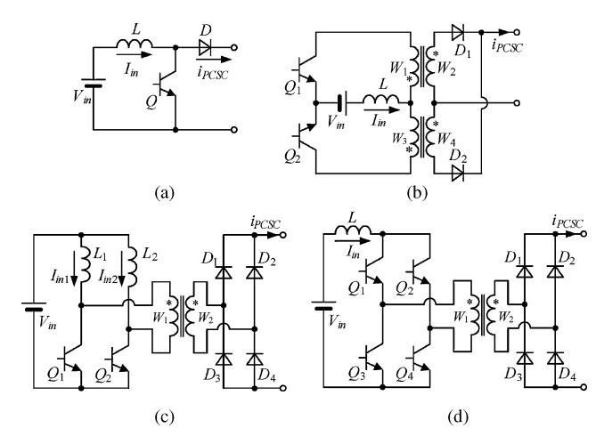
Fig.6TypicalderivedMICsgeneratedbyparallel connectionof(a)twoboostPCSCs,(b)oneboostPCSCand onebuck–boostPCSC.
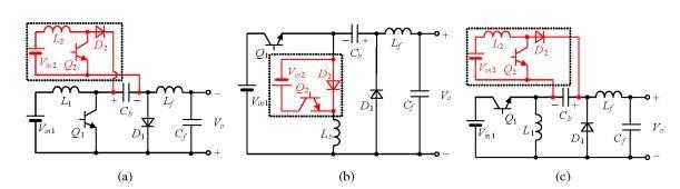
AsillustratedinFigs.2-4,there are manybasicPVSCs that can be coupled in series with one another or other PVSCs to create a variety of MICs. Six representative MICs are showninFig.5.
The first two MICs are shown in [20], and the remaining twoareproducedbyconnectingabuckPVSCinserieswith another buck PVSC, a Cuk PVSC, and a full-bridge PVSC, respectively.
Fig.7TypicalderivedMICsgeneratedbyparallel connectionof(a)twobuckPVSCs,(b)onebuckPVSCand oneCukPVSC.
The basic PCSCs can also be coupled in parallel with one another or other PCSCs, as shown in Figs. 5-7, to create a varietyofdifferentMICs.SixtypicalMICsareshowninFig. 6. The ones shown in Fig. 6(a)–(b) are produced by connecting two identical PCSCs in parallel, such as two flyback PCSCs, two half-bridge PCSCs, and two full bridge PCSCs.
International Research Journal of Engineering and Technology (IRJET) e-ISSN: 2395-0056
Volume: 09 Issue: 12 | Dec 2022 www.irjet.net p-ISSN: 2395-0072
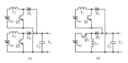
SixexemplaryMICsproducedbyparallelingtwoPVSCsare shown in Fig. 7. The PVSCs only retain one freewheeling diode; the others can be removed because they are superfluous. A diode should be placed in series with each switchingnetworkinlinewithconnectionrule2toprevent voltage sources from being connected directly in parallel. In Fig. 7(a), two buck PVSCs and one freewheeling diode D3areconnectedinparallel,andthediodesD1andD2are addedinserieswithQ1andQ2,respectively.InFig.7(b),a buck PVSC and a cuk PVSC are linked in parallel, with D2 acting as the freewheeling diode and D1 and D3 acting as the buck PVSC and cuk PVSC's respective series diodes, respectively.
TheMICsinFig.14allowallinputsourcestosendpowerto theloadeitherseparatelyorsimultaneously,incontrastto
the MICs in Figs. 5 and 6, which only allow one power sourcetotransferenergytotheloadatatime.
Itshouldbenotedthatthereareadditionalalternativesfor choosing voltage conversion ratios in the MICs created by Types II and III PCSCs or Types II and III PVSCs. The fundamental advantage of these MICs is that the output voltagecandifferfromtheinputvoltageineitherdirection.
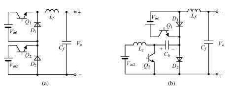
ThesamesynthesisprocesscanalsobeusedtocreateMICs withhybridPSCs.AhybridPSCwithtwoinputsourcesand one output filter is required to produce a two-input converter topology. As depicted in Fig. 8, the hybrid PSC feedspowertotheloadthroughanoutputfilter.SuchMICs weresuggestedin[20]
hybrid PSCs all have at least four input sources. C. Basic PSCandHybridPSCSynthesisofMICs
Fig.8MICsgeneratedbyone(a)boost-and-CukPVSC,(b) buck-and-ZetaPVSC,(c)boost-and-ZetaPVSC.
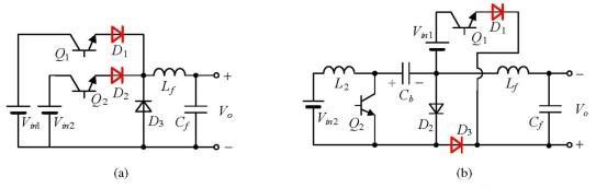
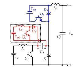
Connectionrules1and2alsoallowforthecreationofnew MICs by combining a number of basic PSCs and a number ofhybridPSCs.ThecircuitdesignsforMICsdepictedinFig. 10aremadebyconnectingabuckPVSCinserieswithtwo more PVSCs a boost-and-Cuk PVSC and a buckand-Zeta PVSC, respectively and finishing each with a cascade LCOFCstage.
TheboostPCSCisconnectedinparallel withthebuck-andbuck-boost PCSC, the boost-and-boost-SEPIC PCSC, and each is completed with a cascade C-OFC stage to produce MICs.
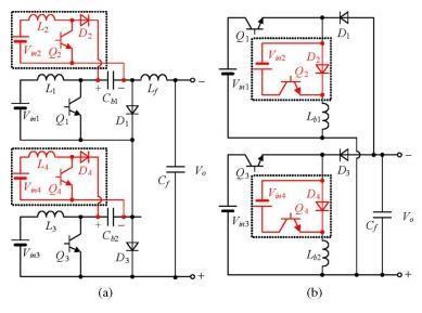
Fig.9MICsCircuit(a)twoboost-and-CukPVSCsinseries connectionand(b)twobuck-and-buck–boostPCSCsin parallelconnection
Similar to the synthesis of MICs using basic PSCs, several hybrid PSCs can be coupled to produce MICs in line with connectionrules1and2.Fig.9showstheconfigurationof a MIC created by two boost-and-Cuk PVSCs coupled in series with an LC-OFC (a). A C-OFC stage, two parallelconnected buck-and-buck-boost PCSCs, and a MIC are shown in Fig. 9(b) setup. Because the hybrid PSC contains various input sources, the MICs generated by different
Fig.10CircuitconfigurationsofMICsgeneratedbyseries connectionofonebuckPVSCandoneboost-and-CukPVSC.
where the diodes D1 to D4 act as the rectifier diodes, freewheelingdiodes,andseriesdiodes.Therefore,noother freewheelingdiodeisneeded.
Anorganizedprocessforcreatingvariousinputconverters hasbeenoutlinedinthisstudy.Thebuildingblocksforthe synthesisofmultiple-inputconvertershavebeenproposed as a collection of basic and hybrid PSCs, as well as output
International Research Journal of Engineering and Technology (IRJET) e-ISSN: 2395-0056
Volume: 09 Issue: 12 | Dec 2022 www.irjet.net p-ISSN: 2395-0072
filters. A collection of connection rules that can be used to methodicallyderivemultiple-inputconvertersisproposed. Although they are more complicated than multiple-input converters without intermediate storage, converters with intermediatestoragehavetheadvantageofhavingawider range of voltage conversion ratio options. Additionally, multiple-input converters with isolation can be made simpler,whichimprovestheirfunctionalityandusability.
[1] F. Iannone, S. Leva, and D. Zaninelli, “Hybrid photovoltaic and hybrid photovoltaic-fuel cell system: Economic and environmental analysis,” in Proc. IEEE Power Eng. Soc. Gen. Meeting, 2005, pp. 1503–1509.
[2] X. Kong and A. M. Khambadkone, “Analysis and implementation of a high efficiency, interleaved current-fed full bridge converter for fuel cell system,” IEEE Trans. Power Electron., vol. 22, no. 2, pp.543–550,Mar.2007.
[3] C. Liu and J. S. Lai, “Low frequency current ripple reductiontechniquewithactivecontrolina fuelcell power system with inverter load,” IEEE Trans. Power Electron., vol. 22, no. 4, pp. 1429–1436, Jul. 2007.
[4] E. H. Ismail, M. A. Al-Saffar, A. J. Sabzali, and A. A. Fardoun,“Afamilyofsingle-switchPWMconverters with high step-up conversion ratio,” IEEE Trans. Circuits Syst.I, Reg. Papers, vol.55, no.4, pp. 1159–1171,May2008.
[5] R. W. Erickson and D. Maksimovic, Fundamentals of Power Electronics, 2nd ed. Norwell, MA, USA: Kluwer,2001.
[6] W. Li and X. He, “A family of interleaved DC–DC converters deduced from a basic cell with windingcross-coupledinductors(WCCIs)forhighstep-upor step-down conversions,” IEEE Trans. Power Electron.,vol.23,no.4,pp.1791–1801,Jul.2008.
[7] W. Li and X. He, “An interleaved winding-coupled boostconverterwithpassivelosslessclampcircuits,” IEEETrans.PowerElectron.,vol.22,no.4,pp.1499–1507,Jul.2007.
[8] W. Li, Y. Zhao, Y. Deng, and X. He, “Interleaved converter with voltage multiplier cell for high stepup and high-efficiency conversion,” IEEE Trans. Power Electron., vol. 25, no. 9, pp. 2397–2408, Sep. 2010.
[9] Y.-P. Hsieh, J.-F. Chen, T.-J. Liang, and L.-S. Yang, “A novel highstep-up DC–DCconverter fora microgrid system,” IEEE Trans. Power Electron., vol. 26, no. 4, pp.1127–1136,Apr.2011.
[10] R. Xie, W. Li, Y. Zhao, J. Zhao, X. He, and F. Cao, “Performance analysis of isolated ZVT interleaved converter with windingcross-coupled inductors and switched-capacitors,” in Proc. IEEE Energy Convers. Congr.Expo.,Atlanta,GA,USA,2010,pp.2025–2029.
[11] W. Li, W. Li, X. He, D. Xu, and B. Wu, “General derivation law of nonisolated high-step-up interleaved converters with built-in transformer,” IEEE Trans. Ind. Electron., vol. 59, no. 3, pp. 1650–1661,Mar.2012.
[12] K.-C.Tseng,C.-C.Huang,andW.-Y.Shih,“Ahighstepup converter with a voltage multiplier module for a photovoltaic system,” IEEE Trans. Power Electron., vol.28,no.6,pp.3047–3057,Jun.2013.
[13] W. Li, Y. Zhao, J. Wu, and X. He, “Interleaved high step-up converter with winding-cross-coupled inductors and voltage multiplier cells,” IEEE Trans. Power Electron., vol. 27, no. 1, pp. 133–143, Jan. 2012.
[14] K.-C. Tseng and C.-C. Huang, “High step-up highefficiency interleaved converter with voltage multiplier module for renewable energy system,” IEEE Trans. Ind. Electron., vol. 61, no. 3, pp. 1311–1319,Mar.2014.
[15] K.-C.Tseng andC.-C. Huang, “A high step-up passive absorption circuit used in non-isolated high step-up converter,”inProc.IEEEAppl.PowerElectron.Conf. Expo.,LongBeach,CA,USA,2013,pp.1966–1971.
[16] K. Gummi and M. Ferdowsi, “Synthesis of doubleinput DC–DC converters using single pole triple throw switch as a building block,” in Proc. IEEE Power Electron. Spec. Conf., Rhodes, Greece, 2008, pp.2819–2823.
[17] V. A. K. Prabhala, D. Somayajula, and M. Ferdowsi, “Power sharing in a double-input buck converter using dead-time control,” in Proc. IEEE Energy Convers. Congr. Expo., San Jose, CA, USA, 2009, pp. 2621–2626.
[18] S. Lee, P. Kim, and S. Choi, “High step-up softswitched converters using voltage multiplier cells,” IEEETrans.PowerElectron.,vol.28,no.7,pp.3379–3387,Jul.2013.
[19] C.-M.Young,M.-H.Chen,T.-A.Chang,C.-C.Ko,andK.K.Jen,“CascadeCockcroft–Waltonvoltagemultiplier
International Research Journal of Engineering and Technology (IRJET) e-ISSN: 2395-0056
Volume: 09 Issue: 12 | Dec 2022 www.irjet.net p-ISSN: 2395-0072
applied to transformerless high step-up DC–DC converter,” IEEE Trans. Ind. Electron., vol. 60, no. 2, pp.523–537,Feb.2013.
[20] J. F. Dickson, “On-chip high-voltage generation in MNOSintegratedcircuitsusingan improvedvoltage multipliertechnique,”IEEEJ.Solid-StateCircuits,vol. 11,no.3,pp.374–378,Jun.1976.
[21] Y. Jang and M. M. Jovanovic, “Interleaved boost converter with intrinsic voltage-doubler characteristicforuniversal-linePFCfrontend,”IEEE Trans. Power Electron., vol. 22, no. 4, pp. 1394–1401,Jul.2007.
[22] M. Prudente, L. L. Pfitscher, G. Emmendoerfer, E. F. Romaneli, and R. Gules, “Voltage multiplier cells applied to non-isolated DC–DC converters,” IEEE Trans. Power Electron., vol. 23, no. 2, pp. 871–887, Mar.2008.
[23] Z. J. Shen, Y. Xiong, X. Cheng, Y. Fu, and P. Kumar, “Power MOSFET switching loss analysis: A new insight,” in Proc. IEEE Ind. Appl. Conf., Tampa, FL, USA,2006,pp.1438–1442.
Kavita Tamboli M.Tech student in 1Dept. of Electrical and Electronics Engineering, SSTCBhilai,CG,India