International Research Journal of Engineering and Technology (IRJET) e-ISSN: 2395-0056

Volume: 09 Issue: 11 | Nov 2022 www.irjet.net p-ISSN: 2395-0072

International Research Journal of Engineering and Technology (IRJET) e-ISSN: 2395-0056
Volume: 09 Issue: 11 | Nov 2022 www.irjet.net p-ISSN: 2395-0072
1Civil Engineering Department, Universitas Brawijaya, MT Haryono 167 Malang-65145 East Java Indonesia
2Faculty of Fisheries and Marine Science, Universitas Brawijaya, Veteran Malang-65145 East Java Indonesia
3Urban and Regional Planning Department, Universitas Brawijaya, MT Haryono 167 Malang-65145 East Java Indonesia ***
Abstract – A half-spherical space truss has a beautiful architectural view that can be applied as a roof on an aesthetic building such as a floating resort, bungalow, etc.For some cases, placing an opening such as a door or window can change the space truss structural configuration. A regular space truss structure has a good stability but changing the structural layout resulting some structural problems. This paper investigated the effect of placing an opening on the maximum axial forces of a half-sphericalspacetrussstructure. The result indicated that the gap can increase the axial forces by more than ten times the regular system. Hence, some structural treatments should be conducted to maintain the truss capacity.
Key Words: Axial force, Design, Opening, Space-truss
Somearchitectspreferahalf-sphericalspacetrussbecause ofitsbeautifulview,aerodynamicandeasytoassemblethe structural system. Truss is famous for its lightweight, effectivecost,andeasypreparation.Itcanbeappliedtolarge areawithafewinteriorsupports.Somereferencesdiscussed how to design and analyze the space truss structures. A reportbyH.KlimkeandJ.Sanchezintroducedthedesignand analysisofthespacestructure,includingthe3Dmodeling, continuum analogy, structural reliability, and the load carrying behavior [1] At the same time, other paper discussedaboutthedesignoftrussstructuresthroughreuse [2]
Thetrussstructureiseasytobemodified.Varioustypesof trussmodelshavebeenmade.Recentadvancedtypesofthe truss structures have developed significantly with a lot of researchhavediscussedtheirpropertiesandbehaviorsuch as the compressive behavior of tetrahedral lattice truss structures[3],mechanicalpropertiesofahierarchicaloctettrussstructure[4],thenailductilityontheloadcapacityofa glulam truss structure [5] and also the stability and load capacityofanelasto-plasticpyramidaltruss[6] Structural failurebehaviorwasalsodiscussedbythepreviousstudies astheprogressivecollapseofspacetrussstructuresduring earthquake[7],dynamicanalysisforprogressivefailureof truss structures considering inelastic post-buckling cyclic behavior [8], evaluation method for predicting dynamic collapseofdoublelayerlatticedspacetrussstructuresdueto
the earthquake motion [9] and also failure and energy absorption characteristics of advanced 3D truss core structures[10].
As a development of recent truss model variation, the presentstudyuseda half-spherical spacetruss.Thistruss model,next,willbeappliedasawall-roofstructureonthe floating resort bungalow. An ordinary roof structure does notneedanopening.Asawallapplication,therealwaysbe an opening, such as a door or window. This opening placement resulted in changes of the truss structural configuration. Irregularity in the structural system can significantlyaffectthestructuralcapacity,mainlytheaxial forces.Hencethispaperdiscussedtheaxialforcesofahalfsphericalspacetrussstructurewithanopeningcomparedto theregulartruss.
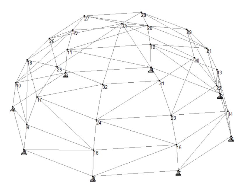
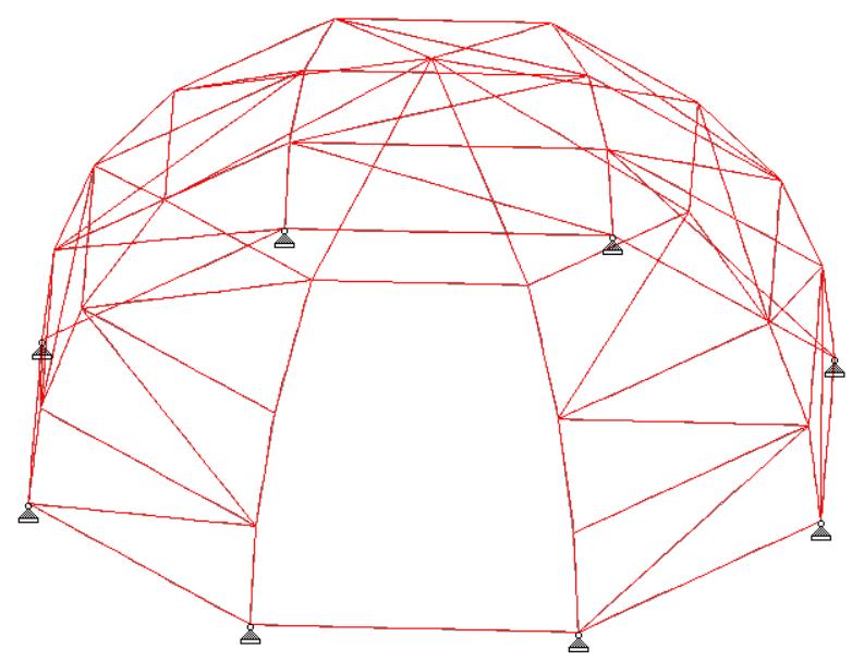
Ahalf-sphericalspacetrussmodelwaschosen.Thepresent analysisusedaSTAADProfiniteelementsoftware [11] to arrange the model and find the axial forces of the truss members. Two models were investigated, a regular halfsphericalspacetrussandahalf-sphericalspacetrusswithan opening.Theregularspacetrussmodelisshownin Fig-1, whilethestructurewithanopeningisshownin Fig-2 Four maintransverseframeswereusedwithananglebetween eachframeat45degrees.Inordertofindsuitablestructural integrity and stability, a basic triangular shape was used. This configuration enables the structure to ignore the bending moment contribution, as the truss structure can onlyresisttheaxialforces. Atotalof33nodesand88truss beammembersweremade.
International Research Journal of Engineering and Technology (IRJET) e-ISSN: 2395-0056
Volume: 09 Issue: 11 | Nov 2022 www.irjet.net p-ISSN: 2395-0072
Description Symbol Magnitude Unit
Outsidediameter OD 105 inc
Insidediameter ID 094 inc
Area A 110.918 mm2
Momentofinertia I 1664926 mm4 Radiusofgyration r 12251 mm
Fig -1:Aregularhalf-sphericaltrussmodel
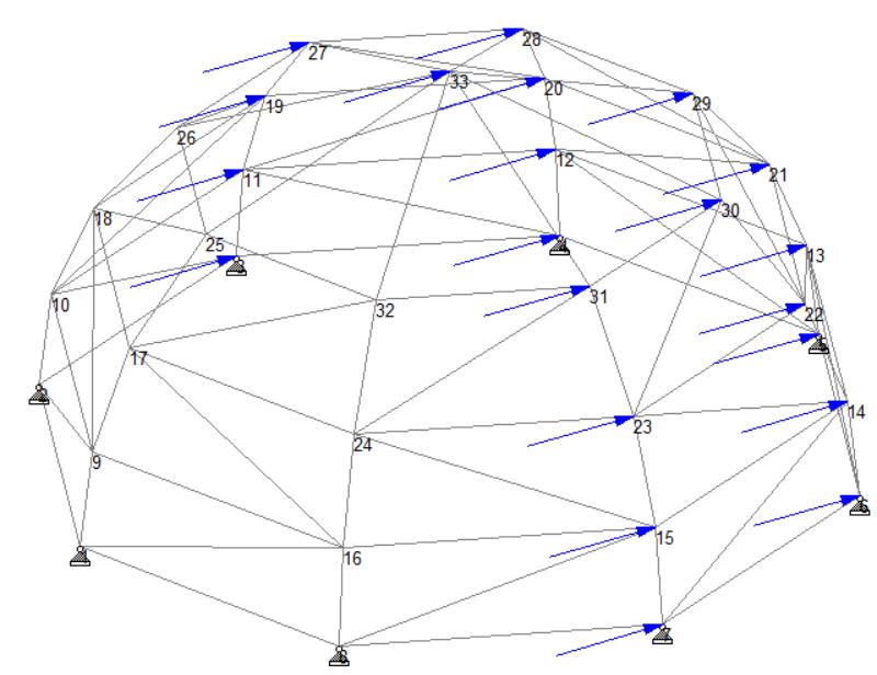
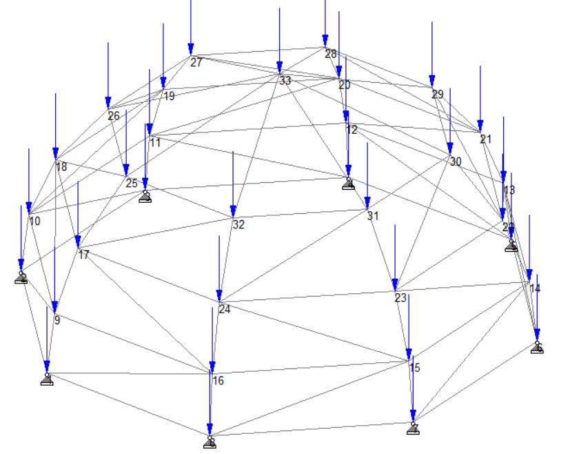
Threeloadtypes, deadload (DL),liveload(LL),andwind load(WL),wereappliedtothestructurewiththedirections shownin Fig-3 Thedeadloadwasappliedusingautomatic STAADPromenu.Theliveloadwasdeterminedaccordingto IndonesianStandard–minimumloadfordesigningbuilding andotherstructuresSNI1727-2020[12]as100kgapplied on each node. Finally, wind load was calculated using the basic load as 25 kg/m2 (for the non-coastal area), then converted to 21 kg on the half-structure nodes in a horizontaldirection.
Fig -2:Ahalf-sphericaltrussmodelwithopening
Thetrussstructure wasarrangedusing a pipe4/3SCH40 (USA)steelprofile.Thematerialandstructuralpropertiesof apresentlyusedprofileiswrittenin Table-1.Eachbottom nodeofthetrussstructurewassupportedbypinnedsupport asthetrussstructurecanonlycarryshearandaxialforces.
Table -1: Materialandstructuralpropertiesofpipe4/3 SCH40
Description Symbol Magnitude Unit
ElasticModulus E 205000 MPa
Specificgravity γ 7833 Kg/m3
Poisson’sratio φ 0.3Yieldstress fy 253 MPa
Ultimatestress fu 407 MPa
(a) Liveload(LL)
(b) Windload(WL)
Fig -3:Liveandwindloadsoftrussmodel
2022, IRJET | Impact Factor value: 7.529 | ISO 9001:2008 Certified Journal |
International Research Journal of Engineering and Technology (IRJET) e-ISSN: 2395-0056
Volume: 09 Issue: 11 | Nov 2022 www.irjet.net p-ISSN: 2395-0072
LoadcombinationswerealsomadeaccordingtoSNI17272020asfollows:
1.2DL+1.6LL
1.2DL+1.0LL+1.0WL
1.2DL+1.0LL+1.0WL
Theaxialforcesoutputwastakenfromthemaximumvalue ofthosethreeloadcombinations,whichconsistofmaximum tensionandaxial compressionforces.Theresultwasthen compared between the regular structure and the truss structurewithopeningsothattheopeninginfluenceonthe maximumstructuralforcescouldbeunderstandable.
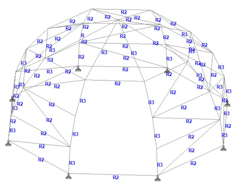
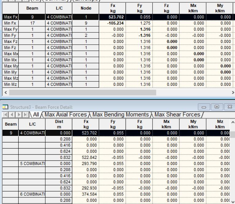
The result of axial forces from the present regular halfspherical truss system is written in Fig-4 Here, the maximum tension axial force of 523702 kg was found in beam number 9 while the maximum compression force foundinbeamnumber17was-105234kg.
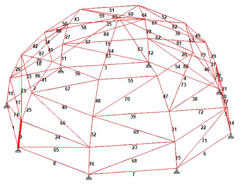
Fig -4:Beamaxialforcesforregulartruss
Iftheusedbeamsteelprofileaspipe4/3SCH40(USA)was checkedtocontrolthestructuralcapacity,itneedstodivide the examination for two types of axial forces which are tension and compression. For tension structural safety examination, the maximum tension axial force from STAAD.Prosoftwareiscomparedtothemaximumallowable structural tension capacity using the yield stress data multiplied by the steel cross-section area. From the data shown in Table-1, the maximum allowable force is calculatedas28062kg,whichislargerthanthemaximum tension force as 523702 kg, which means that the steel profile has fulfilled the safety requirement. For the compressionforceexamination,itisnecessarytocheckthe beam slenderness because the structural compression capacityissignificantlyinfluencedbytheslendernessratio. Theslendernessratiocanbecalculatedbydividingthebeam length and the radius of gyration. From the slenderness calculation as 211.5, the beam is categorized as a slender beam because the beam’s slenderness is more significant than200.Theslenderbeamscollapseduetobuckling.The buckling load (Pcr) can be determined using the Euler equationasfollows,where E istheelasticmodulus, I isthe moment of inertia, and L is the beam length. From the calculation,thebeambucklingloadof501.4kgislargerthan themaximumcompressionaxialforcesof105.234kgwhich meansthatthetrussalsofulfilsthesafetyrequirement.

International Research Journal of Engineering and Technology (IRJET) e-ISSN: 2395-0056
Volume: 09 Issue: 11 | Nov 2022 www.irjet.net p-ISSN: 2395-0072
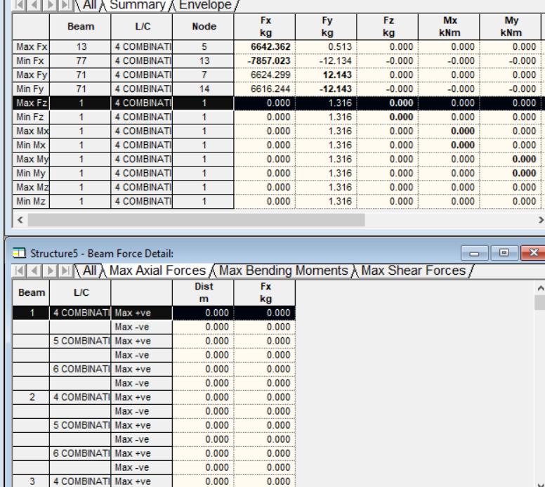
A half-spherical truss system with an opening that was analyzedusingsimilarstepstotheregularone.Theresultof analysis using STAAD.Pro software for the truss with an openingisshowninFig-5.Fromthisfigure,itwasfoundthat themaximumtensionof6642.362kgoccurredinbeam71, whilethemaximumcompressionaxialforceof-7857.023kg occurredinbeam77.
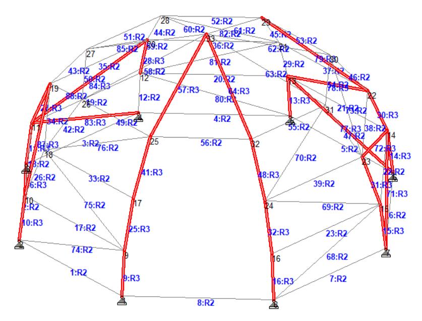
whichbeamsfromthetrusssystemthatresultintheaxial forcesmoresignificantthantheallowablestructuralcapacity. Fromtheexamination,thensomebeamswithoverlimitaxial forces need to be replaced using the more extensive steel profileuntiltheanalysismeetsthesafetyrequirement.From the investigation, then some beams that have over-axial forcesareshownin Fig-6.Thebeamswiththeredcolorwere thenreplacedusingthelargerdimensionofthesteelprofile aspipe2-1/2SCH40.Thematerialandstructuralproperties of this profile are written in Table-2 The structural dead load(DL)isautomaticallyadjustedbySTAAD.Prosoftware whensteelprofileisreplaced.
Fig -6:Thestructuralpartsthatneedsteelprofile replacement
Table -2: Materialandstructuralpropertiespipe2-1/2 SCH40
Description Symbol Magnitude Unit
Fig -5:
Asithasbeencalculatedfortheallowablestructuralcapacity ofpipe4/3SCH40steelprofileas2806.2kgand501.4kgfor tension and compression forces, respectively, the actual tension and compression forces as 6642.362 kg and7857.023kgismuchlarger,whichmeansthatthisdoesnot fulfill the safety requirement. For that, it needs to check
Indeed,replacingsomeofthetrussstructuralpartsisdifficult tobeappliedinrealfields.Butitisveryeconomicalbecause therewill beonlya slightdifferenceinthemaximumaxial
International Research Journal of Engineering and Technology (IRJET) e-ISSN: 2395-0056
Volume: 09 Issue: 11 | Nov 2022 www.irjet.net p-ISSN: 2395-0072
forcescompared to wholesteel profile replacement. Using steel profile pipe 2-1/2 SCH 40, the maximum allowable structuralcapacitiesas13567,09kg(tension)and-18178,11 kg (compression) resulted. If it then is compared to the maximumactualaxialforcesas6642.362kg(tension)and7857.023kg(compression),bothofthemhavemetthesafety requirement. The structural components need to be examinedforsafetyandconvenience.Fortheconvenience requirement,structuraldisplacementisneededtobechecked againsttheallowabledisplacementaccordingtothestandard requirement.
The present study discussed the comparison between a regularhalf-sphericaltrussstructureandthetrussstructure with opening to investigate the influence of placing an openingonthespacetrusssystemtothestructuralactual axial forces.TwomodelswereanalyzedusingSTAAD. Pro software. From the results that are mentioned in the previous chapter, it can be concluded that placing the openingresultedinasignificantincreaseinthemaximum axial forces.Forthiscase,theincreasereachedmorethan tentimescomparedtoaregulartrussstructure.Therefore, the opening placement disturbs the structural integrity, stabilityandregularity.Toimprovethestructuralcapacity, somebeammemberswithlargeforcesshouldbereplaced usingthelargerprofiledimension.Ifthesafetyrequirement hasbeenfulfilled,thenthestructuresneedtobeevaluatedin theconveniencerequirement.
[1] H. Klimke and J. Sanchez, “Design, Analysis and Construction of Space Structures,” The Mero Legacy, 2020.
[2] J.Brutting,J.Desruelle,GSenatoreandC.Fivet,”Design ofTrussStructuresThroughReuse,”Structures18,April 2019,pp.128-137,doi:10.1016/j.istruc.2018.11.006
[3] G. W. Kooistra, V. S. Deshpande and H. N. G. Wadley,”Compressive Behavior of Age Hardenable Tetrahedral Lattice Truss Structures Made From Aluminium,” Acta Materialia 52(14), August 2004, pp. 4229-4237.doi:10.1016/j.actamat.2004.05.039
[4] L. Weitao, D. Li and L. Dong, “Study on Mechanical Properties of a Hierarchical Octet-truss Structure,” Composite Structures 249, October 2020, doi: 10.1016/j.compstruct.2020.112640
[5] L.StehnandK.Borjes,”TheInfluenceofNailDuctilityon The Load Capacity of A Glulam Truss Structure,” EngineeringStructures26(6),May2004,pp.809-816, doi:10.1016/j.engstruct.2004.01.012
[6] M. V. B.Santana, P. B. Goncalves and R. A. M. Silveira, “Stability and Load Capacity of an Elasto-plastic Pyramidal Truss,” International Journal of Solids and Structures 171, October 2019, pp. 158-173, doi: 10.1016/j.ijsolstr.2019.04.011
[7] H. D. Zeng and J. Fan,”Analysis of The Progressive CollapseofSpaceTrussStructuresDuringEarthquakes Based on a Physical Theory Hysteretic Model,” ThinWalledStructures123,2018,pp.70-81.
[8] R.B.Malla,P.AgarwalandR.Ahmad,”DynamicAnalysis MethodologyforProgressiveFailureofTrussStructures Considering Inelastic Postbuckling Cyclic Member Behavior,”EngineeringStructures33(5),May2011,pp. 1503-1513,doi:10.1016/j.engstruct.2011.01.022.
[9] K.Ishikawa,S.OkuboandS.Kato,”EvaluationMethodfor PredictingDynamicCollapseofDoubleLayerLatticed Space Truss Structures due to Earthquake Motion,” International Journal of Space Structures 15(3), December2020,doi:10.1260/0266351001495099
[10] I. Ullah, M. Brandt and S. Feih,”Failure and Energy AbsorptionCharacteristicsofAdvanced3DTrussCore Structures,”Materials&Design92,February2016,pp. 937-948,doi:10.1016/j.matdes.2015.12.058.
[11] Bentley,STAAD.ProV8iTechnicalReferenceManual.
[12] Ministryforpublicworksandhousing,SNI1727-2020 Minimum Load for Designing Building and Other Structures,2020.
Dr. Eng. Lilya Susanti is a teacher andresearcheratCivilEngineering Department. She focused on research about the structural mechanics of steel and concrete, structuralmodeling,anddynamic analysis.

2022, IRJET | Impact Factor value: 7.529 | ISO 9001:2008 Certified Journal | Page664