International Research Journal of Engineering and Technology (IRJET) e-ISSN: 2395-0056

Volume: 09 Issue: 11 | Nov 2022 www.irjet.net p-ISSN: 2395-0072
International Research Journal of Engineering and Technology (IRJET) e-ISSN: 2395-0056
Volume: 09 Issue: 11 | Nov 2022 www.irjet.net p-ISSN: 2395-0072
Student, Dept. of Electronics Engineering, Shri Ramdeobaba College of Engineering and Management, Nagpur, Maharashtra, India ***
Abstract - Controller Area Network (CAN) is a low-cost communication protocol which is being used in various applications like automotive, medical, military, aviation, etc. Current CAN applications are based on the standard CAN 2.0 protocol. It was not designed for secure communication; although, it offers built-in error detection, robustness, speed and flexibility, the security side of CAN communication is highly underdeveloped. Research on in-vehicle CAN security primitives is difficult as it is hard to get a real vehicle for evaluation and development of these security primitives. The cost of research is considerably high, for some researchersthis creates a barrier, acting as a deterrence. This paper presents implementation of CAN on FPGA and evaluation of cryptographic algorithms as a security measure in CAN bus communication.
Key Words: FPGA, CAN bus, SJA1000, Xilinx Zynq, PetaLinux,ZYBO,Evaluation,Security.
Ifweconsideronlyautomobiles,therecouldbeasmanyas 100 Electronic Control Units (ECUs) all communicating through a single CAN bus system. Despite the functional benefits,theCANbussystemisvulnerabletocyber-attacks likereplayattacks,denial-of-service,andman-in-the-middle attacks. Security of any network can be assessed on three attributes: confidentiality,integrity,andauthentication.Many researchershavedemonstratedvarioussuccessful attacks which showed that CAN bus fails in all these three parameters [2,17,13]. Manufacturers understand these vulnerabilities and have started implementing security measureslike,NetworkSegmentation,IntrusionDetection System,Software-basedencryptionmethods.Butall these are computation intensive, have their own vulnerabilities, andareslower,thusreducingthedatatransferrateofsucha time-criticalsystem.Andaspointedoutby[3],considering thelifetimeofavehicle,itispossibletofindvulnerabilitiesin above mentioned measures and crack a static encryption key. For high stake applications like military-equipment, vehicles,aircraftsuchvulnerabilitiesarenotacceptable.A lot of research has been done in securing CAN communications[14-18];however,theseproposedsolutions havetheirownlimitationsandvulnerabilities.Developinga systemthatisabletomeetresourceconstraintsputbyCAN communicationsystemisarealchallenge.ModerndayECUs arerelativelyefficientandfastcomparedtotheonesuseda decadeago,hencesomeofthesolutionsproposedbysome
authors could be a viable option with some performance enhancingtweaks.However,athoroughevaluationofthese proposedmethodsisneededinordertoexploretheareasof improvements. This is a laborious, complicated and timeconsuming process, to streamline this process a versatile test-bed is needed that speeds up the entire chain of implementation, evaluation, and development and deployment. FPGAs based solutions can help to address thesechallengesbyenablingtrueflexibilityandscalabilityto addressthesecurityrequirementsofCANbuswithinherent hardware and software programmability. Rather than creatingabare-metalapplicationtorunonFPGAemulated CANcontroller,werelyonatest-bedthatrunsalight-weight Linuxkernelontop.Bare-metalapplicationaredifficultto debug as there are no fault management and error notificationsunlesstheyhavebeenexplicitlyimplemented andvalidated.Giventhescopeofourapplicationitisdifficult tofigureoutwhatexactlycouldgowrong,hencetheneedof atest-bedthathaserrorhandlingandpromptingabilitiesis needed,thisallowsforspeedydebuggingandevaluationof the proposed solutions, and speed up the development of new ones. In our experimental test-bed, we have used OpenCores SJA1000 controller, that has been modified to ignoreCANFDframes.ThisversionofSJA1000ismodified byCzechTechnicalUniversity,Prague(CTU)[1]andallows thiscontrollertoco-existandsenddataonCANFDnetwork.
The test-bed is built in two parts: hardware and software. ThedesignofhardwareisdoneusingXilinxVivadoDesign SuiteandisimplementedonZYBO(ZYnqBOard)thatuses Zynq All Programmable System on Chip Architecture. The SoCdesignhastwosubsystems:ProcessingSystem(PS)and ProgrammableLogic(PL).ThePS,isZynq-7000,hassoftware programmability features and takes over the job of controllingandcommunicatingwithPL.PLisXilinxArtix-7 FPGAwithconfigurableportsandbuses,andhashardware modules that are being emulated. The software design is donewiththehelpofPetaLinuxSDKtostreamlineembedded Linuxdevelopment.ThistoolhelpsustodevelopaBootable SystemImagethatconsistsofacustomCPU-optimizedLinux kernel, device drivers and bootloader configurations. The test-bedisnowreadyforfurtherimplementation,evaluation and development of security measures for CAN bus communications.Thissectionfurtherdiscussestheimportant elementsofhardwareandsoftwaredesign.
International Research Journal of Engineering and Technology (IRJET) e-ISSN: 2395-0056
Volume: 09 Issue: 11 | Nov 2022 www.irjet.net p-ISSN: 2395-0072
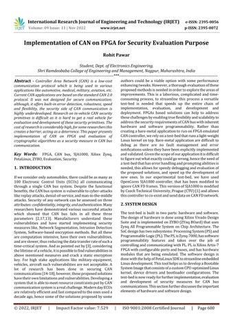
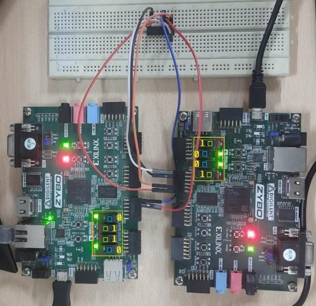
The hardware consists of SJA1000 controller, TJA1050 CAN trans-receiver, Zynq 7000 SoC, and other periphery circuits required for implementation of test-bed. Multiple instances of this test-bed can be used to connect and communicateonaCANbuslineforanalysisandevaluation of different security measures. For the demonstration of communicationbetweentwoCANnodes;Node1 andNode2 over the CAN bus, we perform a simple signal detection experiment.Wheninputisgiventoanyoneofthenodesby pressing the switch, for instance consider Node1, CAN communicationistriggeredandadata-framecorresponding to the signal is transmitted over the CAN bus, this signal data-frameispickedupbyNode2,itinterpretsitandtheLED assignedtotheswitch,turnsonoroff.i.e., theLED ofone nodeiscontrolledbyanothernode.Fig.1showstheblock diagramofaCANnode.
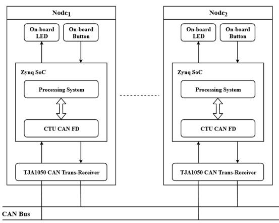
Fig -2:SchematicofImplementedSJA1000CAN Controller
It is an interface between CAN controller and physical bus.Itprovidesdifferentialtransmitanddifferentialreceive capabilitytotheCANcontroller.ItconvertstheTxandRx signalofcontrollertoCANHandCANLsignal.Itoffersgood performancewhenitcomestooptimalmatchingofoutput signals (CANH, CANL). The figure below shows block diagramofTJA1050.
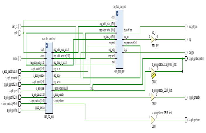
Fig -1:BlockDiagramofTest-bed.
It is a stand-alone controller for the Controller Area Network(CAN),mostlyusedwithinautomotiveandgeneral industrial environments. It has both CAN 2.0A (Standard CAN) and 2.0B (Extended CAN) protocol support, with bitratesupto1Mb/s.TheSJA1000thatisusedinthisproject isCANFDtolerantandiswritteninVeriloglanguage[1].It containstransmissionbuffer(TXB),receivingbuffer(RXB), bit timing logic (BTL), acceptance filter (ACF), bit stream processor (BSP), error management logic (EML), and interfacemanagementlogic(IML).ItusesanAPBinterface foronchipcommunicationwithmaster(i.e.,theprocessing system).SJA1000appearstoamasterasamemory-mapped I/O device. Independent operation of both devices is guaranteedbyaRAM-likeimplementationofitsregisters.Fig. 2showsschematicdiagramoftheimplementedSJA1000CAN controller.
Zynq-7000processingsystem(PS)isthemasterandan instance of SJA1000 in PL is the slave. Communication betweenmasterandslaveontheSoCisdonethroughAXI and APB buses respectively. AXI is designed for communication between blocks of IP on FPGA. AXI interconnectIPisusedtoconnectoneormoreAXImemorymapped master devices to one or more memory-mapped slavedevices.TheSJA1000IPhasAPBinterface,suitablefor low-speedcommunication.AnAXI-APBbridgeisneededto connectthisAPBslavetotheAXImaster.Interruptscoming fromtheCANcontrollerisconnectedtothePL-PSinterrupt portoftheprocessingsystem.TxandRxsignalsoftheCAN controlleraremappedtoIOpinsconnectedtothehighspeed Pmod (peripheralmodule)portsontheboard,itisanopen standarddefinedbyDigilentInc.forconnectingperipheral modules to FPGA. The Tx-Rx pair of the controller is converted to CANH and CANL signal by the transceiver moduleconnectedto Pmod port.Configurationandcontrol ofCANcontrollerisdonebythePSusingadrivercodewhich accesses the controller using the virtual memory address. Driverprogramisrequiredformodeselection,readingand writing messages to the controller, etc. A top-level applicationisrequiredtoreadsensorvalues,managekeys andconstructmessages.Astandaloneapplicationcouldbe created for this purpose but as discussed earlier our applicationrequiresadifferentapproach.ThecustomLinux kernelinthesystemhassupportforPython,C,andC+,this allowsforrapiddevelopmentanddeploymentofapplication program. The interface circuit diagram of our system is shownbelow.
International Research Journal of Engineering and Technology (IRJET) e-ISSN: 2395-0056
Volume: 09 Issue: 11 | Nov 2022 www.irjet.net p-ISSN: 2395-0072
valuesoftheSJA1000controllersetbytheSocketCANdevice driver.Withoutchangingthedefaultfilterregistervalues,we can directly access the controller through command line interface (CLI) to send/receive data to/from the bus. Another way is to set the values of filter register before initializing the CAN controller. Both of these methods are discussedbelow.
A Direct access to CAN controller: This can be done at OS levelusingCLIaswellasatapplicationprogramlevel.For simplicity, we show this process done at OS level, by executingthefollowingcommand.
Fig -3: InterfaceDiagramoftheTest-bednotusing transreceiver
TheprocessorintheProcessingSystembootsfirst,this allows for a software centric approach for Programmable Logicconfigurationwhichismanagedbyaprogramrunning on the CPU. After it starts, the Linux kernel probes the devices in the system, it gets to know about the devices present in the system from the Device Tree. A device's existenceinthesystem,itslocationonthebusfromwhichit may be accessed, and its configuration including its registers,interrupts,andothersettings areallspecifiedin thedevicetreeentry. DevicetreeentryofSJA1000isshown below.Fieldcalled‘compatible’isusedtospecifythenameof the driver associated to the device, ‘interrupts-’ field specifies on which pin number the interrupt of device is connectedandregspecifiestheaddressofdevice.
Code Snippet: sja1000_0:sja1000@43c00000{ compatible="nxp,sja1000"; interrupt-names="irq"; interrupt-parent=<&intc>; interrupts=<0294>; reg=<0x43c000000x10000>; reg-to-width=<4>; status="okay"; nxp,external-clock-frequency=<100000000>; };
The software realization of CAN node communication is doneintwoparts:InitializingtheSJA1000CANcontroller and creating an application program that can access the controllerforestablishingcommunicationwithothernodes onCANbus.
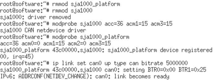
The system at this stage is ready to send all data and receivealldatausingdefaultarbitrationID(0x001),without filtering any messages, owing to the default filter register
Fig -4:InitializingtwoinstancesofSJA1000CAN controller.
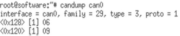
After initialization, the CAN controller can be now be directlyaccessedtosendandreceivemessage,alongwitha customordefaultarbitrationID.Thedirectaccessmethod ishelpfulwhenwewishtoreceiveandanalyseallthedata broadcastedovertheCANbus.Thefigurebelowshowsthe execution.
Fig -5:can1(Node2)sendingdataoverCANbususingID (0x123)
Fig -6:can0(Node1)receivingdataoverCANbusfrom CANnodehavingID(0x123)
B By changing filter register values: SocketCANdriverdoes nothavesupportforwritingthefilterregistersoftheCAN controllerbytheuser.Sincetheregistersarewrittenatthe time of insertion of device driver module and can’t be changedfrequently,thevaluesofallfourAcceptanceCode Register (ACR) and all four Acceptance Mask Register (ACR)arehardcodedasallzerosandallonesrespectively, whichmeansallthemessagesonthebuswillbereceived andsentinFIFOmanner.IntheSocketCANdriver,filtering isdoneatthekernellayerwhichdoesn’tmakesensefor our application since we have actual CAN protocol controller IP on the chip. We have modified he kernel module code, which allows us to change values of filter registers.Theshellcommandbelowshowstheprocessof changing filter register values after kernel module code modification.
International Research Journal of Engineering and Technology (IRJET) e-ISSN: 2395-0056
Volume: 09 Issue: 11 | Nov 2022 www.irjet.net p-ISSN: 2395-0072
two CAN nodes to communicate. When input is given to Node1 byflippingswitch,thisinputsignalissentoverCAN busandisreceivedbyNode2,Node2 thenextractsthesignal messagefromCANdata-frameandturnsonitsLEDthatis assignedtotheswitchofNode1.Inshort,theLEDsofNode2 is controlled by Node1 and vice-versa. Fig.9 shows the demonstration.Forthistest,acceptancefilterregistervalues were changed so that each node accepts data frame from anothernodeandfiltersoutitsowndataframe.
Fig -7:Showsprocesstochangefilterregistervalues
After the initialization of CAN controller, the system is ready to take part in communication. Apart from directly sendingdatathroughshellcommand,writinganapplicationbased program helps in realizing autonomous communication.Themessagethatiswrittentoorreadfrom CANdata-framedependsonthepurposeofapplication.
Createa socket andbind ittoCAN interface
Perform memory mappingof peripherals
Writing and Reading CANFrame
Fig -8:Programdesignflow
Triggering Communication
To ensure the functionality and viability of test-bed we carriedoutfollowingtests.
Communicationtestswereperformedwithandwithout using transreceiver for further evaluation. In this test discussedhere,insteadofusingtransceivermoduleswecan emulatethetransceiveroperationsimplybyANDingtheTx signalsfromthetwocontrollers.Forthispurpose,weusea two input AND gate. Tx signal of both the controllers are givenasinputstotheANDgateanditsoutputisconnected totheRxofboththecontrollers.Thisallowsforsuccessful arbitration.Aftertheinitializationofthesystem,werunour script in Linux shell of our test-bed. Python application runningatthetoplevelaccessesthememorymappedGPIOs. It reads sensor values, decides message identifier and attaches the corresponding count value to construct the message according to the protocol. Then it sends the messagetothecontrollerthroughSocketCANandreadsthe receivedmessagefromthecontroller.Theprogramenables
InFig.9.Aand9.BCANnodesonleft(Node1)withidentifier <0x128>sendsmessage0x06toNode2 andCANnodeson right(Node2)withidentifier<0x120>sendsmessage0x09to Node1. The received messages contain the status of the switchanddependinguponthestatus,correspondingLEDs are turned on. The switches highlighted in blue are in off stateandtheoneshighlightedingreenareinonstate,their statuscanbeseenotherboard.
Cryptographicalgorithmswereevaluatedontest-bedfor evaluationofitsperformance.Algorithmwereimplemented onapplicationlayer.Atime-delayanalysiswasperformedto see the delay caused by inclusion of these algorithms in communication.Thisdelayincludedtimetakenforsending and receiving message over CAN bus, time needed for encryptionanddecryptionofmessage.Anoverviewofthis operationisshownbelow.Forthistestabit-rate125Kb/s wasusedforreferenceandofmultipleiterationsoftestwere performedwith1000randommessagesineachtest.
International Research Journal of Engineering and Technology (IRJET) e-ISSN: 2395-0056
Volume: 09 Issue: 11 | Nov 2022 www.irjet.net p-ISSN: 2395-0072
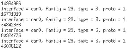
Fig -10. A: Line1-Messagetoencrypt
Line 2 - CAN controller of Node1 invoked after encrypted messagepassedtoit
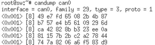
Fig -10. B:EncryptedmessagesentonCANbusbyNode1
Fig -11. A:PerformanceanalysisduringEncryption
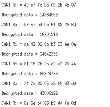
Fig -10. C:EncryptedmessagepickedupbyNode2 and decryptedtorevealtheoriginalmessage
Fig.10.Ashowstheplaintexti.e.,themessagetobesentto Node2byNode1,thisplaintextinconvertedintociphertext by cryptographic algorithms and is then sent to CAN controllerofNode1.Fig.10.Bshowstheencryptedmessage (plaintext) or ciphertext on CAN bus sent buy Node1. Fig. 10.C shows the ciphertext received by Node2 and is decrypted to reveal the original message (plaintext). The chartsbelowgiveanoverviewoftheresults.
Fig -11. A:PerformanceanalysisduringDecryption.
We have tested three different algorithms: Advance EncryptionStandard(AES),DataEncryptionStandard(DES), TripleDataEncryptionStandard(3DES).Wearerunningthe algorithms in (Cipher Block Chaining) CBC mode, in this mode block of plaintext are XORed with ciphertext of pervious of previous block and is then encrypted. The difference in encryption and decryption time of these algorithms is because in CBC mode encryption is done sequentially, where each cypher block is dependent on previousblock.However,incaseofdecryption,todecrypt nextcypherblockthereisnoneedofpreviousplaintext so decryptioncanbecompletelyparallelizedandismuchfaster inconcurrentsystems,likeFPGA. Theexecutiontimeand latencyinducedinpuresoftwareimplementationofthese algorithmsisshowntablebelow.
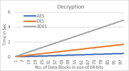
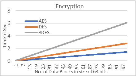
Table -1 Comparisonofoverheadbecauseofuseof CryptographicAlgorithms.
International Research Journal of Engineering and Technology (IRJET) e-ISSN: 2395-0056
Volume: 09 Issue: 11 | Nov 2022 www.irjet.net p-ISSN: 2395-0072
InTable1,entry1showstheactualnetworkloadachieved withoutuseofanycryptographicalgorithm. AESbeingthe fastestusesmorecomputationpower,followedbyDESand then3DES.Theseimplementedalgorithmscauseanincrease innetworkloadbecauseofthelimiteddatasizeofstandard CAN frame which is overcome by sending multiple CAN framesforonemessage.Thismaynotbeaproblemforlow trafficnetworkshoweverwiththeadvancementinmodern vehicles there is more integration of sophisticated technology(Ex:ADAS)thenumberofECUsareonlygoingto go up. Hence, it is imperative to look for a solution that satisfiesthetime-criticalneedsofCANbuscommunication.
The test-bed can be used to evaluate different proposed security measures and carry out analysis for areas of improvement. We have demonstrated test-bed’s functionalityandanalysedtheperformanceofcryptographic algorithms in CAN communication. This test-bed is a versatileoptionthatfacilitatesfastpaceddevelopmentand deployment.Applicationprogramcanbedevelopedinother systemandthencanbedirectlycopiedintothememoryof the test-bed. For any fine tuning or changes needed in program,itcanbedonedirectlybyaccessingtheprogram through the Linux shell in test-bed. This is helpful when iterativechangesaremadetoprogram.Thesystemdoesnot need to restart every time, all the changes can be made directlytoprogramwhilethetest-bedisonline.Moreover, thissystemgivestheabilitytodebugaprogramwhichisnot possiblewhenbare-metalapplicationiscreated,theerror handlingandpromptingabilityisjustanotheradvantageof this test-bed. This test-bed is intended for evaluation and development of security measures. Once a satisfactory analysis is carried out, later a bare-metal application or RTOS(RealTimeOperatingSystem)basedsolutioncanbe developedtoimproveexecutionspeed.
The functionality and viability of the test-bed has been verified through different experiments. The test-bed is simple,stableandpractical,andthuscanbeusedforfurther studies and evaluations. Hardware-based solutions are betterwhenitcomestoperformanceandsecurity,butare not versatile. Software based solutions are versatile but effectiveonlywhenhighperformanceCPUsareavailableand theyinducecommunicationdelay.Takingadvantageofhigh level of parallelism offered by FPGA and flexibility of EmbeddedSystemsitispossibletocomewithaversatileand high-performancesecuritysolutions.Basedonthefindings of subsequent tests, the primary goal would be to concentrateoncreatingaworkablesolutionforsafeguarding CANBuscommunications.
[1] OpenCores SJA1000 controller. Available at: https://canbus.pages.fel.cvut.cz/
[2]Koscher,Karl,etal."Experimentalsecurityanalysisofa modernautomobile." 2010 IEEE Symposium on Security and Privacy.IEEEComputerSociety,2010.
[3] Bozdal, Mehmet, et al. "Evaluation of can bus security challenges." Sensors 20.8(2020):2364
[4] Lin, Chung-Wei, and Alberto Sangiovanni-Vincentelli. "Cyber-security for the controller area network (CAN) communicationprotocol." 2012 International Conference on Cyber Security.IEEE,2012.
[5]Szilagy,Chris,andPhilipKoopman."Aflexibleapproach toembeddednetworkmulticastauthentication."(2008).
[6] Huang, Tianxiang, et al. " ATG: An Attack Traffic Generation Tool for Security Testing of In-vehicle CAN Bus"(2018)
[7] Payne, Bryson R. (2019) "Car Hacking: Accessing and Exploiting the CAN Bus Protocol," Journal of Cybersecurity Education, Research and Practice:Vol.2019:No.1,Article5
[8] K. Koscher et al., ``Experimental security analysis of a modern automobile,''in Proc. IEEE Symp. Secur. Privacy, Oakland,CA,USA,May2010,pp.447_462.
[9] (2014). The Lockheed Martin Cyber Kill Chain.[Online]. Available :http://cyber.lockheedmartin.com/hubfs/Gaining_the_Adva ntage_Cyber_Kill_Chain.pdf
[10]H.GustavssonandJ.Axelsson,``Evaluating_exibilityin embeddedautomotiveproductlinesusingrealoptions,''in Proc. 12th Int. Softw. Product Line Conf., Sep. 2008, pp. 235_242.
[12]K.Koscher et al.,``Experimentalsecurityanalysisofa modern automobile,'' in Proc. IEEE Symp. Secur. Privacy, Oakland,CA,USA,May2010,pp.447_462.
[13] S. Woo, H. J. Jo, and D. H. Lee, ``A practical wireless attack on the connected car and security protocol for invehicleCAN,'' IEEE Trans. Intell. Transp. Syst.,vol.16,no.2, pp.993_1006,Apr.2015.
[14]J.Schmandt,A.T.Sherman,andN.Banerjee,``Mini-MAC: Raising the bar for vehicular security with a lightweight messageauthenticationprotocol,'' Veh. Commun.,vol.9,pp. 188_196,Jul.2017.
[15]H.AbdulmalikandB.Luo,``UsingID-hoppingtodefend againsttargetedDoSonCAN,''in Proc. 1st Int.WorkshopSafe Control Connected Auton. Vehicles,2017,pp.19_26.
International Research Journal of Engineering and Technology (IRJET) e-ISSN: 2395-0056
Volume: 09 Issue: 11 | Nov 2022 www.irjet.net p-ISSN: 2395-0072
[16] L. Martin, P. Mundhenk, and S. Steinhorst, ``SecurityawareobfuscatedpriorityassignmentforautomotiveCAN platforms,'' ACM Trans. Des Automat. Electron. Syst.,vol.21, no.2,pp.1_27,2016.
[17]P.-S.MurvayandB.Groza,``DoSattacksoncontroller areanetworksbyfaultinjectionsfromthesoftwarelayer,''in Proc. 12th Int. Conf.Availability, Rel. Secur.,2017,p.71.
[19]GuidoBertoni,JoanDaemen,MichaelPeeters,andGilles VanAssche.KeccakSpecifications,2009.
[18]S.Woo,D.Moon,T.-Y.Youn,Y.LeeandY.Kim,"CANID ShufflingTechnique(CIST):MovingTargetDefenseStrategy for Protecting In-Vehicle CAN," in IEEE Access, vol. 7, pp. 15521-15536,2019,doi:10.1109/ACCESS.2019.2892961.
[20]Bellare,M.,Rogaway,P.(1994).EntityAuthentication and Key Distribution. In: Stinson, D.R. (eds) Advances in Cryptology CRYPTO’93.CRYPTO1993.LectureNotesin Computer Science, vol 773. Springer, Berlin, Heidelberg. https://doi.org/10.1007/3-540-48329-2_21
[21] Elinux.org. Available at: https://elinux.org/index.php?title=Python_Can&action=edit
[22] Digilent, Inc. Available at: https://digilent.com/reference/programmablelogic/zybo/start
2022, IRJET | Impact Factor value: 7.529 | ISO 9001:2008 Certified Journal