International Research Journal of Engineering and Technology (IRJET) e-ISSN:2395-0056

Volume: 09 Issue: 11 | Nov 2022 www.irjet.net p-ISSN:2395-0072
International Research Journal of Engineering and Technology (IRJET) e-ISSN:2395-0056
Volume: 09 Issue: 11 | Nov 2022 www.irjet.net p-ISSN:2395-0072
1PG Student, Department of civil Engineering, Sanketika Vidya Parishad Engineering College. 2 Assistant Professor, Department of civil Engineering, Sanketika Vidya Parishad Engineering College. 3 Principal, Sanketika Vidya Parishad Engineering College. ***
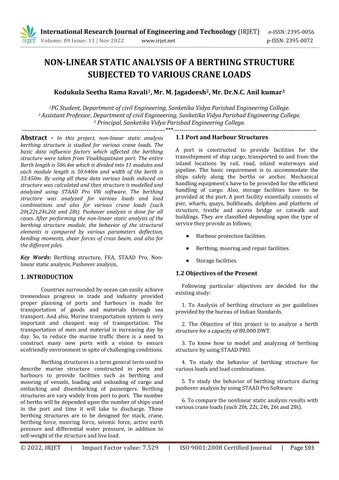
Abstract - In this project, non-linear static analysis berthing structure is studied for various crane loads. The basic data influence factors which affected the berthing structure were taken from Visakhapatnam port. The entire Berth length is 506.4m which is divided into 11 modules and each module length is 50.640m and width of the berth is 33.450m. By using all these data various loads induced on structure was calculated and then structure is modelled and analyzed using STAAD Pro V8i software. The berthing structure was analyzed for various loads and load combinations and also for various crane loads (such 20t,22t,24t,26t and 28t). Pushover analysis is done for all cases. After performing the non-linear static analysis of the berthing structure module, the behavior of the structural elements is compared by various parameters deflection, bending moments, shear forces of cross beam, and also for thedifferentpiles.
Key Words: Berthing structure, FEA, STAAD Pro, Nonlinearstaticanalysis,Pushoveranalysis,
Countriessurroundedbyoceancaneasilyachieve tremendous progress in trade and industry provided proper planning of ports and harbours is made for transportation of goods and materials through sea transport. And also, Marine transportation system is very important and cheapest way of transportation. The transportation of men and material is increasing day by day. So, to reduce the marine traffic there is a need to construct many new ports with a vision to ensure ecofriendlyenvironmentinspiteofchallengingconditions.
Berthingstructuresisatermgeneraltermusedto describe marine structure constructed in ports and harbours to provide facilities such as berthing and mooring of vessels, loading and unloading of cargo and embarking and disembarking of passengers. Berthing structuresarevarywidelyfromporttoport. Thenumber ofberthswillbedependeduponthenumberofshipsused in the port and time it will take to discharge. These berthing structures are to be designed for stack, crane, berthing force, mooring force, seismic force, active earth pressure and differential water pressure, in addition to self-weightofthestructureandliveload.
A port is constructed to provide facilities for the transshipment of ship cargo, transported to and from the inland locations by rail, road, inland waterways and pipeline. The basic requirement is to accommodate the ships safely along the berths or anchor. Mechanical handlingequipment’shavetobeprovidedfortheefficient handling of cargo. Also, storage facilities have to be provided at the port. A port facility essentially consists of pier, wharfs, quays, bulkheads, dolphins and platform of structure, trestle and access bridge or catwalk and buildings. They are classified depending upon the type of servicetheyprovideasfollows;
● Harbourprotectionfacilities.
● Berthing,mooringandrepairfacilities.
● Storagefacilities.
Following particular objectives are decided for the existingstudy:
1. To Analysis of berthing structure as per guidelines providedbythebureauofIndianStandards.
2. The Objective of this project is to analyze a berth structureforacapacityof80,000DWT.
3. To know how to model and analyzing of berthing structurebyusingSTAADPRO.
4. To study the behavior of berthing structure for variousloadsandloadcombinations.
5. To study the behavior of berthing structure during pushoveranalysisbyusingSTAADProSoftware.
6.Tocomparethenonlinearstaticanalysisresultswith variouscraneloads(such20t,22t,24t,26tand28t).
International Research Journal of Engineering and Technology (IRJET) e-ISSN:2395-0056
Volume: 09 Issue: 11 | Nov 2022 www.irjet.net p-ISSN:2395-0072
B. Santosh Kumar:
Intheprojectdescribedasuitablewaytodesigna new berthing structure with example of one of the proposed berthing structures in Visakhapatnam port. So, thefactorswhicheffectedonthestructureweretakeninto consideration of before analyzing and designing, the influence such as soil characteristics of the proposed location,environmentalconditionsandrangeoftraffic.
All the basic Data is taken from Visakhapatnam port which were supposed to be used in the project such as geotechnical data, environmental data, and traffic forecastingdata.Theentirelengthofberthis100mandis divided into 3 units of each 33.33 in length with an expansion joint of 40mm between successive units and proposed in the inner harbour, meant for handling liquid cargo like Sulphuric acid, Phosphoric acid, phosphoric acid,edibleoilsetc.
Thepresentinvestigationisanattempttoobserve the changes in design for different cases with respect to assumed model in which the pile founding level is same for all the piles. Three different cases are taken for which pile founding level has been varied which may arrive at site while construction and compared with the assumed modelwhichhassamefoundinglevelforallthepiles.Case 1 model has only 25% of the pile founding in (-) 19.0m levelandrestfoundingin(-)24.0mlevel.Case2modelhas 50% of the pile founding in (-) 19.0m level and rest founding in (-) 24.0m level. Case 3 model has 75% of the pile founding in (-) 19.0m level and rest founding in (-) 24.0m level. From above cases the forces and design has beencomparedwiththebasicassumedmodelinwhichall the piles are founded at (-)24.0m level. In this work the analysis and design is carried out by using SAP 2000 (Ver.14.1.0)application
Inthisconstructionthetypeofberthingstructure is two types they are Open type and Closed/Solid type of berthingstructure.Whiledesigningtheberthingstructure there are different type of live loads, they are stack load, craneload, BGML load,truck load,Mooring force etc..,are actingonthedeckslabofberthingstructure.Toresistthe all the load there is need to provide different structural elementstheyT-ShapedDiaphragmWall,MainCrosshead Beam, Vertical pile, Raker pile/ Anchored Wall/ Tie Rod. Especially to resist the horizontal force the structural elements like Raker Pile or Anchored Wall or Tie Rod are used. In construction type of berthing structure there are two types they are Open type and Closed/Solid type of berthingstructure.Whiledesigningtheberthingstructure
there are different type of live loads they are stack load, craneload, BGML load,truck load,Mooring force etc..,are actingonthedeckslabofberthingstructure.Toresistthe all the load there is need to provide different structural elementstheyT-ShapedDiaphragmWall,MainCrosshead Beam, Vertical pile, Raker pile/ Anchored Wall/ Tie Rod. Especially to resist the horizontal force the structural elements like Raker Pile or Anchored Wall or Tie Rod are used.
The entire berth of 225m length divided into 5units each 51m long. The plan dimensions of deck slab berthingstructureofeachunitwere51m(17panelsof3m width)x17.2m.EachunitconsistsofT-Shapeddiaphragm wall (TDW)of17No’s.TheT-shapeddiaphragmwall was connected at the top through a cellular deck Main Cross Head Beam (MCHB) of 2.80 meters depth to a series of vertical pile and racker pile on rear side. Berthing structure was assumed to be fixed at junction of diaphragm wall/pile and Main Cross Head Beam. All the members of the structure were assumed to be homogenous, isotropic and having the same Elastic modulusbothincompressionandtension.
G. T. Naidu:In this study the structural behavior of the components of berthing structure subjected to variable stack load with and without mooring force conditions. Methods/Statistical Analysis: Linear static analysis was performedontheberthingstructuresubjectedtovariable stackloadwithandwithoutmooringeffects.
From this study, equations related to bending momentandaxialforceofstructuralmembersofberthing structure has been obtained. A Monte Carlo simulation method was adopted for generation of random numbers usingMATLABsoftware.
The entire berth of 255m length is divided into 5 units of 51m long. Each unit consists of T- Shaped Diaphragmwalls(TDW)of17Nos,Rakerpiles(RP)of700 mm (diameter) of 19 Nos and Vertical Piles (VP) of 850 mm (diameter) of 17 Nos. The T-shaped diaphragm wall was connected at the top through a cellular deck Main CrossHeadBeam(MCHB)of2.80metersdeeptoseriesof verticalpilesandrakerpilesonrearside.
This design project is focusing on analysis and designof2ndpassengerberthatBeyporeport,Kozhikode. It’s an open piled bored cast-insitu structure and lying in the seismic zone III. The berth is to be designed for a vessel having capacity of 5000DWT. The structure is subjectedtovariousforcesandcombinationssuchas,High tide, Earthquake, High winds, heavy live loads as per IS: 4651-1983. A model was generated using STAADPro
International Research Journal of Engineering and Technology (IRJET) e-ISSN:2395-0056
Volume: 09 Issue: 11 | Nov 2022 www.irjet.net p-ISSN:2395-0072
software and analysis was conducted with appropriate loadsactingonthestructure.Itwasobservedthatseismic force was nominal since Beypore being located in seismic zone III. This research is an attempt to understand the concept of design and analysis of berthing structures underdifferentconditionsofloading.
The conceptual layout should include the length, width, dredge level, top level, location of beams for handling equipment, spacing of bollards and fenders and configuration of the structure. The configuration includes the arrangement of piles, deck system and dimensions of variousstructuralmembers.Thesizeofberthingstructure depends on the principal dimension of the large vessel to be handled, area required for transit shed, number of rail tracks, truck lines, crane rail and width of apron required toaccommodatemooringfacilitiesandutilityservice.
Oncethedimensionalrequirementforastructure hasbeendefined,itbecomesnecessarytodetermineloads of the structure. Because Loads are the primary consideration in any structuredesign because they define the nature and magnitude of hazards are external forces that a structure must resist providing a reasonable performancethroughoutitslifetime.
● Deadload:[IS875-1987PartI]
● Liveloads[IS4651(PartIII)-1974]:
● Truckloadinganduniformloading[IS4651(Part III)–1974]:
● BerthingLoad[IS4651(PartIII)–1974]:
● MooringLoad[IS4651(PartIII)-1974]:
● Seismicload[IS1893-Part(1)]:
● EarthPressure[IS4651(PartIII)-1974]:
● HydrostaticPressure[IS4651(PartIII)-1974]:
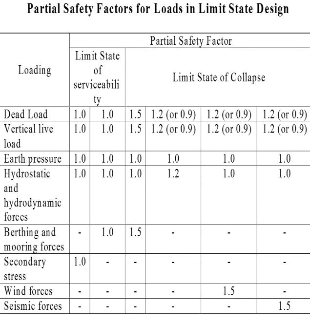
3.3.
Fig.3.1 LoadCombinations
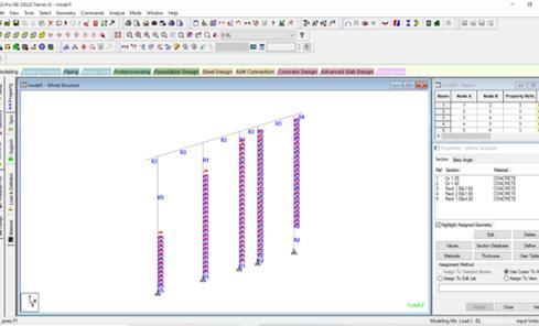
Thestructuralmodelsmustallowconsideringthe effectsofmovementsanddeformationsinthosestructures or part thereof, where second-order effects increase the effects of the actions significantly. The modeling of the entirestructureisdoneinSTAADPROsoftware.
The following cases are considered in the structural analysisofberthingstructure,theyare:
Case1:Berthingstructurewith20tcraneload.
Case2:Berthingstructurewith22tcraneload.
Case3:Berthingstructurewith24tcraneload.
Case4:Berthingstructurewith26tcraneload.
Case5:Berthingstructurewith28tcraneload.
Table -1: PrimaryDataofBerthingStructureAnalysis
LengthofTheBerthingStructure= 560m
WidthofTheBerthingStructure= 33.45
NumberofModules= 11
ModuleDimensions= 50.6x33.45(m)
Draft= 28m
DWT= 80,000
SeismicZone= II
ResponseReductionFactor= 3
ImportanceFactor 1.5
International Research Journal of Engineering and Technology (IRJET) e-ISSN:2395-0056
Volume: 09 Issue: 11 | Nov 2022 www.irjet.net p-ISSN:2395-0072
SoilType= II
CrossBeams= 1600x1800 (mm)
RetainingBeam= 1600x2000 (mm)
Diaphragmwall= 1000x4000
DiameterofPiles(A,B)= 1250(mm)
DiameterofPiles(C,D)= 1400(mm)
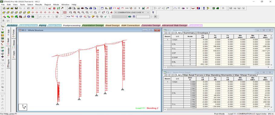
Inthispresentchapter,theresultsacquiredfordistinct berthingstructuremoduleforvariouscraneloadcasesare presented. The evaluation is carried out in STAAD Pro software.AfterperformingtheNonlinearstaticanalysisof structure is taken into consideration, their behavior is analyzed and compared in phrases of following parameters.
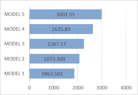
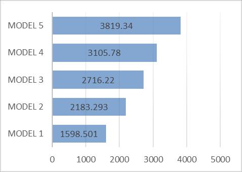
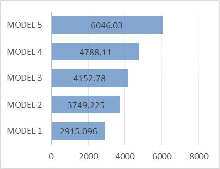
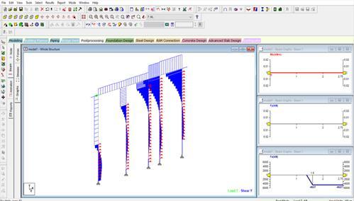
Fig.5.1 BendingMomentResultsofaCrossBeam
Fig.4.1 BerthingStructure
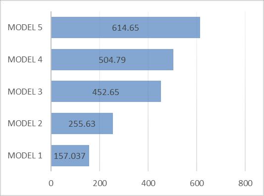
Fig.4.2 BendingMomentResults
Fig.5.2 ShearForceResultsofaCrossBeam
Fig.4.3 ShearForceResults
Fig.5.3 BendingMomentResultsofaDiaphragmWall
2022, IRJET | Impact Factor value: 7.529 | ISO 9001:2008 Certified Journal | Page 596
International Research Journal of Engineering and Technology (IRJET) e-ISSN:2395-0056
Volume: 09 Issue: 11 | Nov 2022 www.irjet.net p-ISSN:2395-0072
Fig.5.8 ShearResultsofBRowPile
Fig.5.4 ShearForceResultsofaDiaphragmWall
Fig.5.9 BendingResultsofCRowPile
Fig.5.5 BendingResultsofARowPile
Fig.5.6 ShearResultsofARowPile
Fig 5.10 ShearResultsofCRowPile
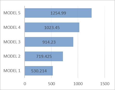
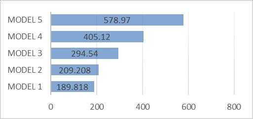
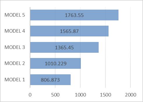
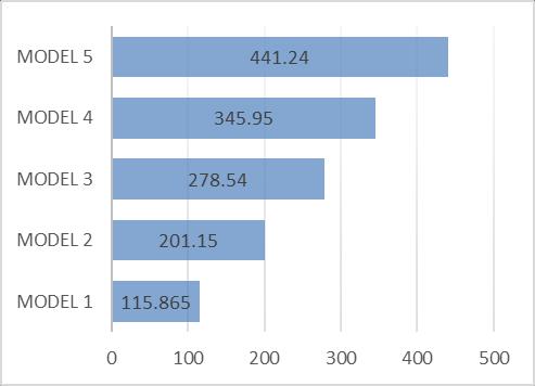
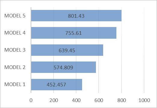
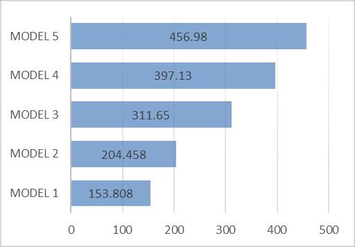
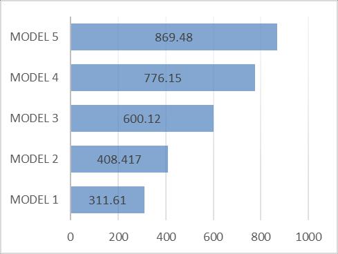
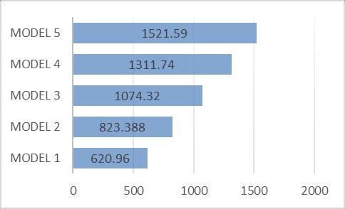
Fig.5.7 BendingResultsofBRowPile
Fig.5.11 BendingResultsofDRowPile
2022, IRJET | Impact Factor value: 7.529 | ISO 9001:2008 Certified
International Research Journal of Engineering and Technology (IRJET) e-ISSN:2395-0056
Volume: 09 Issue: 11 | Nov 2022 www.irjet.net p-ISSN:2395-0072
● The Percentage of variation of bending moment and shear force results due to various crane loads are 21.28%,10.10 %,15.37% and 5.71 % and 42.77%, 27.78%,19.48%,and21.59%respectivelyforBpile.
● The Percentage of variation of bending moment and shear force results due to various crane loads are 20.12%,26.01 %, 12.79% and 11.20 % and 9.26%, 28.97%,27.29%,and30.02%respectivelyforCpile.
● The Percentage of variation of bending moment and shear force results due to various crane loads are 26.30%,21.30%, 10.67% and 18.44 % and 38.56%, 43.52%,10.32%,and17.87%respectivelyforDpile.
In this project, non-linear static analysis berthing structure module is studied. For the purpose of the study the basic data influence factors which affected the berthing structure were taken into consideration, before analyzinganddesigning,suchassoilcharacteristicsofthe proposedlocation, environmental conditionsand rangeof traffic which will be used in the project is generally taken from Visakhapatnam port. The entire Berth length of 50.640mandwidthoftheberthis33.450m.TheBerthhas been modeled analyzed by using STAAD Pro Software. From the comparison of non-linear static analysis results for various crane loads the following conclusions were drawn.
● Fromthestudy,itwasconcludedthattheinfluenceof variableCraneloadhaseffectontheBendingMoment and shear force results of the cross beam, diaphragm wallandverticalpilesoftheberthingstructure.
● Based on study here load combinations of (0.9DL + 0.9LL + 1.2DWP + 1EP), (1.2DL + 1.2LL + 1.2DWP + 1EP)gotthemaximumresults.
● The Percentage of variation of bending moment and shear force results due to various crane loads are 22.24%, 9.71%,13.71% and 20.85% and26.78%, 19.62%,12.54%, and 18.68% respectively for cross beam.
● The Percentage of variation of bending moment and shear force results due to various crane loads are 10.16%, 8.55 %, 13.98% and 12.18 % and 24.58%, 23.35%, 18.09%, and 13.79%respectively for diaphragmwall.
● The Percentage of variation of bending moment and shear force results due to various crane loads are 23.70%,31.94 %, 22.67% and 10.73 % and 24.77%, 34.39%,21.52%,and13.09%respectivelyforApile.
● Pushoveranalysisiscontemplatedasaneffectivetool toassessthecapabilityof structureforseismic forces and for this reason it is expected the actual behavior ofthestructureduringearthquake.
● This proves that the analysis carried out using Pushover method is more effective as it studies the real time behavior of the structure and brings efficiencyintermsofcosttoo.
● It is found that the results of analysis of the berthing structureusingSTAADPro.softwareareveryusefulin thedesignofthestructuresaswellastoundertakethe performanceanalysisoftheconstructedstructures.
● Extension of this work needs to be considered for variousstackandmooringloads.
● And influence of raker pile on berthing structure performance.
1. AnalysisandDesignofDockBerthStructurebyB. Santosh Kumar: MARCH [2016], IJSART - Volume 2Issue3,Pageno-8-16.
2. AnalysisandDesignofBerthingStructuresfor HighSeismicZonesbyLaxmanRajwani.
3. Analysis and Design of Passenger Berthing Structure by Augustina- Feb -2017, Volume: 04 Issue:02,pp.67-77
4. Analysis and Design of a Quay Berthing Structure by S. Nagarjuna- Aug 2018, Volume Issue 4, July, pp.33-39.
5. Finite Element Analysis of Berthing Structures by Anjana S Rao- April-2018, Volume 9, Issue 4, pp.199-124.
International Research Journal of Engineering and Technology (IRJET) e-ISSN:2395-0056
Volume: 09 Issue: 11 | Nov 2022 www.irjet.net p-ISSN:2395-0072
6. Analysis and Design of Berthing Structure by VarunaBelagavi,July2017,Volume8,Issue7,pp. 1111–1124.
7. A Study On Behaviour Of Structural Elements Of BerthingStructureWithRakerPileAndAnchored Wall by G.T. NAIDU (IJCIET) Volume 8, Issue 7, July2017,pp.1111–1124.
8. Analysis And Design of a Heavy Cargo Berthing Structure by B Raghava Maheedhar (JETIR )Volume5Issue2February-2018
9. Study on the Structural behavior of Berthing Structure due to Variable Stack Load by G. T. Naidu-December2016,Vol9(45),ijst,pp.1-6.
10. An Approach on Optimization of Berth Structure at Port Sectors for Handling Bulk Cargo and Containers by Mr. Deekshith Shetty- July-2015, Vol.4,Issue07,(IJERT),pp.915-918.
11. ApplicationofForcesActing onJetty Structure by HimeshB.Chopra-May2015,Volume1,Issue11, pp.83-91.
12. Structural System Evaluation of Jetties by M. Rajkumar- September 2016, Volume 3, Issue 03, pp.153-160.
13. Reliability Based Analysis of Berthing Structure Subjected to Variable Crane Load by G. T. NaiduNumber7(2017),Volume12,pp.1123-1128.
14. IS 1893 (Part 1): 2002 Indian Standard Criteria for Earthquake Resistant Design of Structures, Part 1 General Provisions and Buildings, (Fifth Revision).
15. IS 875 (Part 2): 1987: Indian Standard Code of Practice for Design Loads (Other Than Earthquake) for Buildings and Structures, part 1 dead loads - unit weights of building materials andstoredmaterials(SecondRevision)
16. IS 4651 (Part 3): 1974: Indian Standard Code of Practice for Planning and Design of Ports and HarboursPartIiiLoading(FirstRevision).
Kodukula Seetha Rama Ravali isa student of M. Tech in Structural Engineering, Department of civil Engineering, Sanketika Vidya Parishad Engineering College, Visakhapatnam,AndhraPradesh.

Mr. M. Jagadeesh, his currently working as an Assistant Professor in the Department of civil Engineering, Sanketika Vidya Parishad Engineering College, Visakhapatnam, Andhra Pradesh. His area of interest is High rise buildings,FEA.