International Research Journal of Engineering and Technology (IRJET) e-ISSN:2395-0056

Volume: 09 Issue: 11 | Nov 2022 www.irjet.net p-ISSN:2395-0072
International Research Journal of Engineering and Technology (IRJET) e-ISSN:2395-0056
Volume: 09 Issue: 11 | Nov 2022 www.irjet.net p-ISSN:2395-0072
1M. tech Final Year Student, Dept. of Civil Engineering, GNIOT, Greater Noida, U.P, India 2Assistant Professor, Dept of Civil Engineering, GNIOT, Greater Noida, U.P, India ***
Abstract - When an earthquake occurs, it causes enormous damage in terms of property loss, human lives, and structural collapse. As a result, structural remodeling is a must. Damping Contributes significantly to Earthquake Resistant Structures' overall design by reducing their ability to deform when loaded from the sides. There are a variety of damper options available. Fluid viscous dampers (FVD) are employed in this study to gauge the reaction of reinforced concrete structures (RCB). The time period is reduced to 90% by employed FVD in Time History analysis. Structures' Base Shear is reduced by 70% while using FVD250.
Key Words: Damping,FVD,timeperiod,Baseshear
One of the most common civil engineering disasters is earthquake.Seismicactivitycausesstructuraldeterioration in buildings. Earthquake-resistant systems may be implementedtoimprovethebuilding'scapacitytowithstand earthquakes. The damper is one of the most common and effectiveearthquakeresistancemeasures.Throughoutthe building. In a passive control system, seismic energy is dispersed. Inthecaseofan earthquake,thisdevice flexes. Dams absorb earthquake energy. dampens ground movement during earthquakes by dispersing it structure. Thereareseveraldampersonthemarketnow,includingpall friction dampers Stabilizer, such as a mechanical or hydraulicstrutora damper installedona strut.Aviscous liquid. The FVD damper is one of the most effective and easiesttoinstalldampers.
Energyisdispersedinthisdamperbytheuseofaviscous fluidcontainedwithinacylinder.Asaresultoftheirsimple installation, versatility, and collaboration with other components,viscousdampersmaybeusedinawiderange ofdesignandretrofitapplications.
Theprimarygoalofstructuralanalysisistodeterminean object'sresponsetoaforce.People,furniture,wind,snow, etc.canallcontributetothisactivity,butitcanalsobethe resultofanearthquake,anearbyexplosion,orsomeother type of stimulation. All of these loads, including the
structure'sownweight,areinherentlydynamicsincethey weren'tpresentatsomeearliermomentintime.Staticvs. dynamic analysis may be distinguished based on whether theappliedactionhassufficientaccelerationincontrastto thestructure'sinherentfrequency.Inertiaforces(Newton's first law of motion) can be neglected if a load is applied slowlyenough.Thissimplifiesthestaticanalysis.Asaresult, structuraldynamicsisasortofstructuralanalysisthatdeals with dynamic loads. It is possible to employ dynamic analysistofinddynamicdisplacements,timehistories,and modalanalysis.
B. S. Taranath in “Building Design for Tall Buildings" complex non-linear time is necessary for seismic ground movements,whicharethencomparedtothedesignsatisfies thespecifiedsafetylevel.
Liya Mathew & C. Prabha Itwasreportedin"EffectofFluid Viscous Dampers in Multi-Storied Buildings" in 2014 that new protection methods had been created to increase earthquake safety and minimize structural damage.1 The fluidviscousdamper(FVD)isprominentlyfeaturedinthis application. This work also studies reinforced concrete structures
1. Buildingswithsquareandrectangulardesigns,with andwithoutFVD,willbecomparedfortheirseismic reaction.
2. TodeterminetheeffectsofFVDonthestructure's displacements.Todeterminethereductioninbase shearinRCstructuresbytheuseofFVD.Structures thathaveanddon'thaveFVDcanbestudiedtosee howthetimeperioddiffers.
3. Compare FVD structures to Time History and Pushover.
In a modal analysis, the frequency modes or natural frequencies of a system are calculated, but the full-time historical response to an input is not always included. a
International Research Journal of Engineering and Technology (IRJET) e-ISSN:2395-0056
Volume: 09 Issue: 11 | Nov 2022 www.irjet.net p-ISSN:2395-0072
system's inherent frequency simply depends on the structure'sstiffnessandthemassitcontains(includingselfweight).Loadfunctionisn'tanissue.
Thisishowit'sdone:
1. Determine the inherent modes and natural frequenciesofastructure.
2. Calculateeachmode'sanswer.
TheETABScomputerapplicationisusedforthebuilding's studyanddesign.Someofthe mostessentialfacetsofthe modellingprocessarecoveredinthefollowingsections.
1. Definingtheslabsections
2. Staticevaluationofequality
3. The lateral load pattern in multimodal or SRSS systems
Step1:CalculationofModalMatrix
Step2:CalculationofEffectiveForceVector
Step3:CalculationofDisplacementResponseinNormal Co-ordinates
Step4:CalculationofDisplacementResponseinPhysical Co-ordinates
Step 5: Calculation of Effective Earthquake Forces at Each Storey
ATC 40 and FEMA 273 hinge properties are preprogrammedintotheETABS,butitalsoallowsyoutoenter custom material or hinge properties. There is a P-M2-M3 (PMM) hinge that yields based on the interaction of the columnaxialloadandbendingmomentwhenthebuildingis subjectedtolateralloading.ETABSonlydealswithbuildings whereuncoupledmomentM2andM3,TorsionT,axialforce pandV2andV3forcedisplacementrelationscanbedefined andthecolumnaxialloadchangesunderlateralloading
SteelgradeFe500isutilizedforallofthebuilding'sslabs and beams, while concrete grade M25 is used for the columns
Thefollowingisalistofthemembers:
1. Asquarecolumnisonewithadimensionof600mm by600mm.
Factor value:
2. RectangularColumns:1200mm*300mm.
3. 230mm*600mmInteriorBeams.
4. 230mm*600mmExteriorBeams.
Therearetwoslabsizes:
1. PanelArea=6m*6m=36
2. 125mmthick
Name Height mm Elevation mm Master Story Similar to Splice Storey
Story10 3000 30000 Yes None No Story9 3000 27000 No Story10 No Story8 3000 24000 No Story10 No Story7 3000 21000 No Story10 No Story6 3000 18000 No Story10 No Story5 3000 15000 No Story10 No Story4 3000 12000 No Story10 No Story3 3000 9000 No Story10 No Story2 3000 6000 No Story10 No Story1 3000 3000 No Story10 No
Base 0 0 No None No
Inthegravitydirection,the shellloadsactingonslabsare Dead=1.5kN/m2 and Live=4kN/m2. The Dead=5.25kN/m frameloadsaregiventothebeamsinaconsistentmanner.
CodeIS1893:2002providestheseismicloadsEQ-xand EQ-ydirectlyinloadpatterns.CodeIS875:1987isalsoused toprovidewindloadswind-xandwind-y.
Name Type Self-Weight Multiplier Auto Load
Dead Dead 1
Live Live 0
EQ-x Seismic 0 IS18932002
EQ-y Seismic 0 IS18932002
Wind-x Wind 0 IndianIS87:1987
Wind-y Wind 0 IndianIS87:1987
International Research Journal of Engineering and Technology (IRJET) e-ISSN:2395-0056
Volume: 09 Issue: 11 | Nov 2022 www.irjet.net p-ISSN:2395-0072
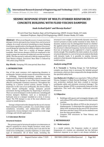
FVDwithbaseplateispickedhereforthemodellingofthe structuresinceitissimpletofit.Theclevis-baseplatelayout offluidviscousdampersandlock-upmechanismsisdepicted below.
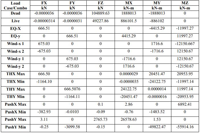
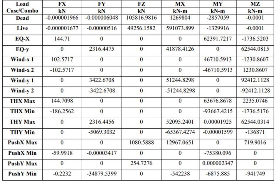
An estimate of the greatest lateral force that may be generated by seismic ground motion at the base of a structureisknownasbaseshear.
Table- 4 : Base Reactions of SBSC with FVD
Fig -1:Fluidviscousdampers&lock-updevicesclevis
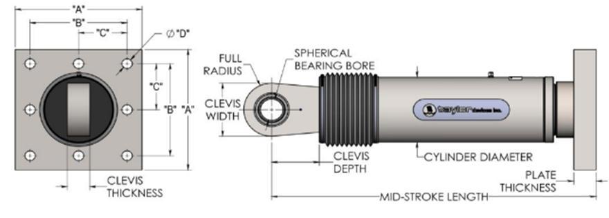
Responses when loaded in different directions
Table -3: Maximum PSA at Zero Damping
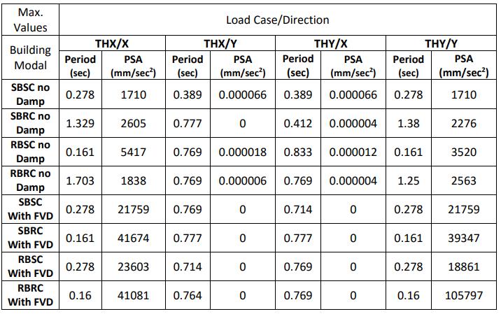
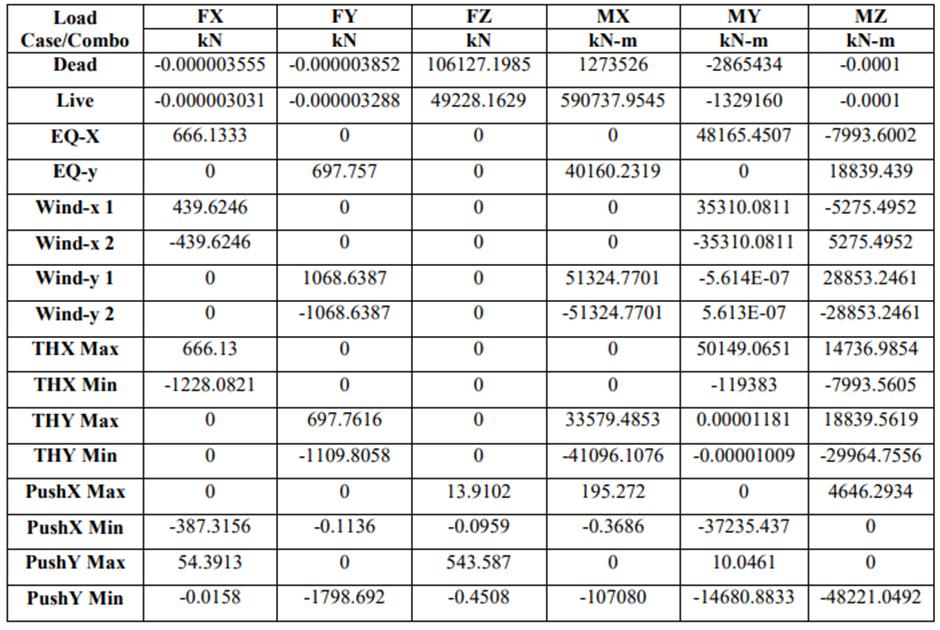
Table-5: Base Reactions of SBRC with FVD
International Research Journal of Engineering and Technology (IRJET) e-ISSN:2395-0056
Table-6: Base Reactions of RBSC with FVD
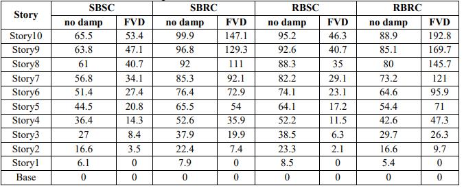
ETABS gives a simple table in the summary output with "StoryMaximumandAverageLateralDisplacements".This offers information of greatest to average ratio to assess torsionalirregularity.
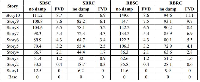
TheMaximumDisplacementsowingtoPush-XinX-direction are:
Table-8: Max. Disp. of Modals at different stories due to PushX
Table-7: Base Reactions of RBRC with FVD
TheMaximumDisplacementsduetoPush-YinY-direction are:
Table-9: Max. Disp. of Modals at different stories due to PushY
Volume: 09 Issue: 11 | Nov 2022 www.irjet.net p-ISSN:2395-0072 © 2022, IRJET | Impact Factor value: 7.529 | ISO 9001:2008 Certified Journal | Page564
An easy-to-read table containing "Storey Maximum and Average Lateral Displacements" was produced from the ETABS. To check for torsional irregularity, this offers an indicatorofthemaximumtoaverageratio
International Research Journal of Engineering and Technology (IRJET) e-ISSN:2395-0056
Volume: 09 Issue: 11 | Nov 2022 www.irjet.net p-ISSN:2395-0072
Fig -2: ComparisonMaximumstorydisplacementsdueto PUSHX
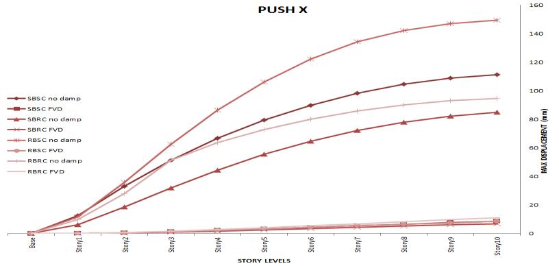
Fromtheinterrelationcurvesinfigure2,itisfoundthatdue toinsertionofFVDinthestructuresthedisplacementshave beenreducedby92.17%forSBSC,91.88%forSBRC,94.25% forRBSCand88.26%forRBRC.
From the comparison values in figure 4, it can be clearly foundthatduetointroductionofFVDinthestructuresthe baseshearshavebeendiminishby77%forSBSC,54.9%for SBRC,78.21%forRBSCand93.95%forRBRCinTH-X/Xdirection.Similarly,thebaseshearshavebeenreducedby 77% for SBSC, 63.87% for SBRC, 75.27% for RBSC and 28.5%forRBRCinTH-Y/Y-direction
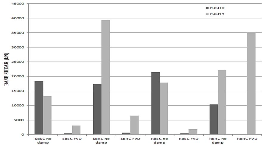
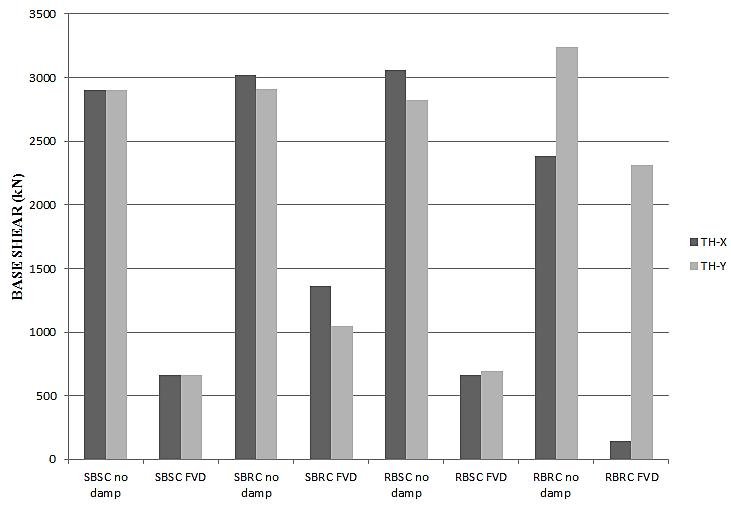
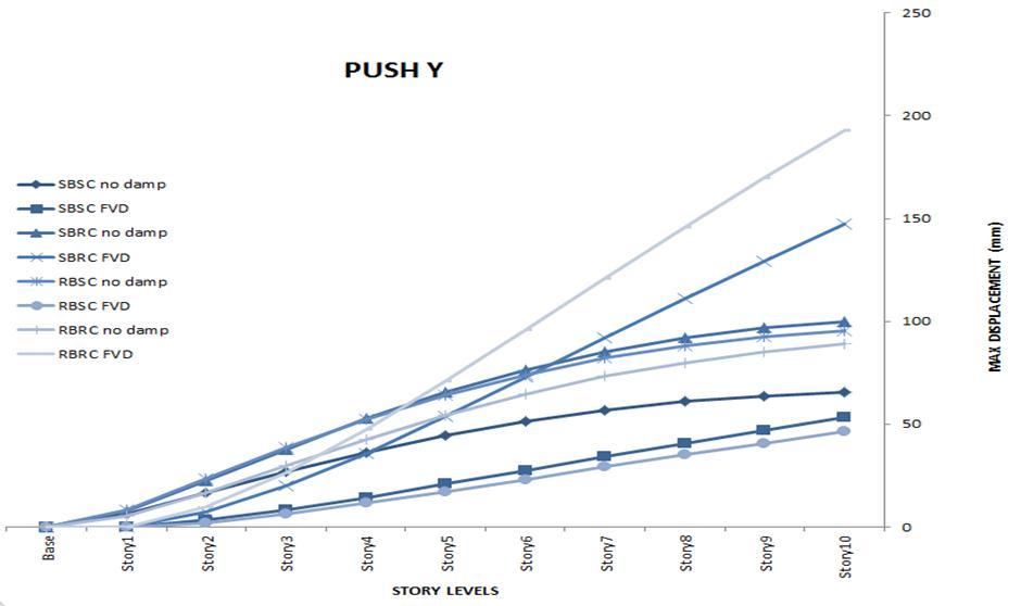
Fig -3: ComparisonMaximumstorydisplacementsdueto PUSHY.
From the comparison curves in figure 3, it can be clearly predicatedthatduetoinoculationofFVDinthestructures thedisplacementshavebeenreducedby18.4%forSBSCand 51.36% for RBSC. Whereas SBRC and RBRC doesn’t show any variation in this direction but overall structural displacementsarewithinlimitingvalues.
Fromthecorrelationvaluesinfigure4,itcanbeprecisely found that due to installation of FVD in the structures the baseshearshavebeenminiaturizedby97%forSBSC,96% forSBRC,98.19%forRBSCand99.4%forRBRCinPUSH-X/ X-direction. Correspondingly the base shears have been reducedby76.4%forSBSC,83.4%forSBRCand89.94%for RBSCinPUSH-Y/Y-direction.
International Research Journal of Engineering and Technology (IRJET) e-ISSN:2395-0056
Volume: 09 Issue: 11 | Nov 2022 www.irjet.net p-ISSN:2395-0072
Thefollowingconclusionsmaybeinferredfromthedataand analysis:
1. FVD can reduce the maximal PSA time period in responsespectrumcurvesbyupto90%.Inatimehistorystudy,FVD250reducedthestructures'Base Shearby70%.Themostimportantthingtoknow UseoftheFVDreducesdisplacementsby90%.
2. Regardless of the floor layout, square columns appeartoperformbetterthanrectangularcolumns intermsofstructuralreaction.
3. It is more difficult to assess damage to buildings usingpush-overanalysisthantimehistoryanalysis when analysing the seismic performance of structures.
1. FVD250willonlybeusedonconstructionswith outsidecornersforthesakeofthisthesis.
2. Modifying the same structures with FVD500 enablesthemtobeinstalledinthemiddleofthe exterior.
3. Thisworkmaybeextendedtoincludeirregular structures,unsymmetricalstructures,andtall structures
4. Itsapplicationtosteelstructurescanprovidea greatdealofpracticalsolutions.
5. K-shape and M-shape can be utilised in conjunctionwithFVD.
[1] M.R.Arefi,“Astudyonthedampingratiooftheviscous fluid dampers in the braced frames,” vol. 3, no. 4, pp. 1223–1235,2014.
[2] J.Marti,M.Crespo,andF.Martinez,“Seismic Isolation andProtectionSystems,”Seism.Isol.Prot.Syst.,vol.1, no.1,pp.125–140,2010.
[3] M.K.MuthukumarG,“Analyticalmodelingofdamping,” indianConcr.J.,vol.88,no.4,2014.
[4] I. López, J. M. Busturia, and H. Nijmeijer, “Energy dissipationofafrictiondamper,”J.SoundVib.,vol.278, no.3,pp.539–561,2004.
[5] J.A.InaudiandJ.M.Kelly,“MassDamperUsingFrictionDissipatingDevices,”J.odEng.Mech.,vol.121,no.1,pp. 142–149,1995.
[6] W. J. William H. Robinson, “Lead Damper for base isolution.pdf.”Proceedingsof9thworldconferenceon earthquake,1998.
[7] J.Otten,J.Luntz,D.Brei,K.A.Strom,A.L.Browne,andN. L.Johnson,“Proof-ofConceptoftheShapeMemoryAlloy ReseTtable Dual Chamber Lift Device for Pedestrian ProtectionwithTailorablePerformance,”J.Mech.Des., vol.135,no.6,p.61008,Apr.2013.
[8] D. Demetriou, N. Nikitas, and K. D. Tsavdaridis, “Semi active tuned mass dampers of buildings: A simple control option,” Am. J. Eng. Appl. Sci., vol. 8, no. 4, pp. 620–632,2015.
[9] E. L. Anderson, “Performance-Based Design of SeismicallyIsolatedBridges,”p.494,2003.
[10] S.Infanti,J.Robinson,andR.Smith,“ViscousDampers forHigh-RiseBuildings,”14thWorldConf.Earth.Eng., 2008.
[11] V. Umachagi, K. Venkataramana, G. R. Reddy, and R. Verma,“ApplicationsofDampersforVibrationControl ofStructures:AnOverview,”Int.J.Res.Eng.Technol.,pp. 6–11,2013.
[12] J.Marko,D.Thambiratnam,andN.Perera,“Influenceof dampingsystemsonbuilding90structuressubjectto seismiceffects,”Eng.Struct.,vol.26,no.13,pp.1939–1956,2004.
[13] V. S. Balkanlou, M. R. Bagerzadeh, B. B. Azar, and A. Behravesh,“EvaluatingEffectsofViscous Damperson optimizing Seismic Behavior of Structures,” no. 2007, 2013.
[14] A.Chopra,“Dynamicsofstructures,”2012.
[15] K.-H.Chang,StructuralAnalysis,vol.163.2009.
[16] Y.G.ZhaoandT.Ono,“Momentmethodsforstructural reliability,”Struct.Saf.,vol.23,no.1,pp.47–75,2001.
[17] M. Paz, “Structural Dynamics.pdf.” Van Nostrand ReinholdCompany,NYC.,p.574,1985.
[18] S.AmirandH.Jiaxin,“OptimumParameterofaViscous DamperforSeismicandWindVibration,”vol.8,no.2, pp.192–196,2014.
[19] Y.Zhou,X.Lu,D.Weng,andR.Zhang,“Apracticaldesign methodforreinforcedconcretestructureswithviscous dampers,”Eng.Struct.,vol.39,pp.187–198,2012.
International Research Journal of Engineering and Technology (IRJET) e-ISSN:2395-0056
[20] Ö. Atlayan, “Effect of Viscous Fluid Dampers on Steel MomentFrameDesignedforStrengthandHybridSteel MomentFrameDesign,”Environ.Eng.,2008.
[21] B. S. Taranath, Reinforced Concrete Design of Tall Buildings.
[22] LIYA MATHEW & C. PRABHA, “Effect of Fluid Viscous DampersinMultiStoreyedBuildings,”IMPACTInt.J.Res. Eng.Technol.(IMPACTIJRET),vol.2,no.9,pp.59–64, 2014.
[23] R.GettuandM.Santhanam,“Retrofitofnon-engineered buildings,”Handb.Seism.retrofitBuild.,no.April,p.471, 2007.
Volume: 09 Issue: 11 | Nov 2022 www.irjet.net p-ISSN:2395-0072 © 2022, IRJET | Impact Factor value: 7.529 | ISO 9001:2008 Certified Journal | Page567