International Research Journal of Engineering and Technology (IRJET) e-ISSN:2395-0056

Volume: 09 Issue: 11 | Nov 2022 www.irjet.net p-ISSN:2395-0072
International Research Journal of Engineering and Technology (IRJET) e-ISSN:2395-0056
Volume: 09 Issue: 11 | Nov 2022 www.irjet.net p-ISSN:2395-0072
1
, Prof. A.K.Battu2
1ME Mechanical Design Engineering student at DYCOE Akurdi ²Assistant Professor at DYCOE Akurdi ***
Abstract - Solar is a free source of energy found in nature, and most modern technologies, from vacuum cleaners to electric vehicles, are powered by it. Solar collectors are now being used to develop energy usage in both residential and industrial applications of water heating systems.Despitethe fact that solar water heaters come in a variety of configurations, they all use absorber tubes with a circular cross section. This study investigates the effects of different diameters and shapes of absorberplatetubes(zigzag,u-bent double parallel, etc.) on thermal performance. In the analysis, consistent area of cross section along flow channel and constant perimeter of tube flow path will be used as comparison criteria for different designs. This research allows us to create a prescription for the size and shape of various absorber tubes' cross sections.
Key Words: - Solar, Flat plate collector, Heat transfer & CFD.
Solarflatplatecollectorisadevicewhichaccumulate availablesunenergyorraysandtransfigureitintorequired usefulenergyusingwaterorairasworkingmedium.Solar flat plate collector has main two parts – metal plate , absorberplateandbesideswhichinternaltubingstructure, size and material of tube are main factors for improving efficiencyofsolarflatplatecollector.
Here,weusewaterasworkingmediumandbychanging tubestructure,sizeandmaterial weare tryingtocheck reliabilityandperformanceofSolarcollectorwiththehelp ofANSYSsoftware–CFDDomain comparewithphysical model.
Heat transfer is defined as the movement of thermal energy from one region of space to another. Conduction, convection, and radiation are the three primary ways of heattransport.ModelingConductiveandConvectiveHeat Transfer physical models containing simply conduction and/orconvectionarethesimplest,but buoyancy-driven flow or natural convection Natural Convection and Buoyancy-Driven Flows Theory, and radiation models ModelingRadiationaremorecomplicated.
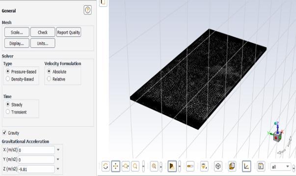
2.1.1 Procedure for Ansys Workbench CFD analysis
1.The first step in Ansys CFD model is to Import the geometry file, may be STP or IGS file from the created formatofsoftwarewillberequired.
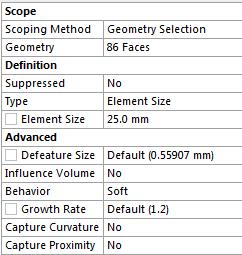
Figure3AnsysCFDmodule–Importationof geometryfile
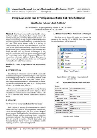
2.1.2 Mesh generation & named selection
Figure4meshmodule
International Research Journal of Engineering and Technology (IRJET) e-ISSN:2395-0056
Volume: 09 Issue: 11 | Nov 2022 www.irjet.net p-ISSN:2395-0072
Figure6nodesandelements

2.1.3 Setting up the problem to its boundary condition.
a. Aftermeshing&namedselection3rdprocessissetup, which means setting up the problem for defined boundary conditions.Thisprocesscontainsseveralscopeswhichneedsto be set up before solving it. following are the configuration or boundaryconditionappliedwhilesolving.
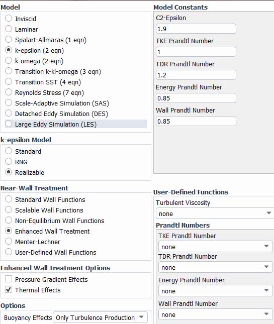
i. Checkingformesh
ii. Turningonenergyequation
iii. Describingtypeofflow
Figure8Viscosmodel
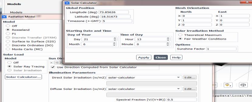
2.1.4 Radiation model
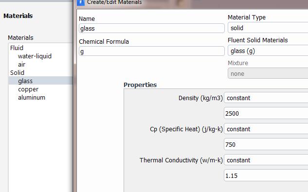
Figure9radiationmodel 2.1.5 Material Creation
Figure10material
International Research Journal of Engineering and Technology (IRJET) e-ISSN:2395-0056
Volume: 09 Issue: 11 | Nov 2022 www.irjet.net p-ISSN:2395-0072
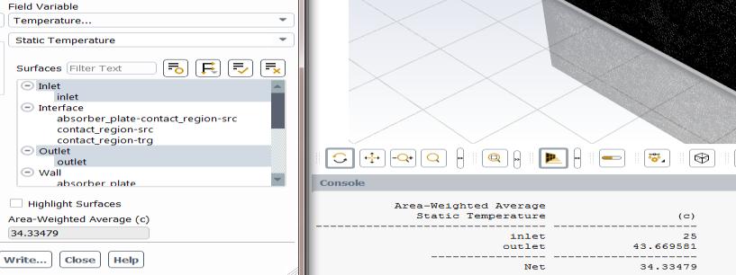
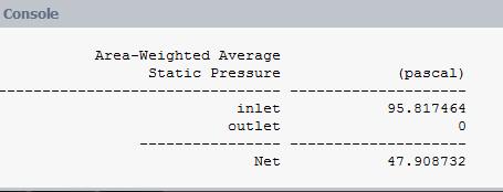
1. inlet=0.05kg/secmassflowinlet
2. inletwatertemperature=25degreeCelsius
3. absorber plate = copper material addition + solar tracingturningon
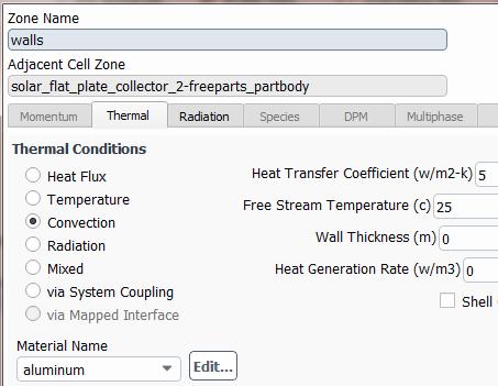
4. walls
Figure11wallscoping
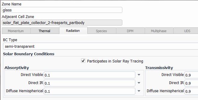
2.1.7 glass
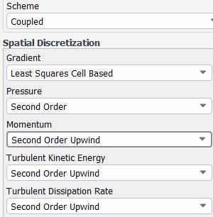
2.1.8 Method for solution
Figure13solutionType
viii.initialization–Hybridinitialization
ix.solutioncalculation50iterationorsteps.
2.1.9 Results
Velocityflowratioat0.05k/secinletflow
Figure14geometryinresultmode
Figure12glassscoping
International Research Journal of Engineering and Technology (IRJET) e-ISSN:2395-0056
Volume: 09 Issue: 11 | Nov 2022 www.irjet.net p-ISSN:2395-0072
Figure15resultinlet&outletvelocity
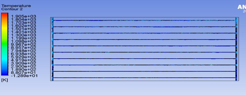
Figure19temperaturecontour
2.1.10 Discussion
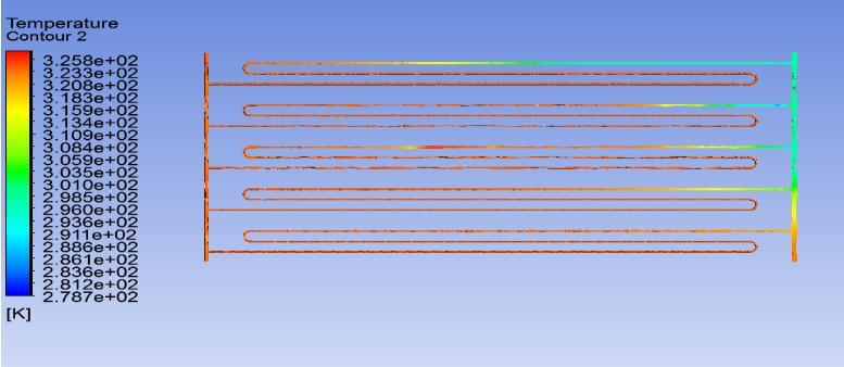
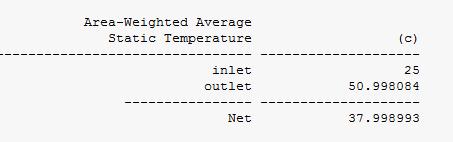
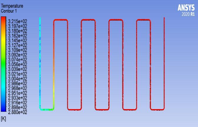
In this iteration parallel tube are considered and radiation is appliedontopoftheglass.Thewaterflowinginsidethetubehas a temperatureof 25degree Celsius andatoutlet43.66 degree Celsiushasbeenmeasured.
In next iteration we will calculate the outlet temperature by changingitspathfromparalleltoU-bent.

2.2 Iteration 2
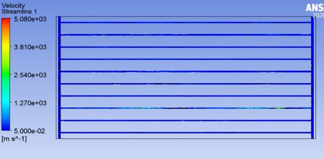
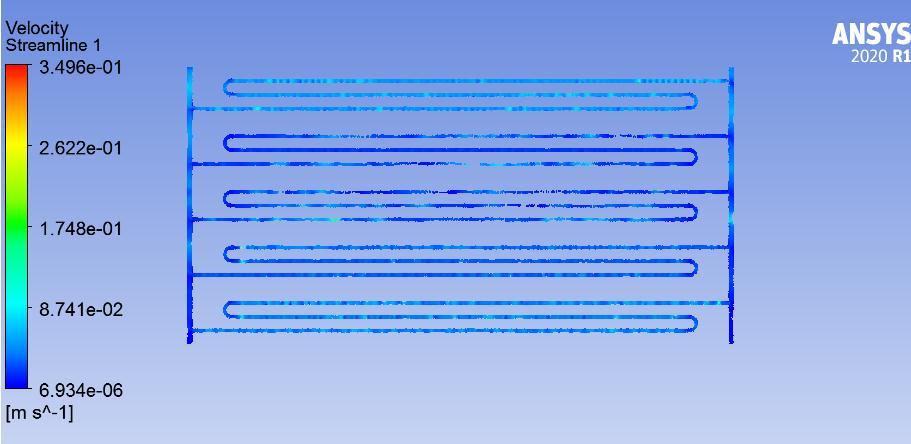
Figure16Velocity
2.2.1 In this iteration
1. boundaryconditions
2. materialconstants
3. solarmodule
4. energyequationsand
5. Numberofstepsiterations
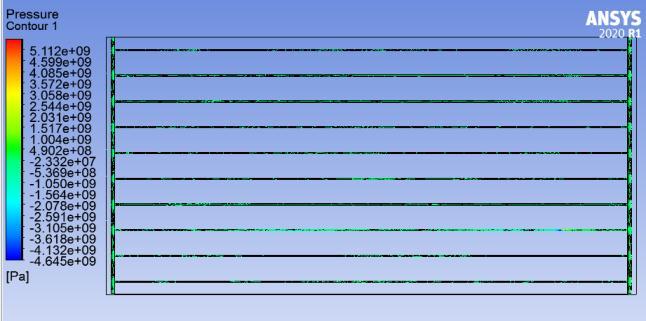
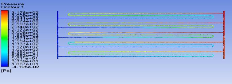
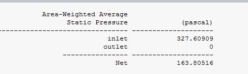
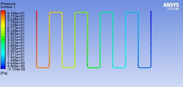
Figure17pressureinpascal
Havebeenkeptsameastothepreviousproblem
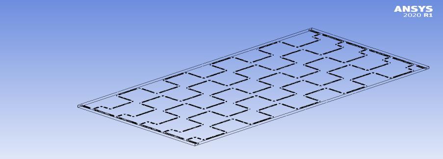
Onlytubepathhasbeenchangedfromstraightorparalleltoubent. Aswecanseeinthebelowfigure.
Figure18temperaturecontours
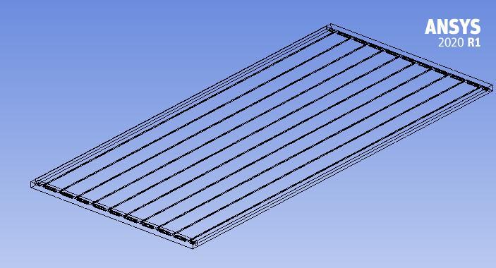
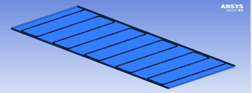
Figure20solarflatplatecollectorwithU-Benttubes
International Research Journal of Engineering and Technology (IRJET) e-ISSN:2395-0056 Volume: 09 Issue: 11 | Nov 2022 www.irjet.net p-ISSN:2395-0072
International Research Journal of Engineering and Technology (IRJET) e-ISSN:2395-0056
Volume: 09 Issue: 11 | Nov 2022 www.irjet.net p-ISSN:2395-0072
1. Velocity
2.4 Iteration 4
Figure28velocity
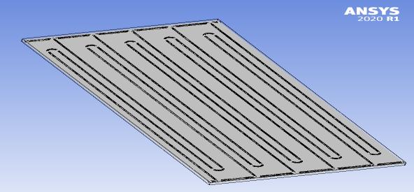
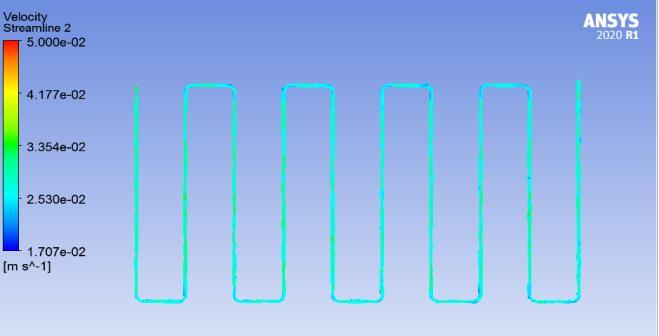
Figure32Zig-Zagwithsingletubing
• Gapbetweentubes = 200mm
• Nooftubes = 10X
1. Temperature Results.
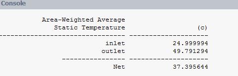
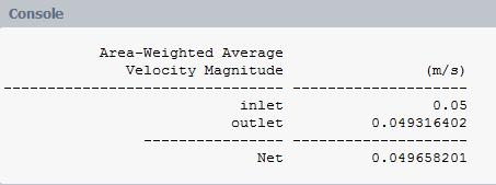
Figure29Velocitydistributioninthetubing
2. Pressure
Figure33temperatureresults
Figure30pressure
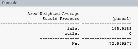
Figure34temperatureresultplotonsingletubeZig-zagPath
Figure31temperaturecontourofZig-Zagtubing
2022, IRJET | Impact Factor value: 7.529 | ISO 9001:2008 Certified
International Research Journal of Engineering and Technology (IRJET) e-ISSN:2395-0056
Volume: 09 Issue: 11 | Nov 2022 www.irjet.net p-ISSN:2395-0072
2. Pressure Results
• MaterialComparisonforexperimentalmodal
• Material
• Tube
SteelCollector
Copperalloy
Figure34Pressure
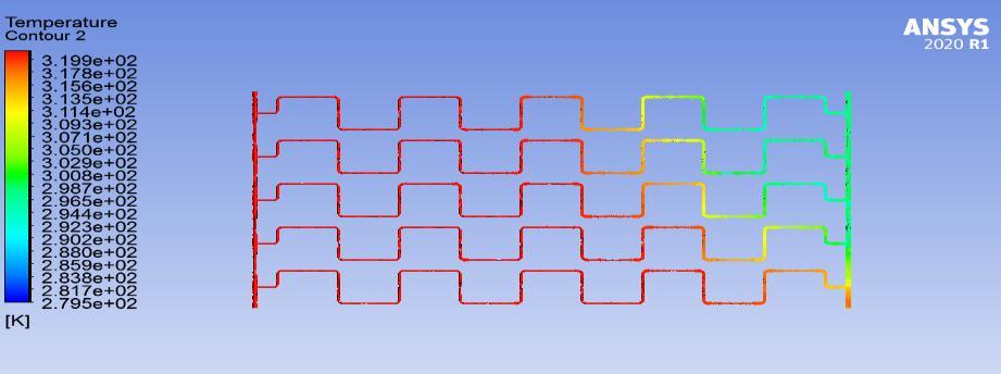
Figure38temperaturecontour
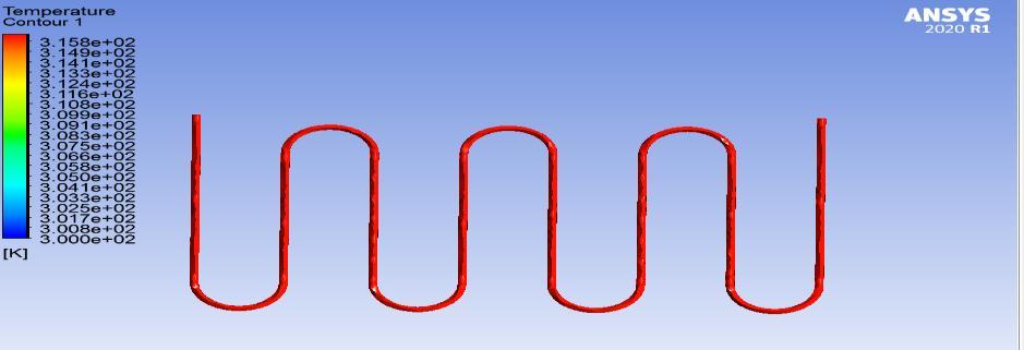
Figure35pressuredropatoutlet
3. Velocity
figure39temperature
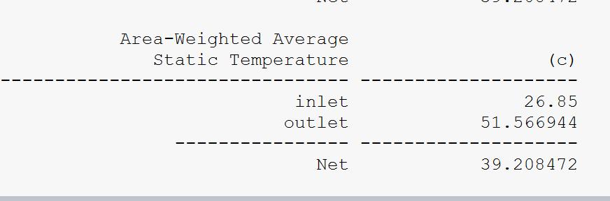
Figure36velocity
Figure40Pressure
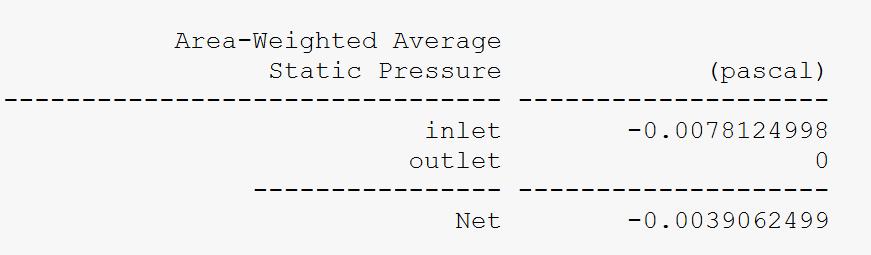
Figure37velocityvaluesatdefinedoutlet
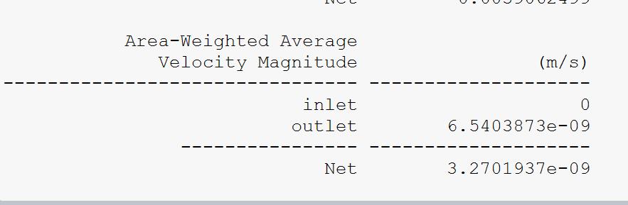
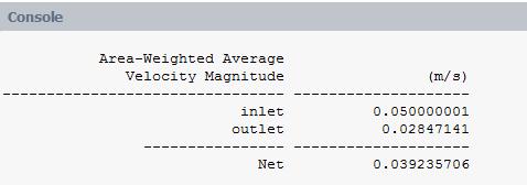
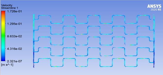
Figure41Velocity
International Research Journal of Engineering and Technology (IRJET) e-ISSN:2395-0056
Volume: 09 Issue: 11 | Nov 2022 www.irjet.net p-ISSN:2395-0072
LCD screen About35.7x16.8mm/1.4x0.66''
Wire length 1.5m/4.9ft
TableSpecificationoftemperaturesensor
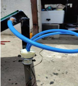
3.3 Water motor
Figure42ExperimentalModalSolarflatplatecollectorsingle coppertubewithsteelcollector&FigureWatermotor
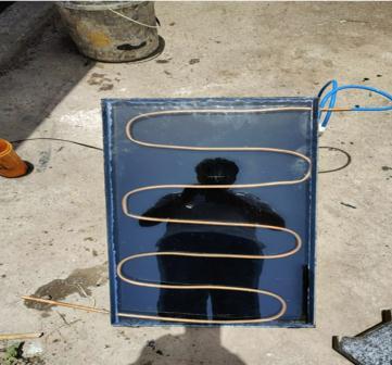
3.1 Parameters
Collector750*400*30mm
Glass750*400*2mm
Coppertubediameter = 10mm Watermotor = 6vpowers
Temperaturesensor Blackpaint = forabsorption
3.2 Digital result
Temperaturesensorisusedtomeasuretheoutletflowofthe waterflowinginsideasteelcollectorviacoppertube.
R3856-12VDCDiaphragmBasedMiniAquariumWater Pumpisanidealnonsubmersiblepumpforvarietyofliquid movement application. It has enough pressure to be used with nozzle to make spray system. The pump can handle heated liquids up to a temperature of 80°C and when suitablypoweredcansuckwaterthroughthetubefromup to2mandpumpwaterverticallyforupto3m.
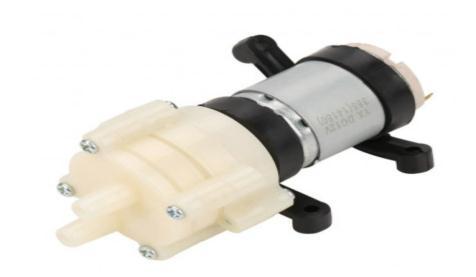
1. Model:R385
2. RatedVoltage:DC6Vto12V(1amps)
3. Workingcurrent:0.5Ato0.7A(Max)
4. Power:4W-7W
5. MaxLift:3m
6. MaxSuction:2m
7. MaxWaterTemp:80°C
8. PumpSize:90mm*40mm*35mmapprox.
9. Fluid:0-100°C
10. Input/outputtubediameter:outer8.5mm,inner6mm approx.
11. MaxCurrent:Upto2Ampswhilestartingup
12. Life:upto2500Hours
13. Themaximumflowrateofupto1–3L/min.
Figure43LCDtemperaturesensor
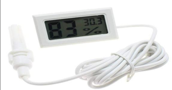
Weight 50g
Battery 2LR44buttonbatteries(Included)
Size About 48x28.5x15.2mm/1.88x1.12x0.59''
Figure44diaphragmMiniMotor
International Research Journal of Engineering and Technology (IRJET) e-ISSN:2395-0056
Volume: 09 Issue: 11 | Nov 2022 www.irjet.net p-ISSN:2395-0072
Outlettemperatureofwaterafter–minute
Figure45temperatureofwateratoutletafter75min
Experimental results in tabular form
Sr. No Time in hours Temperature T1 in 0C Temperature T2 in Degree Celsius
1. 55 min 24 0C 50.6 0C
2. 75min 24 0C 59.5 0C Software AnsysCFD
1. 50 Iterations 26.85 51.566 0C
Table1Analytical&experimentalanalysis
• Hencethevalueoftemperatureat55minmatchingthe simulationresultwhichwassolvedfor50iterations.
• Hencetheprojectisvalidatedaswecanseetheabove readingsobtainedarematchingwiththeexperimental solution.
• Thefabricatedparthasanefficiencytorisethewater with an average increment in the temperature radiationofsunenergy.

• Futurescope
• Onecanchangetubeandcollectormaterialtoknowthe thermalaspectofproperties.
Thisprojecthelpsindeterminingthedesignparameter requiredtoenhancethethermalheattransferbetween the flat plate solar collector and the working medium passinginsideacoppertube.

3D model was prepared using Catia v5 3D experience software, & FEA simulation is done using Ansys workbench.
UntilnowFEMfordifferentiterationshavebeensolved, basedonthedesigncriteria&resultswerenotedoutas wecanseeintheresulttabularcolumnforbelowpath flowoftubingsection.
• Paralleltubeflow
• U-benttubeflow
• Zig-zagwith5Xtubing&
• Zig-Zagwith1Xtubing
Zig-Zag with steel material process, temperature of waterbetterthananyotherpath,becauseofzig-zaglike structure, water inside the tube rests longer than any othercross-section,butonlydisadvantageispressure.
Hencefromallaspect
Steelisbetterinstrength,asitpossessesgoodthermal& electricalenergy,lowerincost.Collectorwillbemade usingSS.Tubecopperandathermalglasswithabsorber plate.
To validate the project, experimental modal will be prepared by procuring standard materials and fabricationprocessandwillbevalidatedwiththeFem solution
International Research Journal of Engineering and Technology (IRJET) e-ISSN:2395-0056
Type Boundary Conditions
1. Parallel tube
2. U-Bent tube
Inlettemperature
Result Result: Temperature In 0c
Pressure Outletin
3. Zig-zag
Outlet Velocity 0.05m/sec
T1=250C
Inlettemperature
T1=250C
P1=418 temperature T2=43.660C
Outlet Velocity 0.05m/sec
Inlettemperature 5Xtube
4. Zig-zag
T1=250C
Inlettemperature 1Xtube
5. Zig-Zag with steel collector
Outlet Velocity 0.05m/sec
InM/Sec
Result Velocity Pascal
V2=33.635 P2=0
P1=327.6 temperature T2=50.990C
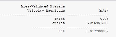
V2=0.0454 P2=0
P1=145 temperature T2=48.98 0C
V2=0.0493 P2=0
Sr.No Components Specs Cost
1. WaterMotor 1X 6V 345/-
2. Coppertube 1x 1meter 785/-
3. Collector Double angleplate 1meter
345/-
4. Sheetplates 1-2mm thickness 645/-
5. Transparent tube 1meter 165/-
6. Glass 2mm thickness 1200/-
7. Temperature Sensor 1X 263/Components Total 3748/Fabrication& transportation 3500/Total 6748/-
Outlet temperature Velocity 0.05m/sec
T1=250C
P1=95 T2=49.79 0C
V2=0.0284 P2=0
T2=51.566oC P10 T1=250C
V2= 2.481e8 P2=-0.078
Table2Billofmaterial
[1] "Solar Energy Perspectives: Executive Summary". InternationalEnergyAgency.2011.Archivedfromthe original(PDF)on3December2011.
[2]Jumpup^"Energy".rsc.org.
Table3resultstable
Hencetheanalysisdoneforexperimentmodal has a temperature of 51.566944 degree Celsiusat50SubIteration.
In next phase, modal of solar flat plate collector will be prepared with additive manufacturingProcess.
Volume: 09 Issue: 11 | Nov 2022 www.irjet.net p-ISSN:2395-0072 © 2022, IRJET | Impact Factor value: 7.529 | ISO 9001:2008 Certified Journal | Page502
[3] International Journal of Emerging Technology and AdvancedEngineeringWebsite:www.ijetae.com(ISSN 2250-2459,ISO9001:2008CertifiedJournal,Volume3, [4] U.S. Department of Energy - Energy Efficiency and RenewableEnergySolarEnergyTechnologiesProgram. http://www1.eere.energy.gov/solar
[5] “Handbook of Heat Transfer” by Warren M.Rohsenow,JamesP.Hartnett,YoungI.Cho,MCGRAWHILL,3rdEdition,ISBN0-07-053555-8.
[6]MohammedAbdulJunaid&S.IrfanSadaq“Design& OptimizationofFinsinSolarFlatPlateCollectorUsing CFD”. International Journal of Science & Research Website:www.ijsr.net(ISSN2319-7064)Volume6Issue 1,January2017
International Research Journal of Engineering and Technology (IRJET) e-ISSN:2395-0056 Volume: 09 Issue: 11 | Nov 2022 www.irjet.net p-ISSN:2395-0072
[7]SatelliteImageofLocation,www.google.com/map
[8] https://www.internationaljournalssrg.org/IJME/paper -details?Id=313
[9] C. Eaton and H. A. Blum, “The use of moderate vacuum environments as a means of increasing the collection efficienciesandoperating temperatures of flat-platesolarcollectors,”SolarEnergy,vol.17,no.3, pp.151–158,1975.
[10] N. Benz and T. Beikircher, “High efficiency evacuatedflatplatesolarcollectorforprocesssteam production,”SolarEnergy,vol.65,no.2,pp.111–118, 1999.
[11]C.Benvenuti,“Evacuableflatpanelsolarcollector,” PCT/EP2004/000503,CERN,2005.
[12]R.MossandS.Shire,“Designandperformanceof evacuated solar collector microchannel plates,” in EuroSunConference,Aix-les-Bains,France,2014.
[13]G.S.F.Shire,R.W.Moss,P.Henshall,F.Arya,P.C. Eames,andT.Hyde,“Developmentofanefficientlowand medium temperature vacuum flat-plate solar thermalcollector,”inRenewableEnergyintheService ofMankind,vol.2,pp.859–866,SpringerInternational Publishing,Switzerland,2016.
[14]Y.Fang,T.Hyde,P.C.Eames,P.C.Eames,andN. Hewitt, “Theoretical and experiment analysis of the vacuum pressure in a vacuum glazing after extreme thermalcycling,”SolarEnergy,vol.83,no.9,pp.1723–1730,2009.
[15] M. M. Koebel, H. Manz, K. E. Mayerhofer, and B. Keller, “Service-life limitations in vacuum glazing: a transient pressure balance model,” Solar Energy MaterialsandSolarCells,vol.94,no.6,pp.1015–1024, 2010
Mr.VipulSudhirMahajan

MEMechanicalDesignEngineering studentfromDYCOEAkurdi.
2022, IRJET | Impact Factor value: 7.529 | ISO 9001:2008 Certified Journal | Page503