International Research Journal of Engineering and Technology (IRJET) e-ISSN:2395-0056
Volume: 09 Issue: 11 | Nov 2022 www.irjet.net p-ISSN:2395-0072

International Research Journal of Engineering and Technology (IRJET) e-ISSN:2395-0056
Volume: 09 Issue: 11 | Nov 2022 www.irjet.net p-ISSN:2395-0072
1
1PG Student, Department of Electrical Engineering, Government College of Engineering, Amravati-444604, India ***
ABSTRACT -: The renewable energy sources play an important role in electric power generation with growing environmentalconcerns.Powerelectronicsconvertersareusedtoconnectrenewableenergysourcesinordertoimprove power quality at the point of common coupling (PCC). So, in this paper, we reviewed power quality issues and their underlyingcauses,aswellasSTATCOM,whichcanmeetallofthesedemandsforvoltagesagandswellcompensations.A controller unit based on a modified Icos algorithm is proposed for STATCOM, which performs reactive power compensation and power factor correction while also providing real power support from renewable energy sources via STATCOM.
Keyword: Solar photovoltaic, Wind energy, Hybrid PV-Wind system, STATCOM, Voltage stability.
With the nonstop need for safe, dependable and quality electricity force, more protean styles of power generation are being enforced world-wide. Two technically grueling generalities to achieve the over statedthingarestatedthen.originally,renewableenergy sourcesaremadeuseof,duetotherisingproblemswith the conventional reactionary energies and environmental factors. Secondly,a custompowerdevice similar as STATCOM is used as an interfacing unit between grid, cargo and renewable energy source. The renewable energy source and STATCOM unit are driven by a simple algorithm called modified Icosφ algorithm, which provides the necessary reactive power compensation, power factor correction and also control of real power inflow from the source( grid) and renewableenergy.
The theme of the paper is to ameliorate the power quality of force in locales where electric grids are weak orsensitiveloadsneedtobedefendedagainstproblems similar as low power factor, voltage regulation, and reactivepowercompensation.Thispaperalsocompares the performance of proposed modified Icosφ algorithm withthemodifiedIRPTalgorithmforSTATCOMcontrol.
The STATCOM is a power electronics device grounded on the principle of injection or immersion of reactive current at the point of common coupling(PCC) to the power network.The mainadvantage oftheSTATCOM is that the compensating current doesn't depend on the voltage position of the PCC and therefore the compensatingcurrentisn'tloweredasthevoltagedrops TheotherreasonsforpreferringaSTATCOMratherofan SVCareoverallsuperiorfunctionalcharacteristics,faster performance, lower size, cost reduction and the
capability to give both active and reactive power, thereby furnishing flexible voltage control for power qualityenhancement.
When a renewable energy source is used with power electronic interface, the need for the operation of fresh transformers and power exertion outfit’s arises. The downsides of using these fresh circuits are high switching loss, increased costs and a largish system; hence the proposed scheme replaces the need for fresh transformerswithaSTATCOMunit.
The STATCOM unit is intended for reactive power compensation as demanded by the cargo; the STATCOM unit is an inverter with DC link capacitor which gets its control beats from a regulator circuit. The control beats are generated using modified Icosφ algorithm, which in turncausestheSTATCOMtogivetherealpowersupport from the renewable energy source and reactive power compensationasandwhenneededbythecargo.
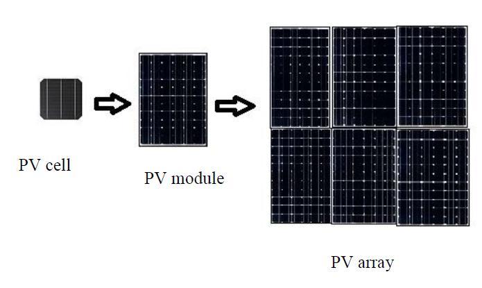
NumberofPVcellsareneededtoproducehighpowerin solar power generation system so for advanced power demand they're connected in series or in parallel for conformation of Solar Module or Solar panel and also formArray.
AgroupofPVcellsareinseriesconnectiontoformsolar panel or module. A photovoltaic module is a methodical arrangementofseriesconnectedPVcells.
A group of solar panels or modules connected together electrically in series and resemblant structure to form
© 2022, IRJET | Impact Factor value: 7.529 | ISO 9001:2008 Certified Journal | Page480

International Research Journal of Engineering and Technology (IRJET) e-ISSN:2395-0056
Volume: 09 Issue: 11 | Nov 2022 www.irjet.net p-ISSN:2395-0072
solararrayandthissolararrayisresponsibletoproduce advancedquantumofpower.
The following figure 1 shows the conformation of solar modelandsolararray.
voltage drops. As a result, the resulting decrease in efficiency can be offset by lowering series resistance in PV cell applications. Power losses in PV cells are caused by low shunt resistance, which provides an alternate current path for the light-generated current. As a result of such a diversion, the amount of current flowing through the PV cell junction decreases, as does the voltagefromthesolarcell.Figure2depictstheuseofthe nodeequation.
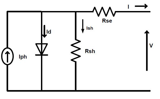
I=Iph- Id- Ish (1)
I=Iph–Isat(exp(q(V+I*Rse/aKT))-1)(V+I*Rse/Rsh)
IndividualPVcellsmustbemodelledinordertomodela PV array. These PV cells are combined to form the PV array that is used in the MPPT technique. The physical appearance and mechanism of a solar cell are used to create an equivalent electrical circuit. Generally, two circuits are accepted as equivalent electrical circuits of solar cells: one is a simplified model of a single diode solar cell and the other is a circuit with two diodes, one for reflecting diffusion and the other for carrier. The equivalentcircuitofa single diodesolarcell isshownin Figure2.
The main effect of series resistance is to lower the fill factor, and extremely high values may also lower the short-circuit current. When Rse is very high, the MPP
(2)
Where,‘a’istheidealityfactoranditsvalueisbetween 1and2.
36 solar cells having 9 modules (85 watt each) are connectedinseriesandresemblantconnectiontoforma PV array with 1000 w/ m ² insulation using MATLAB/ SIMULINK.
3.WindSystem
3.1BasicofWindSystem
Windpoweristheconversionprocessofkineticenergy fromwindintofurtherusefulformssimilaraselectricity byusingwindturbines.utmostultramodernwindpower is generated in the form of electricity by converting the gyration of turbine blades into electrical current by meansofanelectricalcreator.Inwindmills(amuchaged technology), wind energy is used to turn mechanical ministry to do physical work, similar as pumping water. Wind power is used in large scale wind granges for public electrical grids as well as in small individual turbines for furnishing electricity to pastoral places or grid- insulated locales like in Sweden. Wind energy is generous,renewable,extensivelydistributed,cleans,and reduces poisonous atmospheric and hothouse gas emigrations if used to replace reactionary- energydeducedelectricity.
Allwindsystemscorrespondofawindturbine,apalace, wiring, and the “balance of system ” factors regulators, inverters, and or batteries. Home wind turbines correspond of a rotor, a creator mounted on a frame, and(generally) a tail. Through the spinning of turbine blades,therotorcapturesthekineticenergyofthewind and converts it into rotary stir to drive the creator. Rotors can have two or three blades and the common wind system is using three blades type. The stylish suggestion of how important energy a turbine will produce is the periphery of the rotor, which determines
International Research Journal of Engineering and Technology (IRJET)
e-ISSN:2395-0056
Volume: 09 Issue: 11 | Nov 2022 www.irjet.net p-ISSN:2395-0072
its “ swept area, ” or the volume of wind cut by the turbine. The frame is the strong central axis bar onto which the rotor, creator, and tail are attached. The tail keepstheturbinefacingintothewind.
Allwindsystemscorrespondofawindturbine,apalace, wiring, and the “ balance of system ” factors regulators, inverters, and or batteries. Home wind turbines correspond of a rotor, a creator mounted on a frame, and( generally) a tail. Through the spinning of turbine blades,therotorcapturesthekineticenergyofthewind and converts it into rotary stir to drive the creator. Rotors can have two or three blades and the common wind system is using three blades type. The stylish suggestion of how important energy a turbine will produce is the periphery of the rotor, which determines its “ swept area, ” or the volume of wind cut by the turbine. The frame is the strong central axis bar onto which the rotor, creator, and tail are attached. The tail keeps the turbine facing into the wind power is the conversion process of kinetic energy from wind into further useful forms similar as electricity by using wind turbines. utmost ultramodern wind power is generated in the form of electricity by converting the gyration of turbine blades into electrical current by means of an electrical creator. In windmills( a much aged technology), wind energy is used to turn mechanical ministry to do physical work, similar as pumping water. Wind power is used in large scale wind granges for public electrical grids as well as in small individual turbines for furnishing electricity to pastoral places or grid- insulated locales like in Sweden. Wind energy is generous,renewable,extensivelydistributed,cleans,and reduces poisonous atmospheric and hothouse gas emigrations if used to replace reactionary- energydeduced electricity. All wind systems correspond of a wind turbine, a palace, wiring, and the “balance of system ” factors regulators, inverters, and or batteries. Home wind turbines correspond of a rotor, a creator mounted on a frame, and( generally) a tail. Through the spinningofturbineblades,therotorcapturesthekinetic energy of the wind and converts it into rotary stir to drive the creator. Rotors can have two or three blades andthecommonwindsystemisusingthreebladestype. The stylish suggestion of how important energy a turbinewillproduceistheperipheryoftherotor,which determines its “swept area, ” or the volume of wind cut by the turbine. The frame is the strong central axis bar onto which the rotor, creator, and tail are attached. The tailkeepstheturbinefacingintothewind.
Allwindsystemscorrespondofawindturbine,apalace, wiring, and the “balance of system” factors regulators, inverters, and or batteries. Home wind turbines correspond of a rotor, a creator mounted on a frame, and(generally) a tail. Through the spinning of turbine
blades,therotorcapturesthekineticenergyofthewind and converts it into rotary stir to drive the creator. Rotors can have two or three blades and the common wind system is using three blades type. The stylish suggestion of how important energy a turbine will produce is the periphery of the rotor, which determines its “ swept area, ” or the volume of wind cut by the turbine. The frame is the strong central axis bar onto which the rotor, creator, and tail are attached. The tail keepstheturbinefacingintothewind
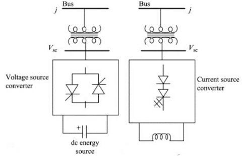
Figure. 3 Basic structure of STATCOM
STATCOM's basic structure is depicted in Figure 3. A Static synchronous Compensator (STATCOM) is a fastacting device that can provide or absorb reactive current, thereby regulating the voltage at the point of connectiontoapowergrid.Itfallsunderthecategoryof Flexible AC transmission system (FACTS) devices. The technology is built around a voltage source converter (VSC) with semiconductor valves in a multi-level modular configuration. The dynamic reactive current output range is symmetrical (under normal disturbed network conditions), but non-symmetrical designs are possible by incorporating mechanically or thyristor switchedshuntelementswithunifiedcontrolsystemsto cover the majority of conventional applications. The STATCOM design and quick response make the technology very useful for maintaining voltage during network faults (because STATCOMs can provide fast fault current injection limited to the rated current), enhancingshort-termvoltagestability.STATCOMscould also provide power factor correction, reactive power control, damping of low-frequency power oscillations (typically via reactive power modulation), active harmonic filtering, flicker mitigation, and power quality enhancements. Typical applications include electric power transmission, distribution, heavy industrial plant electrical networks, arc furnaces, high-speed railway
International Research Journal of Engineering and Technology (IRJET) e-ISSN:2395-0056
Volume: 09 Issue: 11 | Nov 2022 www.irjet.net p-ISSN:2395-0072
systems, and other electric systems where voltage stabilityandpowerqualityarecritical.
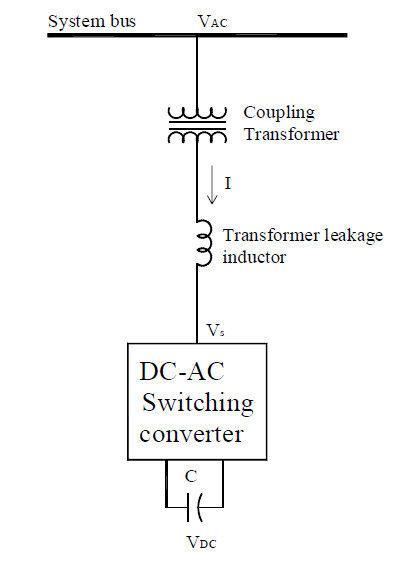
Figure. 4 Basic Configuration of STATCOM
Figure 4 depicts the fundamental configuration of STATCOM. A typical STATCOM configuration includes IGBT-based multi-level VSC, phase reactors, and a stepup transformer. It is grid-connected via shunt. A controlled internal voltage waveform is used to provide or absorb reactive current. The majority of STATCOMs onthemarkettodayoperateasgridfollowingconverters and require a grid voltage reference to function (with a defined level of grid strength). The response of the voltage waveform is adjusted in relation to the grid connectionpointvoltage.In general,STATCOMs operate as AC current controlled devices, though control of the output current is accomplished through amplitude regulation of the STATCOM internal voltage (behind the phase reactor), with the angle close to 90 degrees with
respect to the grid connection point voltage. Capacitive reactive power is provided to the grid if the STATCOM voltage amplitude is greater than the system voltage amplitude. If current flows from the system to the STATCOM in the opposite direction, inductive reactive power is provided. The amount of reactive current is limited by the thermal limits of the IGBTs and is determined by the transformer short circuit reactance and voltage difference. When the system voltage is within certain limits, both voltage amplitudes are equal, and no reactive power is exchanged with the grid, the systemisoperatingnormally.Ifthegridvoltageexceeds a certain threshold, STATCOM control will reduce the amplitude of the STATCOM voltage waveform, causing theSTATCOMtoactasaninductiveelementandabsorb reactive power from the grid. When the grid voltage exceedsacertainthreshold,themagnitudeofthevoltage waveform increases, causing the STATCOM to act as a capacitive element and supply reactive current to the grid.
•Seriescontrollersareusedtocontrolcurrentorpower flowaswellasdampenoscillations.
• Given MVA size, series controllers are several times morepowerfulthanshuntcontrollers.
•Shunt controllers are current sources that can draw or injectcurrentintoaline.Tolearnmore
•Shuntcontrollersarepreferredformanagingvoltageat andnearthepointofconnectionbecausetheyeffectively regulate voltage and dampen voltage oscillation. These controllers inject reactive currents that are either leadingorlagging,orbothactiveandreactivecurrents.
•Shuntcontrollersservicethebusnoderegardlessofthe linesconnectedtoit.
International Research Journal of Engineering and Technology (IRJET) e-ISSN:2395-0056
Volume: 09 Issue: 11 | Nov 2022 www.irjet.net p-ISSN:2395-0072
In this paper, the detailed comprehensive performance analysis of Wind Photovoltaic mongrel energy systeminter-connected to the grid via power- electronic interfacing were shown. To gain a more practical script, variable AC cargo is employed in the system along with intermittentpowersources ofsolarPVandWECsystem in an attempt to introduce severe dynamics into the mongrel system. This basically drives a necessity for a source of variable reactive power so as to maintain a voltage profile at the cargo machine. In these circumstances,STATCOMisimagedtobeachoiceofthe deviceasthesamehasbeenvindicatedtoamelioratethe voltage regulation in insulated mongrel systems as suggestedbyseveralstudies.
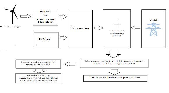
Figure5 showsthe block illustration of methodology to ameliorate the power quality issue similar as voltage slack and swell of wind- solar mongrel power system. The affair of solar PV array are given to the DC to DC motor for boosting purpose and the affair of wind turbine is given to the PMSG to induce the AC force, afterword it given to the Rectifier to convert it into DC becauseaffairofsolarisDC.Theaffairofboth(windand Solar) are given to the 3 phase Inverter which is grounded on set of firing angle which initiated by direct axis and quadrature axis factors of cargo current and reference current comparisons. That affair power of Inverter is also fed to the coupling motor for synchronization with power system. Coupling motor is coupling the power system and main AC grid transmissionlines.
This study provides a complete review of the methodology to ameliorate the power quality issues of the solar and wind mongrel system. The complete study of Solar and wind system were bandied collectively. The Wind and Solar mongrel system uses a STATCOM grounded regulator to enhance the system's power quality. This study shows the introductory idea that how well the STATCOM bettered voltage regulation and the responsibility of similar systems. Its effectiveness in each case state is estimated using both the dynamic terrain and flash responses. A tubular comparison study on the variety of different Data regulator bias. From the comparison table it shows that the STATCOM is a much better and further suitable for perfecting the systems power quality issues. Also, STATCOM mitigates the actuality of fresh reactive power inflow on the road and suppresses its negative goods, allowing the voltage profile to be successfully maintained. therefore, it's shown that STATCOM is necessary for the mongrel system to operate in grid integrated mode in order to indeed modestly increase system performance and STATCOM can stabilize the voltage at the connecting machine by conforming reactive power and might give the serviceability with a astounding response if these systems serve as anticipated and are held responsible. This approach only took into consideration direct stacks that were precisely still, theseheapsareuncommonin powernetworks.Nonlinear and inductive motor stacks make up the maturity of wise stacks, and any system disturbances like harmonious injections and current unbalance are added. unborn studies may indeed incorporate the integration of similar intelligent piles into a mongrel grid- integrated RES terrain to exploration the goods on system dynamics and probetheeventualityfordifferentDataregulatorsto perform a variety of tasks against harmonics and currentimbalance.
[1] Khare V, Nema S, Baredar P. Solar-wind hybrid renewable energy system: a review. Renewable Sustainable Energy Rev 2016;58:23–33. https://doi.org/10.1016/j.rser.2015.12.223.
[2] Jamil B, Siddiqui AT, Akhtar N. Estimation of solar radiation and optimum tilt angles for south-facing surfaces in Humid Subtropical Climatic Region of India. Eng Sci Technol an Int J 2016;19:1826–35. https://doi.org/10.1016/j.jestch.2016.10.004.
International Research Journal of Engineering and Technology (IRJET) e-ISSN:2395-0056
Volume: 09 Issue: 11 | Nov 2022 www.irjet.net p-ISSN:2395-0072
[3] GandomanFH,AhmadiA,SharafAM,SianoP,PouJ, HredzakB,etal.ReviewofFACTStechnologiesand applications for power quality in smart grids with renew- able energy systems. Renewable Sustainable Energy Rev 2018;82:502–14. https:// doi.org/10.1016/j.rser.2017.09.062.
[4] Jamil E, Qurratulain, Hameed S. STATCOM-based voltage regulation in grid in- tegrated wind farm under variable loading conditions. 2017 14th IEEE India Counc. Int. Conf. 2017. p. 1–6. https://doi.org/10.1109/INDICON.2017.8488062.
[5] Sinha S, Chandel SS. Improving the reliability of photovoltaic-based hybrid power system with battery storage in low wind locations. Sustainable EnergyTechnolAssess2017;19:146–59.
[6] Maatallah T, Ghodhbane N, Ben Nasrallah S. Assessment viability for hybrid energy system (PV/wind/diesel)withstorageinthenorthernmost city in Africa, Bizerte, Tunisia. Renewable Sustainble Energy Rev 2016;59:1639–52. https://doi.org/10.
[7] Phap VM, Yamamura N, Ishida M, Hirai J, Nga NT. Designofnovel grid-tiedsolar- windhybridpower plant using photovoltaic cell emulating system. 2016IEEEIntConf.Sustain.EnergyTechnol.2016. p.186–9.https://doi.org/10.1109/ICSET.
[8] harma B, Dahiya R, Nakka J. Effective grid connectedpowerinjectionschemeusingmultilevel inverter based hybrid wind solar energy conversion system. Electr Power Syst Res 2019;171:1–14.
[9] Bailek N, Bouchouicha K, Aoun N, EL-Shimy M, Jamil B, Mostafaeipour A. Optimized fixed tilt for incidentsolarenergymaximization onflatsurfaces located in the Algerian Big South. Sustainable EnergyTechnolAssess2018;28:96–102.
[10] Khan MJ, Yadav AK, Mathew L. Techno economic feasibilityanalysisofdifferentcombinationsofPVWind-Diesel-Battery hybrid system for telecommunicationap-plicationsindifferentcities of Punjab, India. Renewable Sustainable Energy Rev2017;76:577–607.
[11] Rini TH, Razzak MA. Voltage and power regulation in a solar-wind hybrid energy system. 2015 IEEE Int. WIE Conf. Electr. Comput. Eng. 2015. p. 231–4. https://doi. org/10.1109/WIECONECE.2015.7443904.
[12] Wang L, Lin T. Stability and performance of an autonomous hybrid wind-PV-battery system. 2007 Int. Conf Intell. Syst. Appl. to Power Syst. 2007. p. 1–6.https://doi.org/10.1109/ISAP.2007.4441622.
[13] Olamaei J, Ebrahimi S, Moghassemi A. Compensation of voltage sag caused by partial shading in grid-connected PV system through the three-level SVM inverter. Sustainable Energy Technol Assess 2016;18:107–18. https://doi.org/10.1016/j.seta.2016.10.001.
[14] IEA. Global energy demand rose by 2.3% in 2018, its fastest pace in the last decade. International Energy Agency (IEA), < https://www.iea.org/newsroom/news/ 2019/march/global-energy-demand-rose-by-23in-2018-its-fastest-pace-in-the-last-decade.html>; 2019n.d. https://doi.org/10.1016/j.seta.2017.05.004
[15] Hingorani NG, Gyugyi L. Understanding FACTS: Concepts and Technology of Flexible AC Transmission Systems. New York, NY: USA WileyIEEEPress;2000.p.1–6.
[16] MohammadpourHA,GhaderiA,MohammadpourH, Ali MH. Low voltage ride- through enhancement of fixed-speed wind farms using series FACTS controllers. Sustainable Energy Technol Assess 2015;9:12–21. https://doi.org/10.1016/j.seta. 2014.10.007.
[17] BasaranK,CetinNS,BorekciS.Energymanagement for on-grid and off-grid wind/ PV and battery hybrid systems. IET Renewable Power Gener 2017;11:642–9. https://doi.org/10.1049/ietrpg.2016.0545
[18] Jamil E, Ahmad S, Khan MH, Afzal M. Dynamic modeling of regulated solar PV- wind hybrid system for off-grid applications. 2017 Int Conf Energy, Commun Data Anal Soft Comput. 2017. p. 3221–6.
[19] PhilipJ,JainC,KantK,SinghB,MishraS,ChandraA, etal.Control andim- plementationofa standalone solar photovoltaic hybrid system. IEEE Trans Ind Appl
[20] SakthivelS.andMaryD.andVetrivelR.andKannan V. Senthaman(2011) “Optimal Location of SVC for Voltage Stability Enhancement under Contingency Condition through PSO Algorithm”, International Journal of Computer Application, Vol. – 20 No. – 1 PageNo.–30–36,2011.
International Research Journal of Engineering and Technology (IRJET) e-ISSN:2395-0056
Volume: 09 Issue: 11 | Nov 2022 www.irjet.net p-ISSN:2395-0072
[21] Baghaee H.R. and Jannati M. and Vahidi B. and Hosseininan S.H. and Rastegar H. “Improvement of Voltage Stability and Reduce Power System Losses by Optimal GA based Allocation of Multi- type FACTS devices”, Eleventh International Conference onElectricalandElectronicsEquipment,PageNo.–209–214,2008.
[22] Preethi V.A. and Muralidharan S. and Rajasekar S. “ApplicationofGeneticAlgorithmtoPowerSystem Voltage Stability enhancement using FACTS devices”, International conference on recent advancement in Electrical, Electronics and Control Engineering,PageNo.-333–338,2011.
[23] Dubey Rahul and Dixit Shishir and Agnihotri Ganga“OptimalAllocation of Shunt FACTS devices Applying Heuristic Optimization Approaches: A Literature Survey”, Journal of Innovative Trends in Science, Pharmacy and Technology,Vol.–1(1),PageNo.–73–79,2014.
[24] D. P. Kothari and I. J. Nagrath (2012) “Modern Power System Analysis”. Mc Graw Hill, fourth edition.
[25] Khare V, Nema S, Baredar P. Solar-wind hybrid renewable energy system: a review. Renewable SustainableEnergyRev2016;58:23–33.
[26] Jamil B, Siddiqui AT, Akhtar N. Estimation of solar radiation and optimum tilt angles for south-facing surfaces in Humid Subtropical Climatic Region of India.Eng.SciTechnolanIntJ2016;19:1826–35.
[27] GandomanFH,AhmadiA,SharafAM,SianoP,PouJ, HredzakB,etal.ReviewofFACTStechnologiesand applications for power quality in smart grids with renewable energy systems. Renewable Sustainable EnergyRev2018;82:502–14.
[28] Jamil E, Qurratulain, Hameed S. STATCOM-based voltage regulation in grid integrated wind farm under variable loading conditions. 2017 14th IEEE IndiaCounc.Int.Conf.2017.p.1–6.
[29] Sinha S, Chandel SS. Improving the reliability of photovoltaic-based hybrid power system with battery storage in low wind locations. Sustainable EnergyTechnolAssess2017;19:146–59.
[30] Maatallah T, Ghodhbane N, Ben Nasrallah S. Assessment viablity for hybrid energy system (PV/wind/diesel)withstorageinthenorthernmost city in Africa, Bizerte, Tunisia. Renewable SustainableEnergyRev.
[31] Phap VM, Yamamura N, Ishida M, Hirai J, Nga NT. Design of novel grid-tied solar wind hybrid power plant using photovoltaic cell emulating system. 2016IEEEIntConf.Sustain.EnergyTechnol.2016. p.186–9.
[32] Sharma B, Dahiya R, Nakka J. Effective grid connectedpowerinjectionschemeusingmultilevel inverter-based hybrid wind solar energy conversion system. Electr Power Syst Res 2019; 171:1–14.
[33] Bailek N, Bouchouicha K, Aoun N, EL-Shimy M, Jamil B, Mostafaeipour A. Optimized fixed tilt for incidentsolarenergymaximizationonflatsurfaces located in the Algerian Big South. Sustainable EnergyTechnolAssess2018;28:96
[34] Prakash SL, Arutchelvi M, Jesudaiyan AS. Autonomous PV-array excited winddriven induction generator for off-grid application in India. IEEE J Emerg Sel Top Power Electron 2016; 4:1259–69.
[35] Wang L, Vo Q, Prokhorov AV. Stability improvement of a multimachine power system connected with a large-scale hybrid windphotovoltaic farm using a supercapacitor. IEEE TransIndAppl2018;54:50–60.
[36] Pereira RMM, Ferreira CMM, Barbosa FM. Comparative study of STATCOM and SVC performance on dynamic voltage collapse of an electric power system with wind generation. IEEE LatAmTrans2014;12:138–45.
[37] Lijie D, Yang L, Yiqun M. Comparison of highcapacity SVC and STATCOM in real power grid. 2010 Int. Conf. Intell. Comput. Technol. Autom. 2010.p.993–7.
[38] Kassem AM, Abdelaziz AY. Reactive power control for voltage stability of standalone hybrid wind–diesel power system based on functional model predictive control. IET Renewable Power Gener 2014;8:887–99.
[39] MiY,MaC,FuY,WangC,WangP,LohPC.TheSVC additional adaptive voltage controller of isolated wind-dieselpowersystembasedondoubleslidingmode optimal strategy. IEEE Trans Sustainable Energy2018;9:24–34.
[40] MithulananthanN,CanizaresCA,ReeveJ,RogersGJ. Comparison of PSS, SVC, and STATCOM controllers
International Research Journal of Engineering and Technology (IRJET) e-ISSN:2395-0056
Volume: 09 Issue: 11 | Nov 2022 www.irjet.net p-ISSN:2395-0072
fordampingpowersystem oscillations.IEEETrans PowerSyst2003;18:786–92.
[41] Tayyebifar T, Shaker M, Aghababaie M. Performance comparison of STATCOM versus SVC to improve reactive power control in wind power basedDFIGundershortcircuitfault.2014NinthInt Conf.Ecol.Veh.RenewableEnergies2014.p.1–7.
[42] Mohanty A, Viswavandya M, Ray PK, Mohanty S. Reactive power control and optimisation of hybrid off shore tidal turbine with system uncertainties. J OceanEngSci2016;1:256–67.
[43] Shanthi P, Uma G, Keerthana MS. Effective power transfer scheme for a grid connected hybrid wind/photovoltaic system. IET Renewable Power Gener2017;11:1005–17
[44] Kant K, Jain C, Singh B. A hybrid diesel-windPVbased energy generation system with brushless generators.IEEETransIndInf2017;13:1714–22.
[45] Prakash SL, Arutchelvi M, Jesudaiyan AS. Autonomous PV-array excited winddriven induction generator for off-grid application in India. IEEE J Emerg Sel Top Power Electron 2016;4:1259–69.
[46] Wang L, Vo Q, Prokhorov AV. Stability improvement of a multimachine power system connected with a large-scale hybrid windphotovoltaic farm using a supercapacitor. IEEE TransIndAppl2018;54:50–60.
[47] Pereira RMM, Ferreira CMM, Barbosa FM Comparative study of STATCOM and SVC performance on dynamic voltage collapse of an electric power system with wind generation. IEEE Lat Am Trans 2014;12:138–45. https://doi.org/10.1109/TLA.2014.6749530.
[48] Lijie D, Yang L, Yiqun M. Comparison of high capacity SVC and STATCOM in real power grid. 2010 Int. Conf. Intell. Comput. Technol. Autom. 2010.p.993–7.
[49] Kassem AM, Abdelaziz AY. Reactive power control for voltage stability of standalone hybrid wind–diesel power system based on functional model predictive control. IET Renewable Power Gener 2014;8:887–99.
[50] MiY,MaC,FuY,WangC,WangP,LohPC.TheSVC additional adaptive voltage controller of isolated
wind-dieselpowersystembasedondoubleslidingmode optimal strategy. IEEE Trans Sustainable Energy2018;9:24–34.
[51] MithulananthanN,CanizaresCA,ReeveJ,RogersGJ. Comparison of PSS, SVC, and STATCOM controllers fordampingpowersystem oscillations.IEEETrans PowerSyst2003;18:786–92.
[52] Tayyebifar T, Shaker M, Aghababaie M. Performance comparison of STATCOM versus SVC to improve reactive power control in wind power basedDFIGundershortcircuitfault.2014NinthInt Conf.Ecol.Veh.RenewableEnergies2014.p.1–7.
[53] Mohanty A, Viswavandya M, Ray PK, Mohanty S. Reactive power control and optimisation of hybrid off shore tidal turbine with system uncertainties. J OceanEngSci2016;1:256–67.
[54] Shanthi P, Uma G, Keerthana MS. Effective power transfer scheme for a grid connected hybrid wind/photovoltaic system. IET Renewable Power Gener2017;11:1005–17.
[55] Bhatti TS, Ramakrishna KSS, Sharma Pawan. PerformanceofStatcominanIsolatedWind-Diesel hybrid power system. Int J Green Energy 2011. p. 163–72. https://doi. org/10.1080/15435075.2010.548540.
[56] Sharma P,BhattiTS,Ramakrishna KSS.Studyofan isolated wind–diesel hybrid power system with STATCOM by incorporating a new mathematical model of PMIG. Eur Trans Electr Power 2012;22:351–63.
[57] Saxena N, Kumar A. Reactive power compensation of an isolated hybrid power system with load interaction using ANFIS tuned STATCOM. Front Energy2014;8:261–8
[58] Kumar A. Dynamic reactive power compensation andcostanalysisforisolatedhybridpowersystem. In: Saxena Nitin Kumar, editor. Electr Power ComponentsSyst2017.p.2034–49.
[59] Chichi T, Gao S. Power quality analysis of hybrid renewable energy system. In: Mosobi Rinchin W, editor.CogentEng2015.p.1005000
[60] Shafiullah GM, Arif MT, Oo AMT. Mitigation strategies to minimize potential technical challenges of renewable energy integration. SustainableEnergyTechnolAssess2018;25:24–42.
© 2022, IRJET | Impact Factor value: 7.529 | ISO 9001:2008 Certified Journal | Page487
International Research Journal of Engineering and Technology (IRJET) e-ISSN:2395-0056
Volume: 09 Issue: 11 | Nov 2022 www.irjet.net p-ISSN:2395-0072
[61] TanKT,SoPL,ChuYC,KwanKH.Modeling,control and simulation of a photovoltaic power system for grid-connected and stand-alone applications. 2010 Conf.Proc.IPEC2010.p.608–13.
[62] Villalva MG, Gazoli JR, Filho ER. Comprehensive approach to modeling and simulation of photovoltaic arrays. IEEE Trans Power Electron 2009;24:1198–208. https://doi.org/10.1109/TPEL.2009.2013862.
[63] Hua C, Lin J, Shen C. Implementation of a DSPcontrolled photovoltaic system with peak power tracking.IEEETransIndElectron1998;45:99–107.
[64] Masoum MAS, Dehbonei H, Fuchs EF. Theoretical and experimental analysesof photovoltaic systems with voltageand current-based maximum powerpoint tracking. IEEE Trans Energy Convers 2002;17:514–22.
[65] Zhang S, Tseng K, Vilathgamuwa DM, Nguyen TD, Wang X. Design of a robust grid interface system for PMSG-based wind turbine generators. IEEE TransIndElectron2011;58:316–28.
[66] SemkenRS,PolikarpovaM,RoyttaP,AlexandrovaJ, Pyrhonen J, Nerg J, et al. Direct-drive permanent magnet generators for high-power wind turbines: benefitsandlimitingfactors.IETRenewablePower Gener2012;6:1–8.
[67] Camara MS, Camara MB, Dakyo B, Gualous H. An offshorewindenergyconversionsystembasedona Permanent Magnet Synchronous Generator connectedtoGrid-ModelingandControlStrategies. IEEETenthInt.Conf.Ecol.Veh.RenewableEnergies 2015:1–7.
[68] Rajendran S, Govindarajan U, Senthilvadivelu S, Uandai SB. Intelligent sensor faulttolerant control for variable speed wind electrical systems. IET PowerElectron.