
1.3 Components i. Rackandpinionmechanism
:Modelblockdiagram
Key Words: energy harvesting, , non conventional, energy, rack and pinion mechanism , gear arrangement, 1.INTRODUCTIONSOLIDWORKS, Railwaybecomesthebiggestpublictransportation.Railways arefrequentlyselectingindividualconveniencesystemsand are developing various comforts and are creating easy operationsforsafety.oneinallthesystemswithintheworld oftransportationisRailways,thatcarriessignificantmasses next to shipping. the masses is also within the type of passengers or consignment. Railway becomes the most importantpublictransportation.Onceatrainmovesoverthe track,thetrackdeflectsverticallyowingtoloadexertedby thetrain’sbogies.Theverticaldisplacementofthetracktoa lower place the load of a passing train can connect regenerativedevicesi.e.avibrationenergyharvester.The generated power is unbroken into the battery and accustomed power track side instrumentality. Railroad energygatheringisnotrivialdisturbance.Energycouldbea crucialinputinallthesectorsofanycountry'seconomy.The everydayincreasingpopulationanddecreasingcustomary sources for power generation, provides a need to assume non conventionalenergyresources.throughoutthisproject we have a tendency to tend to get electrical power by runningthetrainontherailwaytrack.Itdoesnotwouldlike anyfuelinputtocomebackupwithwattageasoutput.The number of vehicles on road is increasing apace and if we have a tendency to convert a number of the K.E. of those vehicle into the movement motion of roller then we will manufactureextensivequantityofelectricityAttheentryor exitoftheautomotiveparkingatlookingmallsortheatres thefacilitygenerationunitareoftenputinwhichmayendin generationofthe electricity. Asdaybydaythere'sa lotof would like of electrical power. victimisation this kind of technique we will generate electricity from non typical resourcesmoreover.
RACKANDPINION CHAINDRIVEARBASERANGEMENT ARRANGEMNETGEARDCGENERATORBATTERYLED
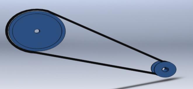
Adrivebeltcouldbeaversatileloopofrubber,or alternative similar material, that's accustomed connect 2 or a lot of pulleys. These belts ar
diagramFig1
1.1 Objective i. Todesignandanalyzethepowergenerationunitfor electricitygeneration. ii. Themainfocusofthisarrangementistheharvesting ofalargeamountofpowerusingsimplegeardrive mechanisms.
ii. Beltdrive
Rack&pinionusedamovementmotortohavean effect on the linear motion via a rack & pinion combination.they'reusedoftentimesinlongtravel applicationsthatneedhighstiffness&accuracy.
International Research Journal of Engineering and Technology (IRJET) e ISSN: 2395 0056 Volume: 09 Issue: 01 | Jan 2022 www.irjet.net p ISSN: 2395 0072 © 2022, IRJET | Impact Factor value: 7.529 | ISO 9001:2008 Certified Journal | Page916 Design and Analysis of Power Generation Unit Yashpal Kondgule1 , Pratiksha Kulkarni2, Aayushi Kharat3, Anand Malani4 , Mrunal Jondhale5 Prof. Ketki Shirbavikar6 1 5UG student Vishwakarma Institute of Technology, Pune 6Assistant Professor, Mechanical Engineering Department, Vishwakarma Institute of Technology, Pune, Maharashtra, India *** Abstract During this project our main aim is to get current employing a simplifiedmethodology. Non conventionalenergy is taking part in a really essential role now a days in our nation. As day by day, the necessity for energy is additionally increasing. However thanks to restricted typical energy resources we want to admit some non conventional energy resources. The energy obtained from railway tracks is one supply of generating non conventional energy as a result of there's no would like of fuel as associate degree input to get the output within the type of wattage and this can be done by victimisation easy gear drive mechanism. This mechanism carries the flap, rack and pinion, gears, freewheel, flywheel, DC generator, battery.
iii. To produce electricity by using non conventional energysourcesandutilizeitforvariouspurposes.
1.2 Block

vi.
accustomedtransferpowerfromthecrankorcam shafttothegenerator,steeringmechanismpump, andnumerousalternativeaccessories.
This speed which is sufficient to rotate the rotor of a generatorisfedintothegeneratorwhereanelectromotive forceisproducedthatgenerateselectricity. Thiselectricalpowercanbestoredinabattery. In this way electricity is generated using this power generationunit.
iii. Returnspring
iv. Dc Angeneratorelectrical generator could be a device that converts energy to current, usually victimisation magnetisminduction.Thesupplyofenergyisalsoa reciprocal or rotary engine external combustion engine, water falling through a rotary engine or waterwheel, an interior combustion engine, a turbine,ahandcrank,ortheothersupplyofenergy.
ToBatterycharge electric battery from AC we want a stepdownelectricaldevice,rectifier,filteringcircuit, regulatortotakecareoftheconstantvoltagethen wewillofferthatvoltagetothebatterytochargeit. assumeifyouhavegotsolelyDCvoltageandcharge theleadacidbattery,wewilljazzbygivingthatDC voltagetoa DC DCtransformer anda fewfurther electronicequipmentbeforegivingtotheleadacid battery
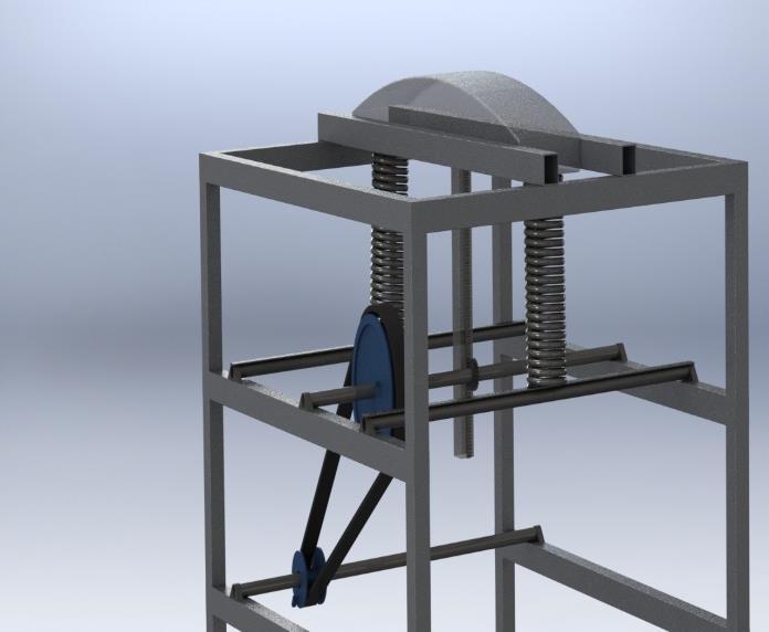
2. METHODOLOGY Whenatrainoranyvehiclemovesoverthetrackorroad, theloadactedupontheflapoverthetrackorplantsetupis transmittedtorack,pinionandbeltdrive arrangements. Wherethereciprocatingmotionofthepathofthevehicle is converted into rotary motion with the help of rack and pinionarrangement. Thenthisrotatorymotionisthenfedontothegeardrives whichsupplythismotiontotheothershaftwherethebelt driveislocated.
International Research Journal of Engineering and Technology (IRJET) e ISSN: 2395 0056 Volume: 09 Issue: 01 | Jan 2022 www.irjet.net p ISSN: 2395 0072 © 2022, IRJET | Impact Factor value: 7.529 | ISO 9001:2008 Certified Journal | Page917
Acomebackspringcouldbeaspringinaverykey switchthatkeepstheswitchopentillit'sironedand returns the slider to its home position when the switch is free. generally this can be a whorled (standardspiral)spring.
v. InShaftthe present model 2shaftsisemployed. One is employed to mount the gears. each the shaft has beenmountedonbearingstosupplyforresistance free rotation concerning its own axis. the masses working on the shaftar that of the weights of the parts mounted on the shaft, transmission masses andself weightoftheshaft.
3. CALCULATIONS i. Designofframe: ConsidermaximumloadontheframetobeW=50kg Force= W*g=490.5N ������=250MPa F.O.S.= Maximum5bendingmoment=Force*(perpendicular distanceofsquarebarlength) =269775N mm ����������w= Syt/F.O.S. = 50MPa ����≤����������w Thusweconsider,����=50MPa ����= forso.b=d=(M*y)/b34.87mmdesignpurposewehaveconsidered, b=d=35mm ����=Bendingstress M=bendingmoment I=Momentofinertia y= Distance of the layer at which the bending stress is consider ������=yieldstress ����������w=allowablestressformaterial ii. Designofspring: Diameterofwire(d)=10mm Meandiameterofwire(D)=85mm
International Research Journal of Engineering and Technology (IRJET) e ISSN: 2395 0056 Volume: 09 Issue: 01 | Jan 2022 www.irjet.net p ISSN: 2395 0072 © 2022, IRJET | Impact Factor value: 7.529 | ISO 9001:2008 Certified Journal | Page918 C= Dd= 8.5 KS =1+ 2C1 =1.05882 Assumingcarbonsteel materialofspring Modulusofrigidity(G)=77GPa Modulusofelasticity(E)=210GPa maximumallowableshearstressis��=350Mpa �� = (8*Ks*Fmax*D) (π*d3) Fmax= 1527.16 N Ks=Shearstressfactor Fmax=maximumloadthatspringcanhandlebeforefailure Deflectioninthespringisgivenby, δ= 8*F*n*D3 Gd4 n=no.ofactivecoils=23 δ=35mm. LengthofSpring Ls =nd Lf =Ls+1.15δ =270mm FreelengthofSpring=270mm Lf=freelengthofspring Ls=solidlengthofspring δ=deflectionofspring iii. DesignofRackandpinion: RackmR= Addendum1.5ofRack(AR)=1mR=1.5mm pressurempPinion:=1.5angle(ɸ)=20° To avoid interference on pinion minimum no. of teeth requiredaregivenby, t=[2*AR]/[sinɸ]2 tp =26 v1=Initialvelocityofrack v2=Finalvelocityofrack F=Forceontherack mR=moduleofrack tP =No.ofteethonpinion DP =mP *tP DP = 39 mm (pitchdiameter) Facewidth: σ= Pd = No.ofteeth/pitchdiameter Y=0.154 0.912T f= 9.36 mm Torqueactingonthepinion T=F(DP/2) T=2.58N m Power=time*deflectionforce P=T*⍵ N=65.14rpm f=facewidth Y=lewi’sformfactor Pd =Diametralpitch mP=Moduleofpinion DP=Diameterofpinion iv. DesignofShaft Forcalculatingdiameter ofshaft: maximumallowableshearstressis��=350MPa
International Research Journal of Engineering and Technology (IRJET) e ISSN: 2395 0056 Volume: 09 Issue: 01 | Jan 2022 www.irjet.net p ISSN: 2395 0072 © 2022, IRJET | Impact Factor value: 7.529 | ISO 9001:2008 Certified Journal | Page919 Torsionalshearstress,��=16*T π*d3 d=3.95mm Taking,factorofsafety=5 d=3.95*5=19.75mm Fordesignpurpose,Diameterofshaftd=20mmT=Torque d=Diameterofshaft v. Generator: N1=65.14rpm V.R=2.667 N2=N1*V.R N2=173.72rpm Based on availability in market we selected 400 rpm Ageneratorpairofgearisusedtoraiserpmfrom173.72to400 Minimumno.ofteethongeartoavoidinterferenceis18(T3 = N18) 4 N3 = T3 T4 T3 =41.42 T3=42 N3 =173.72rpm N4 =400rpm T4 =18 3.1 Material selection Srno. Component Material 1 frame mildsteel 2 spring carbonsteel 3 rackandpinion castiron 4 gear stainlesssteel 5 shaft mildsteel Table 1: materialselection 4. MODELLING OF PARTS IN SOLIDWORKS 1. Rectangularpipe Fig 2: rectangularpipe specificationsofrectangularpipe for base and railway track arrangement of cross sectional area2.35×35mm2.Shaft Fig 3: shaft Weareusingtwoshafts.Oneisusedtomountthegears.The otheroneisusedtotransmitthepower. 3. Pinion Fig 4:pinion specificationsofpinion Pressureangle 20 Facewidth 5.64 Module 1.5
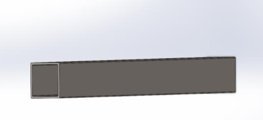
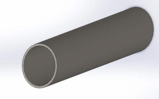
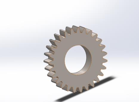
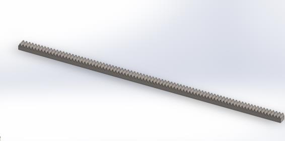
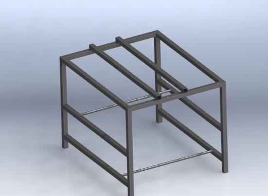
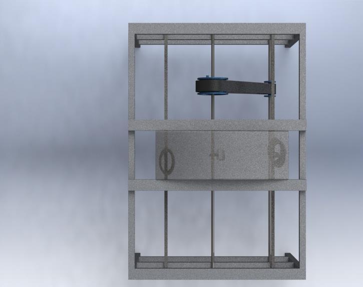
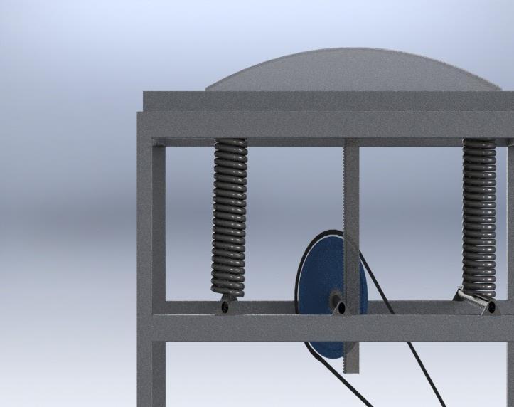
International Research Journal of Engineering and Technology (IRJET) e ISSN: 2395 0056 Volume: 09 Issue: 01 | Jan 2022 www.irjet.net p ISSN: 2395 0072 © 2022, IRJET | Impact Factor value: 7.529 | ISO 9001:2008 Certified Journal | Page920 Numberofteeth 26 Tooththickness 2.38 Wholedepth 3.268 Nominalshaftdiameter 20 4. Rack Fig 5 rack specificationsofrack Pressureangle 20 Module 1.5 Facewidth 10 Pitchheight 7.5 Length 400 5. Beltdrive Fig 6 beltdrive specificationsofbeltdrive 1)Bigpulley Outerdiameter 200mm InnerDiameter 20mm Thickness 60mm 2)Smallpulley Outerdiameter 40 InnerDiameter 20mm Thickness 60mm 3)Beltthickness 40mm 4)Beltlength 1140.96 6. Base Fig 7:basearrangement specificationsLengthofthebase 1100mm Widthofthebase 900mm Heightofthebase 800mm 5. CAD MODEL IN SOLID WORKS WehaddesignedthisprojectmodelinSOLIDWORKS. Fig 8
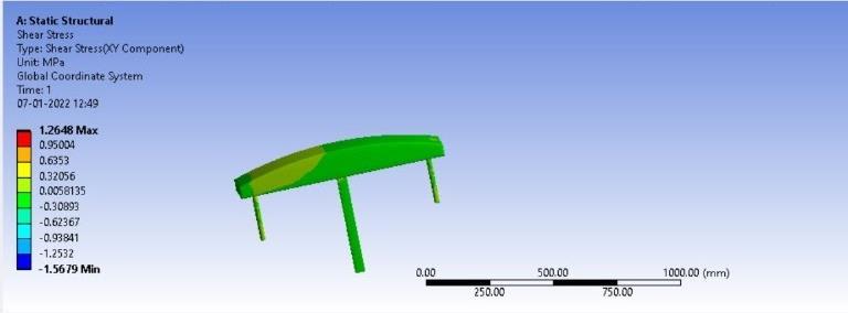
International Research Journal of Engineering and Technology (IRJET) e ISSN: 2395 0056 Volume: 09 Issue: 01 | Jan 2022 www.irjet.net p ISSN: 2395 0072 © 2022, IRJET | Impact Factor value: 7.529 | ISO 9001:2008 Certified Journal | Page921 Fig 9 Fig 10 5.1 Weight analysis : Component Weight(grams) Quantity (grams)weightTotal 1100mmRectangularpipes 2558.6 8 20468.8 800mmRectangularPipes 1860.77 4 7443.08 Rectangular 900 mmPipes 2093.37 4 8373.48 Circular 900mm Shaft 422.14 4 1688.56 CurvedSurface 99751.19 1 99751.19 Spring 3773.64 1 3773.64 Rack 80.76 1 80.76 Pinion 26.47 1 26.47 BigPulley 3406.23 1 3406.23 SmallPulley 149.02 1 149.02 Belt 544.57 1 544.57 TotalAssembly 150428.05 Table 2: weightanalysisofmodel 6. ANALYSIS ThestaticstructuralanalysisofthemodelisdoneinANSYS software. Fig 11: shearstressanalysis
1.Thisarrangementisslightlychangedtoconstructinfoot stepandthisarrangementismountedin •Schools, •Cinematheatres, •Searchingadvanced •Severalalternativejammedareas
2. Future aim of the analysis is to develop our country by enrichingitinutilizingitssourcesduringaalotofhelpful mannerforrailroadfurtherasdomesticapplications.there's associatedegreeeverincreasingdemandforenergyinspite of inflation of oil and alternative fossil fuels. this idea can facilitatetoboostalotofpowergeneration. Thismaybecreatedalotofcompactthusonbeutilizedin SpeedBreakers.
3.
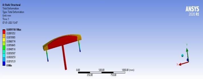
4. The deformation was discovered to be a most of zero.0091161mm.
Wewouldliketoexpressourdeepestsenseofgratitude towards our supervisor Mrs. Ketki Shirbakivar , Asst. Professor Department of Mechanical Engineering, Vishwakarma Institute ofTechnology,Pune,as well asMr. Mangesh Chaudhary H.O.D. of mechanical engineering, Vishwakarma institute of technology, Pune. for their inspirationalguidance,constantencouragement,andmoral supportinourprojectwork.
2. This sort of power generation is known to be cheaper than several alternative alternatives and thereforethemodelhaslessvarietyofelementsand therefore the assembly would value terribly less with all the elements being offered often and no model specific elements square measure to be factory made.
8. CONCLUSIONS
ACKNOWLEDGEMENT
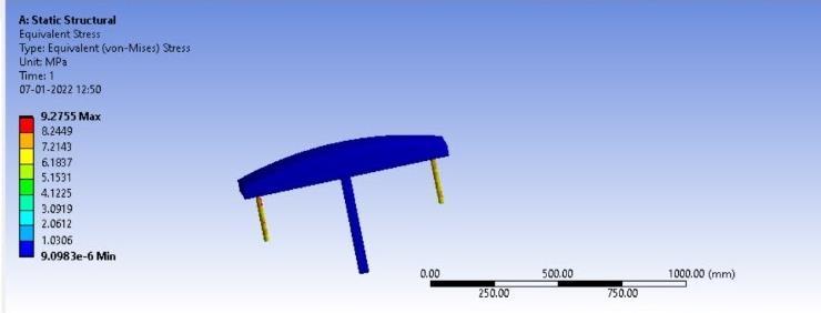
3. Within the analysis is it discovered that most equivalentstressisnine.2755MPa
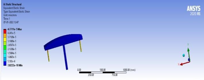
International Research Journal of Engineering and Technology (IRJET) e ISSN: 2395 0056 Volume: 09 Issue: 01 | Jan 2022 www.irjet.net p ISSN: 2395 0072 © 2022, IRJET | Impact Factor value: 7.529 | ISO 9001:2008 Certified Journal | Page922 Fig -12: equivalentstressanalysis Fig 13: totaldeformation Fig 14:equivalentelasticstrain 7. APPLICATIONS Powergenerationunitmaybeutilizedinallrailwaytracks furtheras1.Attheentryandexitoftheautomotiveparking oftheshopsasimilarsystemmaybeaccustomedgenerate theelectricity.2.Allhighwaysroadspeedbreakers. 7.1 Future scope
1. Duringthisprojectelectricpowerwasgeneratedby employingarackandpinionmechanism.
International Research Journal of Engineering and Technology (IRJET) e ISSN: 2395 0056 Volume: 09 Issue: 01 | Jan 2022 www.irjet.net p ISSN: 2395 0072 © 2022, IRJET | Impact Factor value: 7.529 | ISO 9001:2008 Certified Journal | Page923 REFERENCES [1] VISHWANATH HIREMATH,“Design and Fabrication of Power Generation unit From Railway Track”,InternationalJournalofScientific&Engineering ResearchVolume11,Issue6,June 2020ISSN2229 5518 [2] JagdishChahande,“ElectricityGenerationusingRailway Tracks”,GRDJournalforEngineering|Volume2. [3] V.BBhandari,“Designofmachineelements”,tatamcgraw hill,3rdedition(2010) [4] H.Abramarich,E.Harash,Milogram,Amit,Azilay,“Power Harvesting from railways; apparatus, system and method”,USpatent7812508,2008. [5] https://www.ijert.org/techniques for generation of electricity from moving vehicle