International Research Journal of Engineering and Technology (IRJET) e-ISSN:2395-0056

Volume: 09 Issue: 11 | Nov 2022 www.irjet.net p-ISSN:2395-0072
Abstract - The purpose of this project is to investigate potential effects on manufacturing using the same conventional methods of production, where many issues, including low production, high labor costs, poor quality, and safety, are caused by its current working practices in an observed industry (Tuljai Engineering Works), which is located in Pune, Maharashtra. First, the study focuses on the line balancing methodology in order to address this current method. Line balancing is a useful technique for enhancing shop layout, which shortens the time it takes to produce a product. Additionally, there are several benefits to cellular manufacturing, including greater quality, increased productivity, and improved machine usage. The company is now dealing with issues including worker injuries, low productivity, excessive labor costs, poor quality, etc. The entire process must be automated in order to handle this issue.
The effectiveness of automated high speed part feeding is crucial to the outcome of automated assembly in batch or mass production. For this task, a standard vibratory bowl feeder is practical under these circumstances. The goal of this project is to advance the implementation of a flexible vibratory bowl feeder. The rigidity of tool orientation is to blame for the issues incorporated. This study devised a strategy for uptime maximization and evaluated the total production downtime for each production line each shift. To emphasize some concerns with material circulation to the plant floor, the corporation also acquired a manufacturing layout. The business also utilized to compare cycle time, Takt time, and overall equipment effectiveness with downtime (OEE).
Key Words: Cellular Manufacturing, Productivity, VibratorybowlFeeder,OverallEquipmentEffectiveness
1Introduction
Manufacturing is a crucial business activity performed by businesses that offer goods to consumers. Manufacturing today entails a variety of interconnected tasks, such as product design and documentation, material selection, process planning, production, quality assurance, management,andproductmarketing.Toproduceproducts
that are both feasible and competitive, these activities should be combined. In the conventional manufacturing process, the work item is manually fed onto the turning machine.Toloadtheworkitemontothemachinecollet,the operator holds it in his hand. There are safety risks as the workpieceisputontothemachineandheldinplacebythe collet for the simultaneous chamfering and grooving operations. Coolant circulates constantly while the turning operation is being completed to facilitate efficient machining. Following the completion of the turning operationontheworkpiece,thejobisautomaticallyejected or unloaded by the machine, and additional work is placed inastoragebin.Aftertheworkpiecehasbeenunloaded,the operator feeds a new work piece into the machine's collet for turning. An action that happens sequentially. To clean and remove burr, the stored work components are submerged in LH3 grade oil for 10 minutes. Before being sent to the packaging department, the work items undergo randominspections.Thus,thecompany'soldmanufacturing method causes issues like operator injuries, low productivity, excessive labor costs, poor quality, etc. The entireprocessmustbeautomatedinordertodealwiththis circumstance. Manufacturing technology has undergone constant, incremental yet revolutionary change. The manufacturingindustryhas undergone a metamorphosisas a result of these technological breakthroughs. The single biggest cause of lost production time for the majority of manufacturers is downtime. Given how noticeable equipment breakdowns and failures are, it attracts a lot of attention.
1.1 Objectives
To make loading and unloading of the work piece automaticallyi.e.,processautomation.
Utilization of appropriate shop-floor by using cellular manufacturingApproach.
To Compare the various automation for feeding system andchoosethevibratorybowlfeederistechnicalviable thanotherfeedingsystem.
To compare the Productivity of machine shop before andafterimplementationofvibratorybowlfeeder.
“Development of automatic feeder system in cellular manufacturing to improve productivity of Traub machine shop.”Abhinandan Shinde1 , Dr.R.K Shrivastava2 1Student, Mechanical Engineering, Government College of Engineering, Karad, Maharashtra India. 2Professor and Head Department of Mechanical Engineering, Government College of Engineering, Karad, Maharashtra ***
International Research Journal of Engineering and Technology (IRJET) e-ISSN:2395-0056
Volume: 09 Issue: 11 | Nov 2022 www.irjet.net p-ISSN:2395-0072
To reduce the downtime of machine using Overall equipmenteffectivenesstechnique.
1.2 Problem definition and identification
Amanagementatseveral ofthebusinessesI'vevisitedcan detail every cent that goes toward an operator's cost (again, wages plus benefits). One business I went to even mentionsthepriceoftheparkingplacetheemployeeuses to keep their vehicle. However, they are not nearly as aware and careful when it comes to machine prices. Once more, the key to making informed judgments about operator usage is having an accurate estimate of both the cost of the operator and the machine. Poor operatorutilization decisions are caused by inflated operator costs and depreciated machine costs. It will seem more costeffectivethanpastmethodstouseoneoperatorfortwoor more machines Initially there were 24 machines, which were operated by 24 skilled operators along with 4 unskilledoperatorsorhelpers.
Probleminpresentare,
1. Manualoperationhencelessaccuracy.
2. Skilledworkerrequired.
3. Productiontimedependsuponoperatorskill.
4. Toolbreakdownproblemduetomisalignmentof part.
5. Machiningsafety
6. Linebalancingoftheshop-floor.
1.3 Downtime
A system or machine is considered to be in downtime when it is not functioning properly. It describes the moment when a company's plant is not turning out goods in the manufacturing sector. Since unplanned downtime frequently happens while regular business operations such as paying employees and ordering materials for product manufacturing continue, this can negatively affectacompany'sbottomlineandprofitmargins. AvailableLosses PerformanceLosses Quality
Losses
1.4 Traub machine shop
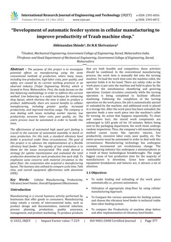
ATRAUBmachineisatoolthatprovidesgreatprecisionat a reasonable price and is frequently appropriate for mass producingprecisionparts.Electrical,textile,electronic,and generalengineeringsectorsfrequentlyusethesemachines. TRAUB machines are available in a variety of models, includingtheC15,C-25,C-30,C-32,C-42,andC-60,tomeet
all of your industry's needs. These devices offer great returnsonasmallinvestmentandareincrediblyadaptable.
Fig1Traubmachine
2. Cellular manufacturing
Cellularmanufacturing isa methodof producing goods that sets up workstations and equipment in a specific order to allow things to pass through the production process as quickly as possible while requiring the least amount of waste and logistical work. Cellular manufacturing, a subset of just-in-time and lean manufacturing, tries to set up machinery, tools, parts bins, and workstations to allow for an optimum flow of continuous production from one cell to thenext.Cellsareoftenmadetoprocesspartsoneatatime as opposed to simultaneously processing a batch of components in a workstation. This makes it possible to produce more similar goods more quickly since individual cells can be modified without rearranging the entire assemblylinewheneveravariationisrequired.Eachcellhas adistinctindependentproducingunit.Dependingonthecell sequence,eachcellmayhaveadesignatedspecialistormay have workers who have undergone cross-training to supervise the operation of other cells or the entire cell sequence. Whilea cell maygeneratefinishedproductsfrom beginningtoend,mostoften,cellsaresetupinaflowwhere the output of one cell serves as the input for the following
2.1 Types of cell layouts
2.2Implementation process
There are various processes involved in the creation of a work cell. The first step is to classify the company's items intofamilies.Theseproductclusterscouldbecomponentsof one and the same design that simply differ in terms of size, shape, or functionality. They could also be Categorized Accordingtotheproductionprocess,suchasbyprocessstep or order of operations. Second, families should be grouped using a production flow analysis (PFA). In this case, it is
2022, IRJET | Impact Factor value: 7.529 | ISO 9001:2008 Certified Journal | Page378
International Research Journal of Engineering and Technology (IRJET) e-ISSN:2395-0056
Volume: 09 Issue: 11 | Nov 2022 www.irjet.net p-ISSN:2395-0072
crucial tochoosemachinestoclusterthatcomplementthe components of each family. It aids in estimating the quantity of raw materials and spare parts that will be needed. In many cases, combining family parts might help you reduce your parts inventory. With only a minor alteration, a single part might be found to be compatible with another finished product. By the cell’s equipment. Finally, the cell's internal activities can be optimized .This may contain noticeable components like the number of steps between stations within a cell or the routing's distance from one cell to the next. Planning for material handling, station-to-station product flow, fixed manufacturingexpenses,andlaborcostsmayalsobeapart ofit.
2.3 Line balancing in manufacturing
Line balancing is a production strategy that involves balancing operator and machine time to match the productionratetothetakttime.
By combining people and machines into one work station for mass production, line balancing is done on the factory floor to save idle time. Because of the high rate of production in this layout and the need for effective machineandoperatorbalanceforincreasedefficiency,line balancing is employed in product designing. Takt time is thepaceatwhichcomponentsorgoodsmustbeproduced to keep up with demand from customers. Production time mustmatchtakttime preciselyfor a given production line to be properly balanced. If not, resources should be redistributed or reconfigured in order to eliminate bottlenecks or excess capacity. To put it another way, a new balance should be struck between the numbers of workersandmachinesallocatedtoeachdutyontheline.
2.3.1 Benefits of Line Balancing
3 machine shop layout of traditional manufacturing and cellular Manufacturing
3.1 Traditional shop floor layout
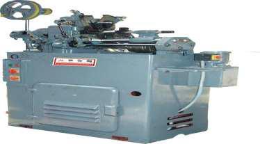
24 machines were handled by 24 personnel in the traditional shop floor configuration (figure2), which resulted in the several drawbacks mentioned above. Additionally, the long product cycle time needed under the currentcircumstancesledtolowproductivityandinefficient machine use. To overcome, we have created new or modifiedshopfloorlayoutsusinglinebalancingtechnique
Fig2Traditionalshopfloorlayout
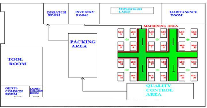
3.2 Implementing shop floor layout
Aswasmentionedintheproblemdefinition,thisindustryis having issues with shop floor line balancing and space usage. We have accomplished line balancing approach with theuseofaredesignedshopfloorlayout(asshowninfigure 3.7).Fourmachinescan be operatedinthismodifiedlayout by a single worker, resulting in a reduction in labor costs. Product cycle time has been shortened by applying a changed shop floor layout, leading to high productivity, a reductioninspace,andimprovedequipmentusage
Fig3Implementingshopfloorlayout
International Research Journal of Engineering and Technology (IRJET) e-ISSN:2395-0056
Volume: 09 Issue: 11 | Nov 2022 www.irjet.net p-ISSN:2395-0072
4 Automatic feeder system in traub machine
Today, every manufacturing sectormustworktodevelop efficient production processes while also reducing
production costs. This pushes every business to adopt smart manufacturing, wherein the company leverages the technologyofthetoolstheyalreadyhavetocreatethebest possiblemanufacturingenvironment,butstillreliesonthe role of humans who still have control over these equipment. This is due to the fact that the manufacturing industry relies heavily on its machine technology and the caliberofitshumanresources,whichcanbereferredtoas the role of humans. In this post, we'll talk about an equipmentortechnologycalledafeedermachinethatisn't oftendiscussedintheindustrialindustry.aThistime,we'll talk about a machine that is really helpful in the manufacturing industry: the feeder machine. A feeder machineis,by definition,a device thatis used to"load" or "feed" a product or object in order to increase production and make it more efficient. In other terms, a feeder machineisdescribedasadevicethatfeedsitems,packing, or containers one at a time before directing them along a conveyor. Depending on the intended function, this machinecanbeintegratedwithothermachines.Inorderto control the flow of bulk materials into the machinery for additional processing or another operation, a feeder is a pieceofmaterial handlingequipment.Essentially,afeeder is a conveyor used when a uniform rate of dispersion is required over short distances. Depending on how they operate, there are many different types of feeders to suit manydifferentindustries.
4.1 Parts Feeders Function
The crucial tasks of locating pieces and controlling flow rate are performed by all parts feeders, regardless of whether they rely on centrifugal force, mechanical vibrations, or gravity. Centrifugal feeders are recommended for packaging tasks or handling fragile parts,whilevibratoryfeedersaretypicallybettersuitedfor productionprocess.Thefollowingarethetoptwoservices thatfeedersystemsoffer:
4.3 Technical Comparison of Automatic feeder system
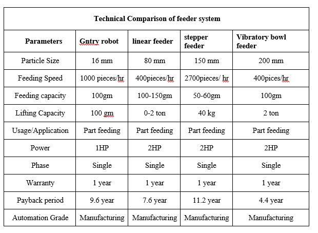
Fig4TechnicalComparisonofAutomatic Feedersystem
4.4 Comparison of proposed automation
Manufacturing industries must replace their outdated infrastructurewithonethatismoreadaptableanddynamic. Theseshiftshavegivenrisetoseveralnewideas,supported by tactics designed to handle problems brought on by international marketplaces. We sought to use process automation, such as a robotic arm and vibratory bowl feeder, to get around the conventional manufacturing method. When compared to the other two technologies, the robotic arm has several limitations and is very complex. Robotic arm assembly requires a lot of mechanisms, electricalparts,sensors,andmicroprocessorcontrolunits.It requiresmorelaborandpossiblyusesmorespace.Asthere are24machinesinthisindustry,24automaticfeedersmust be installed for process automation, and high precision, accurate programming is also required with a skilled programmer to develop an appropriate program. Thus in case of small scale industry automation by robotic arm linearfeederstepperfeederisnotaffordable
Parts must be accurately reoriented for feeding into an assembly line in manufacturing, where component feeding for automatic assembly is a critical issue. In this sector, vibratory bowl feeders are used to feed and realign pieces into a specific arrangement. Vibratory bowl feeders have various benefits, including being energy-efficient, relatively inexpensive, of sturdy construction, portable, etc. Manufacturers can save time and money by using vibratory feedersinsteadofmanuallabor.Whenasetnumberofwork components are waiting in line on an inclined rail, it also reduces power usage. When comparing automation by robotic arm versus automation by vibratory bowl feeder, it isclearthatthelatterismorepracticalandcost-effective.In light of this, this report recommended automation using a vibratingbowlfeeder
International Research Journal of Engineering and Technology (IRJET) e-ISSN:2395-0056
Volume: 09 Issue: 11 | Nov 2022 www.irjet.net p-ISSN:2395-0072
5 Working setup of automated mechanism
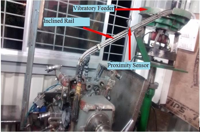
A vibrating bowl feeder is the most frequent tool used to feed industrial parts. The internal wall of the basin is climbed via a helical track. If the bowl is vibrated in a circularmotion,partsdumpedintoitwillclimbthehelical track in a single file. As they ascend the track, the pieces encounter a succession of obstacles that either reorient them or lead them back into the middle of the bowl. Stepper motor operated wiper blades and programmable track width are utilized in place of welded passive orienting devices, such as wiper blades, and permanently constructed orienting devices on the track to make the bowlfeederadaptableandprogrammabletoaccommodate pieces of different sizes. An electromagnet placed on the base of a bowl causes vibrations, and The support system limits the range of motion. The vibratory motion that occurs when parts are introduced into the bowl causes them to climb the track to the exit at the top of the bowl. Figure 6 of the schematic for the vibrating bowl feeder is shownbelow.
The work piece moves progressively along a predetermined helical route as soon as the feeder is powered up and starts vibrating with a certain amplitude. As soon as a job arrives at the wiper blade station, it is rejected or wiped off if it is stacked on top of another one orexceedsthewiperblade'spredeterminedheightlimit.a commonpassiveorientingdeviceusedinthevibratoryThe wiper blade station is in the vibratory bowl feeder and is used to reject or wipe off operations. After passing the temporarywiperbladestation,thework itemmovesonto the deflector station. Here, a deflector station at a 90degreeangledeflectsthejobsbeforetheycontinuealonga slantedtrackinthedirectionofthemachinecollet.Similar tothis,whentherearelotsofavailablepositionsAprecise spot inside an inclining rail houses the proximity switch sensor. The sensor on the inclined rail will complete the closeloop.Asensorwillturnoffthepowertothevibrating hopperwhentheworkloadexceedsthesensor'sthreshold. By disabling the vibrating hopper's power source when it isn'tinuse,wemaycutpowerconsumptioninthisway.
6 Overall Equipment Effectiveness (OEE)
Overall equipment effectiveness is a gauge of how successfully a manufacturer runs its business (OEE). In other words, total equipment efficacy helps us identify operational issues, determine how much of the production timeisactuallyproductive,andsolvethem.Italsogivesyou areliableyardstickformeasuringprogress.ThegoalofOEE measurementiscontinuousimprovement.
6.1 Overall Equipment Effectiveness (OEE) to Measure Manufacturing Productivity
An impressive number is the equipment efficacy overall. OEE is used to quantify manufacturing productivity in a varietyof ways sinceitgivesa lotofinformationina single value. It can greatly increase your production if estimated and understood correctly. When comparing a specific production to industry standards, internal equipment, or other shifts using the same piece of equipment, overall equipment effectiveness is utilized as a comparison. These arethetypicalOEEbenchmarks:
Perfect production is defined as having an OEE score of 100 percent, which indicates that the business produces only high-quality items as soon aspossiblewithnodowntime.
Fordiscretemanufacturers,anOEEscoreof85%is regarded as world class and is a long-term objective.
Discrete manufacturers often have an OEE score of 70%,whichindicatesthereismuchopportunityfor improvement.
While considered low, an OEE score of 40% is not unheard of for manufacturers just starting to monitor and enhance performance. In most circumstances,alowscorecanbequicklyraisedby takingsimpleactions
6.2 Overall Equipment Effectiveness: Terms
Before we discuss overall equipment effectiveness further, therearesomeimportanttermstobeawareof.
Quantitative Efficiency - This refers to manufactured parts that don't meet quality-control standards,includingonesthatneedtobereworked. Itiscalculatedas
QuantitativeEfficiency=
Performance Efficiency - This takes into account the number of times there are slowdowns or brief stopsinproduction.Aperfectperformancescorein OEE terms means your operation is running as quicklyaspossible.Itiscalculatedas
International Research Journal of Engineering and Technology (IRJET) e-ISSN:2395-0056
Volume: 09 Issue: 11 | Nov 2022 www.irjet.net p-ISSN:2395-0072
Performance=
Availability Efficiency - This takes into account planned and unplanned stoppage time. A perfect availability score means your operation is constantly running during planned production times.Itiscalculatedas
7 Important Definitions
1TAKT time:
TAKTtimeisderivedfromGermanwordTAKTZEITwhich means meter. TAKT time is the rate at which the product must be produced in order to meet client demands. TAKT time synchronizes the manufacturing process' speed with customer demand Each manufacturing process works to TAKT. It is the ratio of total time available for manufacturing of any product to the total demand of that product to the customer. All the activities that are necessary for the completion of any product must be completed within the TAKT time of line otherwise it will leadtofabricationofbottleneckattheline.Itisalsocalled thecycletimeofline.
TAKTTime =
2 Cycle time:
Cycle time is the amount of time for operator spends actually working on producing on aproduct. It is the averagetime
Cycletime=
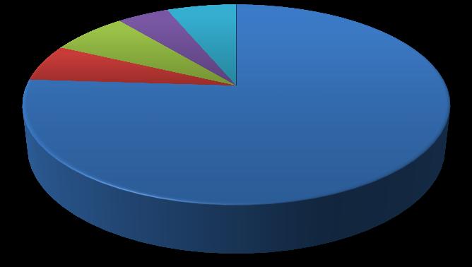
8
distribution of old process
Cost details of 24 machines for one month are shown in table 1 Here The most contributing parameter is labor costing which is 75% of total production expenditure. So, projectmainlyfocustooptimizelaborcost
9.4 CALCULATIONS
1 TAKT Time
TAKTTime= =9sec 2 Cycle Time CycleTime= =8.8sec
IdealOEE = × × = × ×
IdealOEE=91.66%
NetProductiontimeavailable=440min.Targetforthe production=3000units.
Thetotaltimeavailable=450minpershift.
ActualProduction (before implementation)permachine = 2290units
ActualProduction (afterimplementation) per machine = 2760units.
Performance Efficiency (before implementation)= = 71.56%
Performance Efficiency (after implementation) = = 86.25%
Quantitative Efficiency (before implementation) = = 76.33%
Quantitative Efficiency (after implementation) = =92%
International Research Journal of Engineering and Technology (IRJET)
e-ISSN:2395-0056
TM8 0.522367 0.683022
TM9 0.336742 0.704531
TM10 0.460763 0.690038
TM11 0.430468 0.673213
TM12 0.436184 0.675736
TM13 0.465981 0.683658
TM14 0.435467 0.707128
TM15 0.419178 0.684294
TM16 0.402142 0.720861
TM17 0.462499 0.720861
TM18 0.298179 0.677315
TM19 0.465483 0.714301
TM20 0.493923 0.696455
TM21 0.510129 0.698066
TM22 0.423155 0.680482
TM23 0.515959 0.694847
TM24 0.440984 0.709405
Average 0.434603 0.701567 0.4346 0.7015 43.46% 70.15%
10 CONCLUSION
1. The rise in Production clearly seenas for 1st Shift is17%andfor2nd Shift is18%
2. Therejectionofjobsisreducedby72%
3. Thereductionindowntimeis60%.
4. Availabilityofmachineisincreasedby8%.
5. Average overall equipment effectiveness increased 43.46%To70.15%.
6. Theproductionexpenditureisreducedby22.90%
11 REFERANCES
1. Negahban, A., & Smith, J. S. (2020). Simulation for manufacturing system design and operation: Literature review and analysis. Journal of ManufacturingSystems,33(2),241-261.
2. Askin, R. G. (2019). Contributions to the design and analysis of cellular manufacturing systems. International Journal of Production Research, 51(2324),6778-6787.
Volume: 09 Issue: 11 | Nov 2022 www.irjet.net p-ISSN:2395-0072 © 2022, IRJET | Impact Factor value: 7.529 | ISO 9001:2008 Certified Journal | Page384
3. Nouri,H. A.,Leman, Z.,Moghadam,H. P.,& Sulaiman, R. (2014). Literature review on machine reliability in cellular manufacturing system. Am J Appl Sci, 11(12), 1964-1968.