International Research Journal of Engineering and Technology (IRJET) e-ISSN:2395-0056

Volume: 09 Issue: 11 | Nov 2022 www.irjet.net p-ISSN:2395-0072
International Research Journal of Engineering and Technology (IRJET) e-ISSN:2395-0056
Volume: 09 Issue: 11 | Nov 2022 www.irjet.net p-ISSN:2395-0072
1P.G. Student, 2Associate Professor & Chairman, 3Assistant Professor, 4Director-Aerospace R & D, 1-3Department of Aerospace Propulsion Technology, Visvesvaraya Technological University-Centre for Post Graduate Studies, Bengaluru Region,VIAT, Muddenahalli, Chikkaballapura, Karnataka, India.
4Dautya Aerospace Pvt Ltd, Bengaluru, Karnataka, India. ***
Abstract - The scope for electric vehicles growing rapidly now a day. There are many reasons behind the requirement for the development of electric vehicles such as fuel cost, air pollution due to emissions, fuel availability. In similar manner considering the current aviation industry, the aviation has developed a lot. However, there are many challenges the industry needs to be faced such as fuel consumption,costofthe fuel and air pollution due to emissions caused by gas turbine engines on environment. Since fuel cost, fuel availability and consumption are the major problems in current aviation industries, electric aviation may help in this. But as we know, in the current technology only a propeller driven by amotorto produce thrust will be used as an electrical engine, andthereis no air breathing electrical engine exists. For a better propulsion technology, we propose here a concept of‘Magneto Propulsive Solar Aircraft Engine’ to achieve pollution less aviation environment. In this work, an exterior rotor motor is designed and viewed in the point of an embedded engine for the hub of a designed ducted propeller. This configuration is designed along with a normal shaft driven ducted propeller and performance of both the configurations are analyzed and compared for power consumption, torque demanded and inertial aspects and the new concept of embedded motor propulsion technique is introduced for lightweightelectricand solar aircrafts as ‘Magneto Propulsive Solar Aircraft Engine’.
Key Words: Electrificationtechniques,Brushlessmotor, Torqueextraction,3DPrinting,Computationalsimulation, Rotor and Stator configuration, Input DC current, Output power,Coggingtorque,Phasecurrent,Magneticfluxdensity, Solarpropulsion, Mass flow rate, Propellerdrive configurations,Freestreamconditionsetc.
Commercial aviation has become a great importance of today’saviationindustry.Alongwiththe evolvingaviation industries, the air traffic has become a major part since jetliners. The current aviation industries are facing the dominantchallengesthatincludeaerodynamicnoise,climate change due to emissions and decreased local air quality because of higher air traffic. Since commercial airliners breath using fossil fuels, the impact of emissions by the aviationonenvironmentisquitegreater.Duetoincreased airtraffic,anthropogenicemissionsoftheaviationhaveled
toenvironmentalclimatechangeandsurfacewarming.Since emissions are mainly because of gas turbine engines, electrificationofcivilaviationisquitehelpfultoreducethese impactsonenvironment.
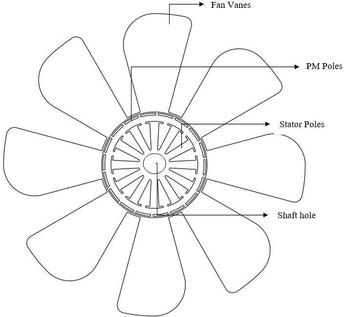
Overviewing current electrification techniques, the all –electric and hybrid electric or turboelectric types of electrificationsareintroduced.Intheseelectricpropulsion techniques,anaircraftispropelledbymeansofapropeller whichisdriventhroughamotorthroughbyacontroller.For thepowersupplybatteriesareusedinanall–electrictypes ofaircraftwhereasinaturboelectricaircraftthebatteryis rechargedthroughsmallgasturbineengines.
Thepurposeofthisworkistointroduceamotorembedded propeller system, instead of using a motor and a shaft –mountedpropellertodriveanelectricaircraft.Themotorin an electric aircraft plays a major role through its performance, weight, speed, torque and especially rotor inertia.Sincetherotorinertiaiscapabilitytoresistthespeed changeOFthemotorbecauseofexternalloadvariation,this makestherotorinertiaasasignificantproperty.Sincethere aremanyconfigurationsofrotorexistforaradialfluxmotor suchasouterrotorandinnerrotor,thecontributionofrotor inertiavariesforeachconfigurationtype.Sinceinertiaisa mass–dependentproperty,increasingmasscanreducethe performanceoftheaircraft.Hencedesigningamotorhaving highrotorinertiawithlessweightisachallengingtasktoget betterperformance.Asasolutiontothis,insteadofusingan interior rotor or shaft – mounted propeller system as a propulsion technique, an exterior rotor motor embedded propellerisintroducedasobjectiveofthiswork.
Nowadays,BrushlessandPMSMmotorsweretakingplacea large applicative opportunity in every automotive and aerospaceindustriesbecauseofitsadvantagessuchaslight weight, high efficiency, lower or needs no maintenance comparedtoothermotortypes.However,becauseofelectric aircraft needs a lightweight, higher efficiency motor, a brushlessorPMSMmotorisfoundtobeagoodchoice.Since theintensionofthisworkisalsotoconsidersolarpowered aircrafts,motorcharacteristicswaschosenorientedtothis.
2022, IRJET | Impact Factor value: 7.529 | ISO 9001:2008 Certified Journal | Page299
International Research Journal of Engineering and Technology (IRJET) e-ISSN:2395-0056
Volume: 09 Issue: 11 | Nov 2022 www.irjet.net p-ISSN:2395-0072
The brushless and PMSM type of DC or AC excited electromagnetic machines are of higher scope in current daysbecauseofitslightweight,highefficiencyandsmoother qualityperformanceduringoperation.Thiswillbeattracted by current electric aviation because of its efficient characteristics.Thedifferencebetweenanexterior–rotor andinterior–rotortypeofmotorconfigurationshasbeen noted. Then based on the study, an outrunner motor is designedinAnsysmaxwellenvironmentinorientationwith light weight and solar propelled aircrafts. The designed motorhasbeenanalyzedforitsperformancecharacteristics insteadyandtransientstates.
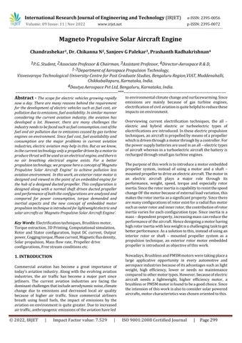
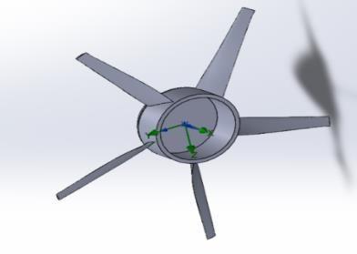
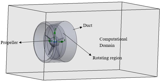
AHybridpropulsiveengineisageneraltechniqueproposed as modified approach to the current electric aircraft propulsion system. As the system consist of an embedded exterior rotor motor, a simple lightweight square wave excited3phasebrushlessdirectcurrentmotorisdesigned first using Ansys Rmxprt and steady state, transient performancewasanalyzedforexpectedtorqueandpower characteristics.Sincetheuseofsensorsinthemotorcanbe affected by the surrounding temperature, a sensor-less control was assumed during the process. Then, by using designed motor configuration, an axial fan was designed such that the whole system contributes to a motor embedded propeller as shown in Figure 1.2. Further, flow analysis is done on the shaft mounted fan and the motor embedded fan to analyze the advantages of integrating exterior rotor to axial fan vanes instead of using a shaft mountedfan.Theconclusionisapproachedbyconsidering theperformanceofthemotorneededtoachieveaspecific flightinboththecases.
There are many electrification techniques has been introduced such as all – electric, hybrid electric and turboelectric aircrafts. The general propulsion techniques behind these electrification techniques have been understood by referring to sufficient number of scientific publications. Then the idea of embedded motor propeller driving concept has been verified by referring to current motortechnologiesinaviationindustry.
Basedonthecharacteristicoutputbythedesigned motorsuchaspoweroutput,rotationalspeedandmaximum torque,Aductedpropellerhasbeendesignedbyconsidering power input as rated power output by the designed electromagnetic machine. The analytical design of ducted propellerismadewiththehelpofPython3.8environment by considering theoretical aspects from blade element moment theory. With the same blade configuration, the designedembeddedmotorductedpropellerisremodeledfor shaftdrivenone.Thenthepropellerducthasbeendesigned identicallyforbothconfigurations.
Sincethefreestreamflowconditionsduringflightwerenot always same, the propeller experiences the airflow with variationalloadconditionsactingonitthroughouttheflight. Hencewithaconsiderableamountoffreestreamturbulence, boththeductedpropellershavebeensolvedinSolidWork’s Flow simulation environment to get accurate torque demanded by both the configurations. And then the extractedtorqueiscomparedamongthebothconfigurations toachieveasuitableconclusion.
Whentheobjectiveofandesigninganaircraftistoreduce thekerbweightandhencetoincreasethepayloadcapability, the weight of every component has to be reduced by an amount. When considered a fan, the weight should be minimized and thrust capability of the fan should be increasedinpointofviewwithincreasingpayloadcapability ofthewholeaircraft.Byconsideringinertiaofthefan,the fanhavinglargerinertiacanberesistanttorotationalspeed variationwhensubjectedtovariableloadingconditionsdue to flow field. In other words, a fan having higher mass or largerhubcanbemoreresistanttospeedchangecompared tothefanwithlessmassorsmallerhub.
International Research Journal of Engineering and Technology (IRJET) e-ISSN:2395-0056
Volume: 09 Issue: 11 | Nov 2022 www.irjet.net p-ISSN:2395-0072
RFD:RelativeFluxDensity(T) 1.07
ForceofCoercion(A/m) 820000
EnergyDensityMaximum(J/m3) 219350
RecoilPermeabilityRelative 1.03842
DensityofDemagnetizedFlux(T) 653076 Remanence(T)(T) 1.05
Inshaftmountedfanorapropeller,thespeedvariationhasa contributionwiththerotorinertiaofthemotorandtheselfinertiaofthefan.Thisinturndemandsahigherinertiaofthe rotorforsmootherpropulsionwhileoperatingwithvariable externalloading.Asasolutiontothisonecanchooseamotor with higher rotor inertia and higher torque. While consideringaninteriorrotormotor,sincetherotormounted interiortothestatorwindings,theonlyoptionistoextend therotortoashaftformountingofapropellerorafan.But whileconsideringanexternalrotormotor,sincetheexterior bodyofthemotorrotates,onecanvarytherotorinertiaby addingorremovingmaterialontherotor.Thiswillcreatean opportunitytoobtainrequiredtorquebyhavingregulation on rotor inertia. Since the position of the rotor in an outrunner motor is made inside out, the diameter of the rotor is increased. Because of the inertia is a diameter dependentproperty,itwillbeincreasedforanexteriorrotor motorwhencomparedwithaninrunnermotorwithsame performancecharacteristics.
The choice of permanent magnet depends on its Working Temperaturerange,RadiationSensitivityandtheproperty whichshowsresistancetotheCorrosion.Sincereferenceto thetemperatureismoreimportantinthisapplication,the PMhavinghigherCurietemperaturehasbeenselected. The Samarium–Cobalt(SmCo)magnetsthecurietemperatureis around 8000C as observed, while for the Neodymium –Boron(NdFeB)magnetsitisaround3300C.Asaresult,the SmCo28 is selected as a magnet grade which has Curie temperature of 7500C-8200C and maximum working temperature of 3000C. The properties of selected magnet gradearelistedinbelowtable.
Whilechoosingamagneticcorematerial,thecorelosses shouldbetakenintoaccount.Sincethecorelosseshave adirectimpactonthemotor'seffectiveness,itshouldbe lessforchosencorematerial.Fora3-phasestator,ifthe No. of Magnetic Poles increase, then fundamental Electrical-Frequency also increases with respect to chosenno. of poles. And if the Frequency which to be supplied is ahigher value, the core losses of the stator and yoke material increases. Hence the material should be chosen by taking all these approaches into consideration. The material properties of the chosen core material 10JNEX900 are given in below table with thecorelossesat differentfrequencies.
Parameters Value Parameters Value
Coilpitch 1 Toothwidth 18 mm
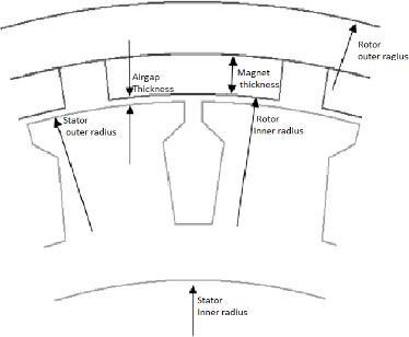
Statorouter radius 220 mm Rotorinner diameter 222 mm Statorinner ringdiameter 182 mm Rotor'souter diameter 248 mm lengthofthe backiron 7mm Poleembrace 08 Slotdepth 19 mm Slotfillfactor 07
Averageslot width 8mm Slotopening width 3mm Numberof poles 20 Numberof slots 24 Magnet thickness 6mm Airgaplength 1mm
Table-2: Propertiesof10JNEX900electricalsteel
Theprimary aspectis that thepolenumber depends on the applied fundamental square wave or sine wave frequency and required rated speed. Illustratively if the numberofPMpoles in a typical 16kW machine is two, then in order to
International Research Journal of Engineering and Technology (IRJET) e-ISSN:2395-0056
Volume: 09 Issue: 11 | Nov 2022 www.irjet.net p-ISSN:2395-0072
operateitwith100rotationsperminute,themachineshould be excited with a frequency of 2Hz. If number of poles increasesthefrequencyofexcitationincreasesdrasticallyas pertherelationwithrequiredspeedshownbelow.
f= ωm
Also,whenitcomestotheHigherPoleCounts,thenstator Magnetic Flux through each Poles can be reduced and hence the thinner ferromagnetic materials for the yoke can be selected which also in turn reduces the weight of themachine.Tochooseaparticularpolecountnumberof iterationswithdifferentpoleandslotcombinationswere triedinFEMsolverbyconsideringtheconceptualeffects, andbyobservingtheperformanceoutputaspecificpole–slotcombinationischosenforthemachine.
In order to design and analyze an electromagnetic machine in FEM environment, initial input parameters werenecessary.Therefore,firstthemachinegeometrical parameters were conceptually predicted owing to the desiredcharacteristicslistedinTable5.3,andthenthese parameters will be obtained as optimized results by the FEMsolver.
Ratedspeed 2300rpm
Ratedpower 13kW Efficiency >85%
Numberofphases 3
Table-3:
Themechanicaloutputpowerbythemachinedependsothe mechanical speed and torque output, which can be representedas,P=Tωm.
As an electromagnetic machine converts the electrical power input to mechanical power, the torque outputbythemachineiselectricallydependentonthegiven electrical loading q and the magnetic loading Bg for consideredsizeofthemachine.Andthis relationshipfora squarewaveexcitedmachinecanberepresentedas,
T= qBgDso 2L
For a desired torque output, assuming the magnetic and electricloading,thestatorouterdiameterandstacklengthof themachinecanbeobtained.
Theelectricalloadingofthemachinedependsonthe currentdensityintheslotwinding,andthetorqueoutputby the machine is directly depends on the current density, if highertorqueisrequiredthenbyincreasingnumberofturns andcurrentthroughtheslotwindingincreasesthetorque, alternatively,decreasingtheslotareacanalsoincreasesthe current density as a consequence the torque. The current densitydependentelectricalloadingcanbeexpressedas,
q=hsJkcuws/(ws+wt)
wherehs indicatestheheightofslot,Jiscurrentdensity,Kcu is copper slot fill factor, The stator's tooth width is wt, whereastheslotwidthisws.
Coilpitch 1 Toothwidth 18mm
Statorouterradius 220 mm Rotorinner diameter 222 mm Statorinnerring diameter 182 mm Rotor'souter diameter 248 mm lengthoftheback iron 7mm Poleembrace 0.8
Slotdepth 19mm Slotfillfactor 0.7
Averageslotwidth 8mm Slotopening width 3mm
Numberofpoles 20 Numberofslots 24 Magnetthickness 6mm Airgaplength 1mm
To reduce unknowns, here the Width of the Slot is consideredsameasthetoothwidthofthestator,andwhile analyzing the motor in FEM solver these values were optimizedtoadesiredvalueofratings.APythonprogram was built to solve for the sizing parameters of the motor usingmagneticcircuitmethodandtheresultsobtainedhas showninbelowtable.
TheparameterslistedinTable5.4areusedformodellingthe design in Ansys Rmxprt. The model created using these parametersissolvedfirstandresultswereanalyzedthenby observingtheoutputresultsbythesolver,thedimensionsof the machine are modified to optimal value to get efficient results. TheoptimizedmodelisanalyzedbyMaxwell2Dfor flux density distribution and other transient performance characteristics.
International Research Journal of Engineering and Technology (IRJET) e-ISSN:2395-0056
Volume: 09 Issue: 11 | Nov 2022 www.irjet.net p-ISSN:2395-0072
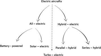
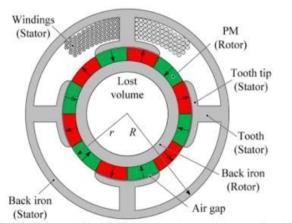
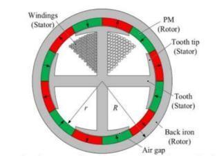
Fig – 4 Schematicoverviewofanoutrunnerbrushless machine
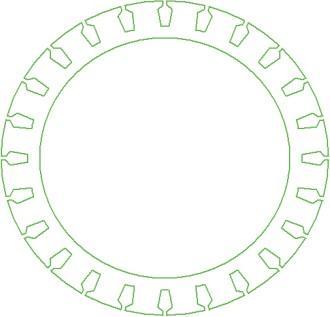
TheoutlineofthemachineisfirstcharacterizedusingAnsoft Rmxprtsubpackage.Themachinehasbeendesignedhere foroptimalvaluesforstator,rotor,permanentmagnets,core material and winding configurations. Since as per the requirement, the power required for 2200 rpm of the machine is about 12kW, the current density should be sufficiently high inside the slot windings for the expected poweroutput.Thecurrentdensityandelectricalloadingon themachinecanbeincreasedbyincreasingthenumberof turns and armature current in the slot windings or alternatively,byreducingtheslotsizeandincreasingtheno. ofSlotsinstator.Sinceincreasingtheno.ofturnsincreases the excitation current required, the slot size has been optimized for an acceptable input phase current value as shown in the relation. The Figure 5.2 shows the selected statorconfigurationwithgivendimensions.
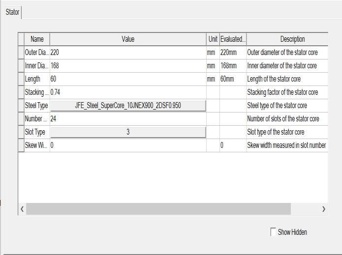
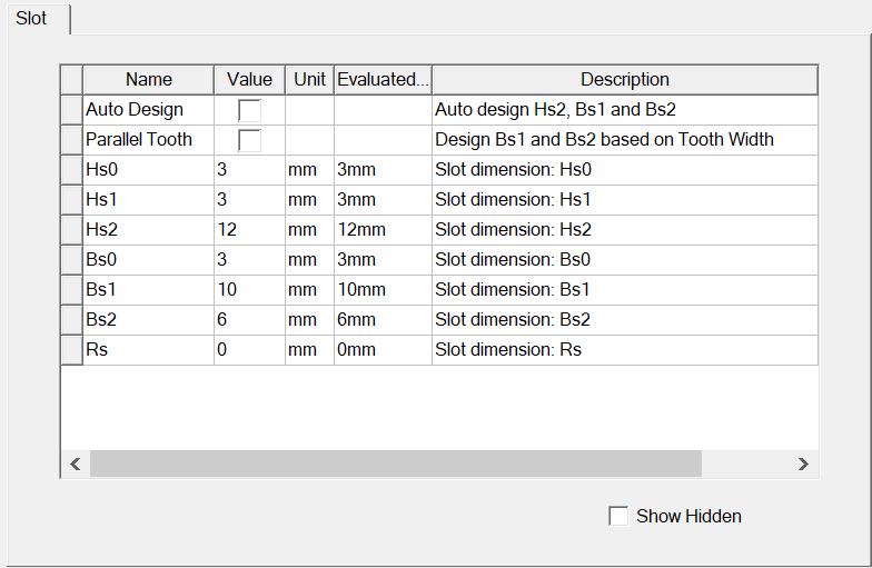
Fig 5 - Statorconfiguration
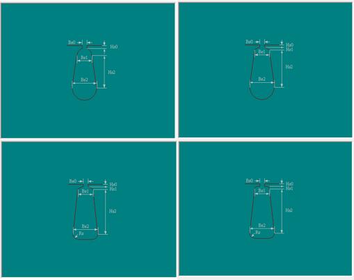
Fig – 6 : DifferenttypesofSlots
Stator has been subjected to dual layer whole coiled type winding with respect to available stator slot area. The automaticdesignoption by thesoftwarehasbeenutilized forcreatingthenumberofstrandsandconductorsperthe slottobeusedfordesign.Sincethedesignhas20polesand 24 slot counts, unit coil pitch has been selected. The final windingconfigurationusedforthemachinewasdescribedin belowfigure.
Fig -5:Statorconfiguration
International Research Journal of Engineering and Technology (IRJET) e-ISSN:2395-0056
Volume: 09 Issue: 11 | Nov 2022 www.irjet.net p-ISSN:2395-0072
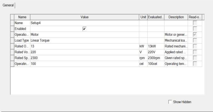
In reference with the of wind conditions available for an aircraftduringtheflight,pilothavetocontrolthepropulsion systemwithrespecttothosewindconditions.Inaconstant poweroutputmachine,themachinerunsatconstantpower irrespectiveoftheloadactingonthemachine,whereasina constant speed output machine, the machine runs at a constant speed irrespective of the load acting. With reference to first case if the load acting is higher than the torque available by the machine, the machine fails to operate.Whereasinsecondcase,forthetorqueavailablefor a specific speed,ifloadismore,againthe machinefailsto operate. Hence an aircraft requires a variable torque and speedcontrollablepropulsionsystem,thus,themachineis designedforlineartorqueoutput,wherethetorqueoutput by the machine has linear proportionality with the speed whichiscontrolledbyoperatingsystem.
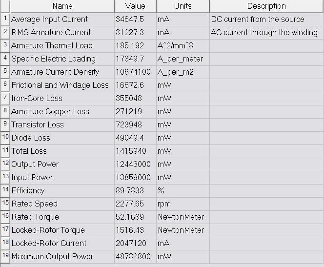
Fig – 6:
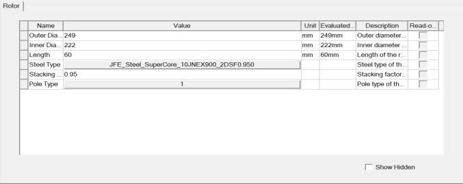
The rotor core material selected was same as the stator laminationmaterial,andhasastackingfactorof0.95.The advantageofexteriorrotormachinesisthattheinertiacan beadjustedbyaddingadditionalmaterialtotherotorasper the application requirement. Since aerospace applications requires the higher torque and speed requirements, the motorinertiawillbeofanimportance.AstheearthMagnets likeNeodymiumIronBoronorSamariumCOBALTMagnets hashigherenergydensitypropertiestheyhavebeenchosen asaprimarypreferencefortheapplication. SinceNdFeBhas lowercurietemperatureandhenceloweroperatingthermal point than the requirement, SmCo28 grade magnets has beenselectedforrotorpolesasdiscussedearlier.
Fig – 8: Solutionsetup
ThefullloadoperationalperformanceoutputbytheRmxprt environmentobtainedasshownbythebelowfigure.
Fig – 7 :Rotorconfiguratio
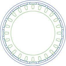
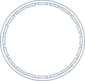
Fig – 9 : Steadystateperformance
International Research Journal of Engineering and Technology (IRJET) e-ISSN:2395-0056
Volume: 09 Issue: 11 | Nov 2022 www.irjet.net p-ISSN:2395-0072
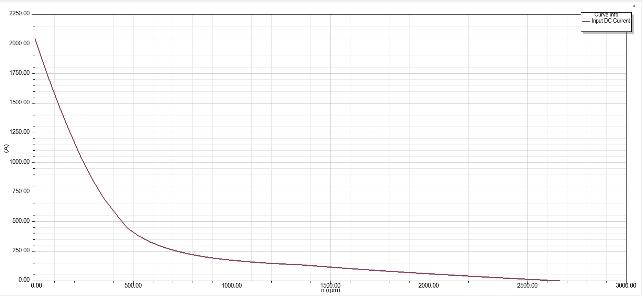
Fig – 10 : InputDCcurrentvsSpeed
Fig – 11 Outputpowervsspeed
The transient analysis indicates the time dependent performanceofthemachine.Herethemachineisanalyzed forfluxdensitydistribution,fluxlinestorqueduringmotion, power with respect to time, etc. The Rmxprt model is imported into Ansys Maxwell 2D environment and FEM analysisisdonebyassigningboundariestothemodel.
Thetransienttorqueanalysisisdoneforfirst6milliseconds. The figure below shows the torque the transient torque characteristicsofdesignedmotor.
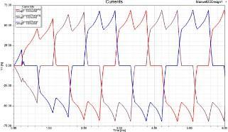
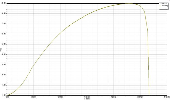
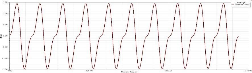
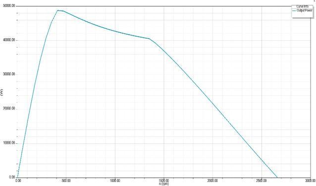
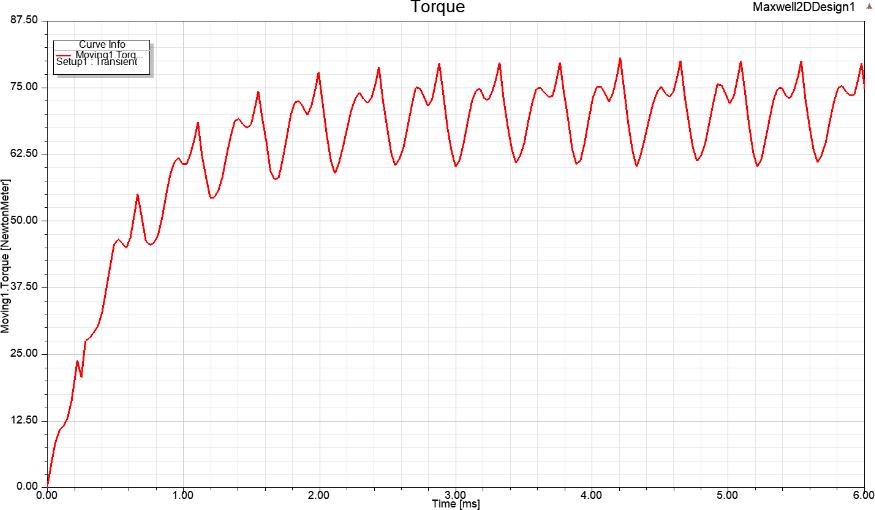
Fig – 13 : Torquewithrespecttotime
The phase current supplied and the variation of each currentwithtimeduringoperationisanalyzedandshown below.
Fig – 14 : Phasecurrentvariation
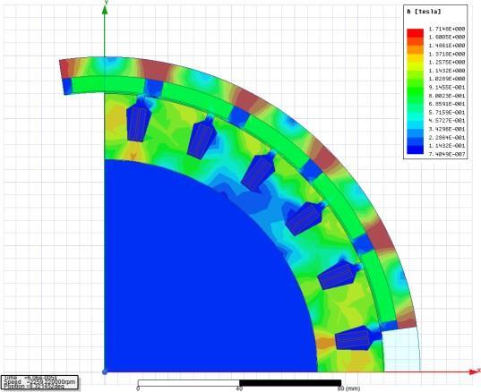
Thesaturationfluxdensityvalueoftheselectedcorematerialis of1.8T.whereasthemaximumoperatingfluxdensityamong the motor parts is obtained as 1.72T. since the maximum fluxdensity among the parts of machine is less than that of saturation flux density, the 1.72T is an acceptable value over1.8T.
Fig – 12 : Coggingtorquebetweentwoteeth
International Research Journal of Engineering and Technology (IRJET) e-ISSN: 2395-0056

Volume: 08 Issue: 08 | Sep 2022 www.irjet.net p-ISSN: 2395-0072
Since the intention is to design a single stage ducted propeller without any guide vanes, the construction of velocity triangles was simple. We know thatinanaxialfan,thereareaxialandswirlcomponentof velocities were present. Since the axial component never changes throughout the rotor stage, the components Cx2 andCx3 remainssameandidentical.
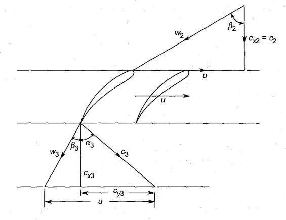
ByEuler’sequation,thestageworkisgivenby, Wst=uCy3
Fig – 15 : Distributionoffluxdensity
For the designed brushless machine, propulsion CFD analysisoftheductedpropellerisconductedinthissection in order to show up the advantages of motor embedded propulsion system over the shaft driven one. The torque requiredforboththecaseswereextractedthroughtheCFD analysis and the final conclusional factors were discussed basedontheresults.
Asimpleductedpropellerwithoutanyguidevanesasshown isdesignedbyusingbladeelementmomenttheoryandstage velocitytriangles. Apythonprogramisdevelopedbasedon thistoobtaintheaccuratefinalresultsofthefandimensions.
Andhencethepowerrequiredtodrivethefanisgivenby, P=muCy3
Wherethemassflowratemcanbeobtainedby, m=ρACx
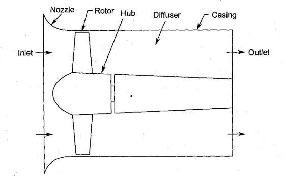
Fig – 16 : Schematicrepresentationofaductedfan
Fig – 17 :
Acomputerprogramisdevelopedinpython3.8interfacein ordertodesignanefficientpropellerbladewithrespectto expected hub diameter. The code uses blade element momentequations,forceequationsandconstraintequations to accurately design any propeller blade for a ducted propeller.
Importing the numpy as np From the scipy.integrate import quad
def initn():
International Research Journal of Engineering and Technology (IRJET) e-ISSN: 2395-0056
Volume: 08 Issue: 08 | Sep 2022 www.irjet.net p-ISSN: 2395-0072
bl0 = [Rh]
b = np.linspace(Rh, R, 5) [bl0.append(b[i]) for i in range(1, len (b))]
r = np.array(bl0) print('\nRadial position ->', bl0)
A = np.pi*((R**2)-(Rh**2))
mdot = rho*A*V u = (np.pi*n/30)*r vt = Preq/(mdot*u)
MomentumEqns(rho, V, r, vt, u)
def MomentumEqns(rho, V, r, vt, u): dltp = rho*vt*(u-(vt/2)) a = vt/(2*u)
T1 = 2*np.pi*r*dltp Qr = 2*np.pi*rho*r*V*vt
ForceEqns(V, u, a, rho, r, vt)
def ForceEqns(V, u, a, rho, r, vt): phi0 = [] K = r*vt BG = 2*np.pi*K phir = np.arctan(V/(u*(1-a))) phi = np.degrees(phir)+3 [phi0.append(phi[i]) for i in range(0, len(phi))]
print('Section blade angle ->', phi0)
L1 = BG*rho*u*(1-a)/np.cos(phir)
Qr1 = L1*np.sin(phir) T11 = L1*np.cos(phir) a = K/(2*r*u)
Constraint(n, V, R, Rh, r, K, a)
Geometry(V, K, u)
def Constraint(n, V, R, Rh, r, K, a): eff0 = [] ndr = r/R ndr0 = Rh/R a0 = a[0]
ohm = (np.pi*n/30)
J11 = lambda ndr: 4*ohm*ndr/(V**2)
I11 = lambda ndr: 4*ohm*ndr*(1+a0)/(V** 2)
I21 = lambda ndr: 4*ndr*ohm*a0/(V**2) J10 = quad(J11, ndr0, 1) I10 = quad(I11, ndr0, 1) I20 = quad(I21, ndr0, 1) J1 = J10[0] I1 = I10[0] I2 = I20[0]
j = V/(2*(n/60)*R) Pc = K*J1 Tc = (K*I1)-((K**2)*I2) T = Tc*(rho*(V**2)*np.pi*(R**2))/2 P = pc*(rho*(V**3)*np.pi*(R**2))/2 eff = (T*V)/P [eff0.append(eff[i]) for i in range(0, len(eff))]
def Geometry(V, K, u): c0 = [] W = np.sqrt((u**2)+(V**2)) Wc = (4*np.pi*K)/(Cl*B) c = Wc/W [c0.append(c[i]) for i in range(0, len( c))] print('Sectional chord ->', c0, '\n')
rho = 1.23 V = 40 n = 2260 Rh = 0.13 R = 0.5 Cl = 0.7 B = 5
Preq = 12000 initn()
Thepropellerwasdesignedbasedontheabovedeveloped program which is oriented with the designed outrunner machine of 12kW. And the designed propeller vane has 92.8%efficiency.Thedesigndimensionalparameterswere listedbelow.
International Research Journal of Engineering and Technology (IRJET) e-ISSN: 2395-0056
Volume: 08 Issue: 08 | Sep 2022 www.irjet.net p-ISSN: 2395-0072
stores energy and generates electricity inside of a sealed enclosure(externally).Byusinga fuel cell,wecanexpand theenergycapacityofasystemanddososimplybyadding morefuelasneeded.
Table - 5 :Propellerdimensions
Solar panels, which can be various sections like wings or surfaces, are nothing more than the composition of solar cellscoupledinacertainorcorrectarrangement(fuselage, tailpartetc.,).Here,duringtheday,theconversionofsolar lightintoelectricalenergydependsontheSun'sirradiance andtheslantofthelightrays.
The converter, also known as the Highest Power Point Tracker,willmakesurethatthesolarpanelsconnectedto the aircraft wing are producing the maximum amount of power. This electricity is first made available to the onboard electronic systems and the propulsion system, after which the battery will be charged using the excess energy(requiredforbackup).
Andsincethesolarpanelsarenolongerproducingpower during the night or when there is insufficient sunshine (dull or gloomy weather), the batteries are then used to powerthevariouscomponentsonboardtheaeroplane.
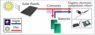
Duringthenight,thefuelcellproduceselectricityandwater by combining the gases of oxygen and hydrogen in a regulatedreaction.Andduringtheday,theelectrolyticcells recharge the system by electrolysis the process of convertingthesamewaterintohydrogenandoxygengases that are then stored under high pressure in tanks in the wingsoftheaircraft toregeneratethesystem.Onadaily basis, these reactants are recycled. Regenerative fuel cells are one name for this kind of technology. Additionally, a novel system design can be created that uses different electrochemicalcellstoproduceelectricityandelectrolyte water,oritcanusethesamecellstoaccomplishbothtasks (ata verysmall sacrificein efficiency).Theothertypeisa unitizedregenerativefuelcell,whichisareversibledevice.
The main scope is to design and developing the low-cost unmanned HYBRID aircraft propulsion (electricsolar) airplanes to carry out science missions like atmosphericstudiesandcommunicationsupport,common ormilitaryobservationandfortheobservationmissions.
Design: CatiaV5isusedtodesignthesolaraircraftengine.
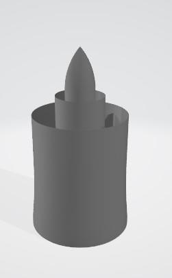
Fig - 18 : WorkingprincipleofSolaraircraftengine.
Sincebothbatteriesandfuelcellsstoreenergyintheformof reactants and generate power through electrochemical processeswithinthecells,thisisnotsurprising.Thefuelcell storesoneorbothofitsreactantsoutside,whereasabattery
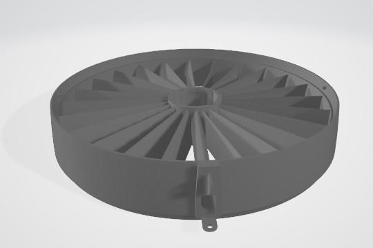
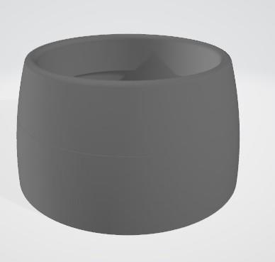
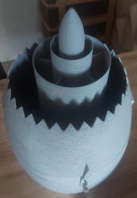
Fig – 19 Engine rear part.
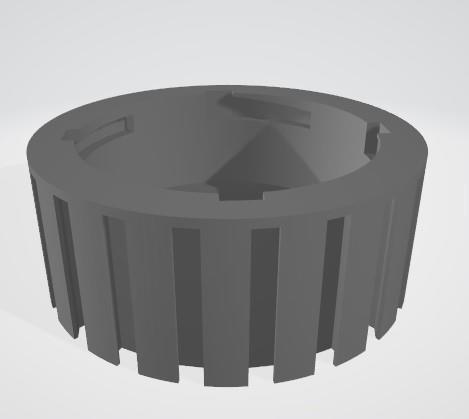
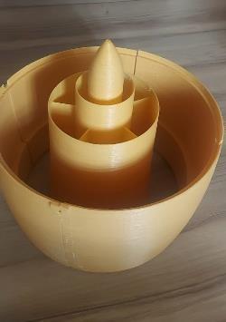
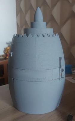
Fig – 20 : Enginemid-sectionpart.
International Research Journal of Engineering and Technology (IRJET) e-ISSN: 2395-0056
Volume: 08 Issue: 08 | Sep 2022 www.irjet.net p-ISSN: 2395-0072
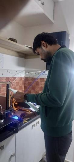
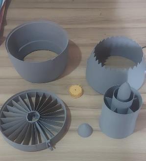
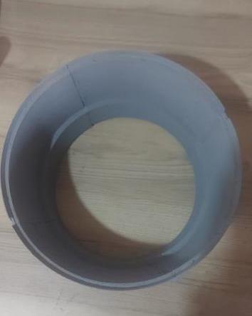
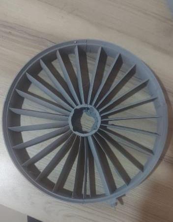
Modellingisdoneusing3DPrintingtechnology. Workinghourswasaround400hours.
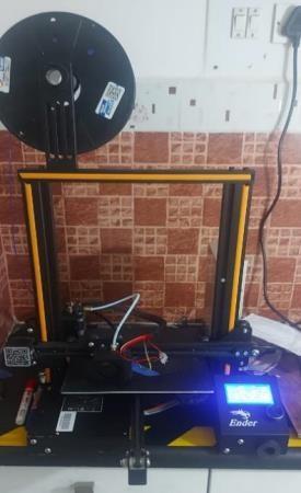
Adigitalfilecanbeusedtocreatethree-dimensionalsolid thingsusingthe3Dprintingtechnique.Anadditiveprocess is used to create a 3D-printed object. In this additive technique,materialislayeredontopofoneanotheruntilthe desiredthingisconstructed.
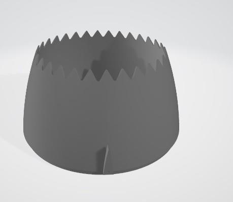
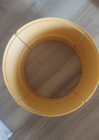
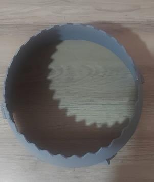
Fig – 21 : : Engineoutercasing.
Fig – 22 : : Nozzlepart.
Fig – 23 : RotorShaft.
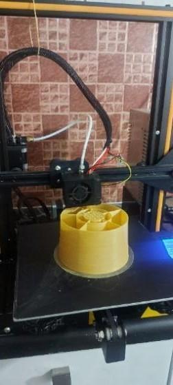
Fig – 24 : 3DPrinter.
Firstly,theCatiafile/designfileisopenedinthesoftware calledUltimakerCura5.0.0

Slicing:thereisanoptioninthesoftwareUltimakerwhich convertstheCatiafile.STLformatintoG-Code.
Slice=ConversiontoGcode Thenthe G-code isopenedin3Dprinterbyconnecting withSDCard.
Thenthefilamentisgiventofeed, © 2022, IRJET | Impact Factor value: 7.529 | ISO 9001:2008 Certified Journal |
International Research Journal of Engineering and Technology (IRJET) e-ISSN: 2395-0056
Volume: 08 Issue: 08 | Sep 2022 www.irjet.net p-ISSN: 2395-0072
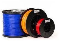
Filament
International Research Journal of Engineering and Technology (IRJET) e-ISSN: 2395-0056
Volume: 08 Issue: 08 | Sep 2022 www.irjet.net p-ISSN: 2395-0072
Fig 33:3DPrintedenginemodelassembly.
Theductedpropellerwithdifferentdrivingconfigurations were computationally analyzed with a specific flow conditiontogetthetorquerequiredindrivingthewholeSys. Thenbyobservingthemotorperformancesrequiredbyboth thedesigns,theconclusionaboutefficientconfigurationis approached.
TheCFDanalysisofthedesignsweredoneinSOLIDWORKS Flow Simulation environment. The flow conditions and propellerdynamiccharacteristicswerekeptidenticalduring analysisforbothdesignconfigurations
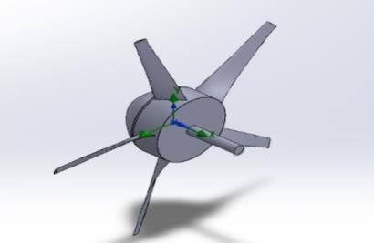
Thepropellerisdesignedwithtwoconfigurations.Oneisto derive the propeller through shaft and another design containsembeddedoutrunnermotor.Thenitisanalyzedfor required torque by driving through shaft and also as embeddedmotorconfiguration.
Fig - 34: Shaftedandshaftlessdesign
International Research Journal of Engineering and Technology (IRJET) e-ISSN: 2395-0056
Volume: 08 Issue: 08 | Sep 2022 www.irjet.net p-ISSN: 2395-0072
The ducted propeller designed was analyzed computationallytoobtaintheaccurate torquerequiredtodrivethewholesystem.
namee Unitts Valuees Progress Criteriaa deltails Use in convergence
GG Maximum totalof Pressure 1 Pa 2315 72.2 4 100 35944 .9006 8470.4 6065 On
GG Force (X)3 N -635. 732 100 1163. 24671 364.38 848 On GG Torque (X)4
N *m -43.0 08 100 5.078 60295 5.0752 943 On GG Torque (Y)5
Fig – 35 :Computationaldomain-Shaftdrivenfan
Thepropellerisanalyzedforaflowlaminarandturbulent flowconditions.Sincethetorquerequireddependsonthe turbulenceofinletflowfield,a higherturbulencefactoris introducedtogetaccuratetorquevalueasshowninbelow table (If the turbulence is higher, the resistive torque requiredforthepropellerisalsohigher).
Turbulence intensity Turbulence length (m)
Angular velocity (rad/sec)
15% 0.8 900
Table- 6 : Freestreamconditions
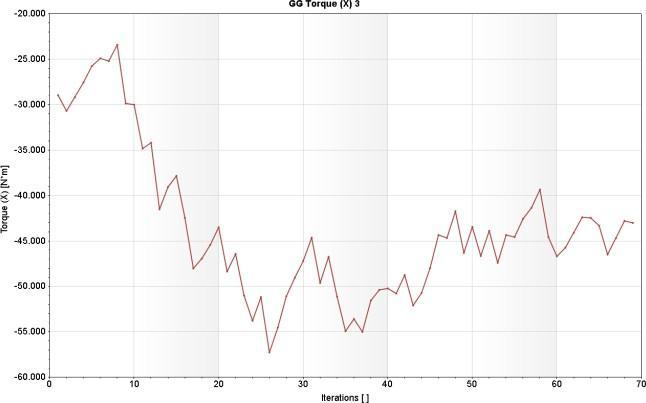
In this case, since the propeller is to be driven through a shaftconnectedtoamotor,anadditionalmassoftheshaft hastobeconsideredinbetweenthepropellerhubandthe rotorof themotor.This increases the inertiaof the whole propeller–shaftsetbutitalsoreducesthecontributionof the inertia with torque since the shaft diameter is less compared to hub diameter and contribution of rotational inertiadependsonthediameterofcomponent.Thebelow table shows the torque required to drive the propeller in mentionedspecificflowcondition.Thistorquerequirement increasesastheshaftdiametergetincreasedduetoincrease involumeandmass.
N *m -28.1 94 100 19.34 02465 10.286 5316 On GG Torque (Z)6
N *m 16.1 13 100 15.43 17377 9.6397 8628 On
Table – 7 : Result-Shaftdrivenpropeller
Fig – 36 : Torquedemand–Shaftedpropeller
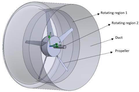
Since there is no shaft present in the motor embedded configuration,theonlyrotatingregionisthepropellerwith ahollowhub.
Fig - 37:Computationaldomain–Shaftlesspropeller
International Research Journal of Engineering and Technology (IRJET) e-ISSN: 2395-0056
Volume: 08 Issue: 08 | Sep 2022 www.irjet.net p-ISSN: 2395-0072
As in the previous shaft driven condition, the flow field conditions were taken identical in order to compare the torquerequirementdemandedbyboththeconditionseasily.
Turbulence intensity Turbulence length (m)
Angular velocity (rad/sec)
15% 08 900
Table – 8 : Freestreamconditions
In this case, since there is no shaft is introduced to drive propeller,onlythemassofhubandrotorcontributesforthe inertia.Alsobecauseoftheabsenceofshaftorgearbox,the massandvolumeofthewholesystemgetreduced.Dueto reduction in this mass and volume, torque required to overcome the inertia is also get reduced. And hence the torque demand by the propeller is lower compared to previousshaftdrivencase.
name Units Values Pro gress Criteria delta Use in convergence
(X)GG Torque
GG Maximum Total Press ure 2
GG Force (X) 4
GG Torque (Y)5
GG Torque (Z)6
N*m -413 69 100 4.240 0954 2
Pa 2295 985 8
100 3338 1.863 2
4.176 60895 On
7870. 62764 On
N 222. 681 100 1410. 3670 5
N*m -4.32 3 100 1710 1270 4
N*m 3.78 6 100 2489 9388 2
366.2 45403 On
7.618 50285 On
9.352 42397 On
Table – 9 : Result-Shaftlesspropeller
At final the difference in the performance and characteristics of both shafted and motor embedded techniques were compared and discussed in this section. Based on the performance comparison, the suitable techniquefordifferentaircraftapplicationswillbediscussed consideringthepreviousresults.
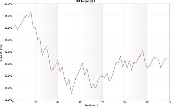
Fig – 38 : Torquedemanded-Shaftlesspropeller
Comparingtopreviouscase,inthiscondition,thepropeller hubisdirectlydrivenbytherotorofoutrunnermotor.When driving a shaft, due to the fact that the shaft diameter is smaller than the propeller hub, the contribution of inertia withtorqueisless.Butwhileconsideringthiscase,sincethe hub is directly driven by rotor by embedding the whole motorinside,thecontributionofinertiaismorefortorque duetolargerdiameterofthehub.
A shafted engine may include some couplers, sometimes gear box or may need specially designed shafts for some drives. This arises a rise in overall volume and hence the weight of the entire propulsion system. Where as in the shaftless,motorembeddedpropulsionsystem,thevolume is reduced, since the propulsion system consist of only a hubpropellerdrivenbyembeddedmotor.
The torque required to drive a propeller during flight is an important factor. This torque requirement is directly depending on inertia of the rotating regions as shownbyequationbelow.
T=Iα
International Research Journal of Engineering and Technology (IRJET) e-ISSN: 2395-0056
Volume: 08 Issue: 08 | Sep 2022 www.irjet.net p-ISSN: 2395-0072
Where‘T’isthetorquerequired,‘I’isthemomentofinertia and ‘α’ is called angular acceleration. Since the shafted propulsion system has more components than a shaftless one, the inertia of the propeller is more. Because of this higher inertia, the torque required to drive the propeller becomesgreatercomparedtoshaftlessone.
Themomentofinertiadependsonthemassanddiameterof therotatingshaftorregion.Illustratively,forasolidrotating dischavingofradiusof‘r’andithastheMass‘M’,thenthe momentofinertiawillbegiven,
I = Mr2
This sets a constraint such that, for a shafted propulsion systemsincetheshafthassomeradialdimensionandmass, thisintroducessomeadditionalinertiatothepropellerhub, whichhastobeovercomebythecertaintorquebymotor.
Observing the results of shafted propeller, the average torquerequiredbythepropellerisof43Nm.Whereasfora motorembeddedshaftlesspropulsion,therequiredtorqueis of41.37Nmforsamefreestreamconditions.Thissaysthat the torque required for a shaftless propulsion system, the torquerequiredissignificantlylesscomparedtoashafted propulsionsystem.Thisisbecausetheshaftintroducesan additionalmomentofinertiawhichhastobeovercomeby thetorquesuppliedbymotor.
The torque is an important factor during flight to resist the variational freestream loads acting on propeller vanestoprovidespecificthrustatgivenrotationalspeedof the propeller. This says that to provide higher resistive torqueforpropeller,inertiaofthepropellershouldbemore so that contribution of inertia in this resistive action is enhanced. At the same time, the weight of the propulsion system should be reduced in order to increase flight performance.
Since the inertia depends on the product of mass andradiusoftherotatingregion,thecontributionofinertia canbeincreasedbyintroducingalargehollowhubrotating region as in the case of shaftless motor embedded propulsion.
When the shafted propulsion is considered, the additional mass of the shaft introduces a lesser contribution of inertia with torque because of the smaller radial dimension of the shaft. This causes a less thrust output for given torque and rotational speed compared to shaftlesspropulsiontechnique.Since,inthe shaftlesstechnique,thehubofthepropellerishollowand theembeddedrotorofthemotor is direct contact with
hub, the radius of the hub is increased. This reduces the torque required and allows the propeller rotational speed to more effectively act upon the incoming freestream thereby increasing the total performance of the entirepropulsion. This can be compared by the results givenbelow.
Velocity(m/s) 27.14 30.791
Total thrust(N) 201918 309542
Thewholestudyisorientedtowardsrealizingthe bestpossiblewaytopropelalightweightandsolarpowered electricaircraft.Theperformedobservationsconcludesthat anoutrunnermotorembeddedpropulsionsystemprovides moreeasepropulsionbyconsideringfollowingaspects.
1. Themotorwithinteriorrotorcanonlydriveapropeller throughashaft,whereasamotorwithexteriorrotorcan beembeddedinsidethehubofapropeller,morelikely in a ducted propeller thereby reducing weight and volumeoftheentirepropulsionsystem.
2. Anexteriorrotormotorcanhavesmallervolumethan aninrunnermotorforsametorqueoutput.Thisreduces sufficient mass of copper windings and core steel materialandhenceopensdoorformoreeasepropulsion techniquesforlightweightelectricaircrafts.
3. Theinertiaofthemotorcanbemaintainedbyaddingor removing the material in the hollow hub of propeller. This allows for capability to design the propulsion systemforarequiredinertialcontribution.
4. Sincethepropellerconsistoflargerhubdiameterwith hollow structure, this helps in higher contribution of inertiatowardsvariablefreestreamloadsduringflight bymaintainingconstantpropellerspeed.
5. Theonlydisadvantageisthattherequiredstartingtime oftheengineduetohigherinertiaofthehub,sincethe inertiaofmountedvanesalsoshouldbeconsidered,the startingtimeoftheenginemaydelay.
6. This delay in staring time of the motor restricts this embeddedmotorconfigurationforhighweightaircrafts. However,thisconfigurationismorelikelysuitablefor solarpropelledaircraftsbecauseofaboveadvantageous characteristicsandthusthisconfigurationisintroduced as‘magnetopropulsivesolarengine’.
International Research Journal of Engineering and Technology (IRJET) e-ISSN: 2395-0056
Volume: 08 Issue: 08 | Sep 2022 www.irjet.net p-ISSN: 2395-0072
1.UniversityofDunaujvaros,"Electricaircraft-presentand future," H-2400 Tancsics-Mihaly-utca 1, Hungary, 2019. AndrasNagy
2.Review of Maglev Train Technologies by Ki-Chan Kim, Hyung-Woo Lee, and Ju Lee was published in the IEEE TransactionsonMagneticsin2006.
3.ElectricalEngineeringDepartment,MaulanaAzadNational InstituteofTechnology(MANIT),Bhopal,India,"Electrical ComponentsofMaglevSystems:EmergingTrends,"article publishedin2019.
4. "DesignandPrototypingMethodsforBrushlessMotors and Motor Control," Shane W. Colton, Department of Mechanical Engineering, Massachusetts Institute of Technology, 2010, partial fulfilment of the requirements forthedegreeofMSinMechanicalEngineering.
5.International Journal of Technical Research and Applications, "Solar Powered Aircraft," Shubham Patil, RajdeepJagdale,PratikThakur,andSar,2016.
6."DesignandPrototypingof3-PhaseBLDCMotor,"byY.B AdyapakaApatya,AriesSubiantoro,andFeriYu,Electrical EngineeringDepartment,UniversitasIndonesia,Indonesia, 2017.
7.Devaiah Nalianda, propulsion Engineering Center, Cranfield University, Bedfordshire, UK, 2016. "Review of ModernLowEmissionsCombustionTechnologiesforAero GasTurbineEngines."
8."Designofanouter-rotorbrushlessdcmotorforcontrol momentgyroscopeapplicationsbyN.Cagan,"MiddleEast Technical University's degree programme in natural and appliedsciences,2015.
9.IET Electric Power Applications, Vols. doi: 10.1049/ietepa.2017.0639,no.13,2018.X.Zhang,"Largeelectrification machinesforaviationelectric,"DepartmentofElectricaland Computer Engineering, University of Illinois, UrbanaChampaign,306N.WrightStreet,Urbana,IL61801,USA
10. Computer-Aided Design of a Brushless DC Motor with Exterior-RotorConfiguration,NationalYunlinUniversityof Science&Technology,Vols 10.3722/cadaps.2012.457-469, no.CADSolutions,LLC(2012),http://www.cadanda.com,p.
11.1994issueofthepropulsionandpowermagazine, "DesigningofOptimumPropellers."
12.Designandanalysisofsingleanddual rotationducted fans, G. S. Page, 34th Aerospace Sciences Meeting and Exhibit, Reno, NV, Jan. 15–18, 1996, Vols. AIAA Meeting PapersonDisc,January1996,no.AIAAinc.,1996.
13.Contra-rotatingDuctedFanAerothermodynamicDesign ProcedureforUnmannedApplications,A.F.Nemnem,Cairo, Egypt: Military Technical College, Aerospace Engineering Department,vol 322309589,no.AIAA,2018.
Mr. Chandrashekar
Presently,P.G.Student, DepartmentofAerospace PropulsionTechnology,VTUCPGSBengaluruRegion,VIAT, Muddenahalli,Chikkaballapura, Karnataka,India
Dr. Chikkanna N
Associate Professor & Chairman, Department of Aerospace PropulsionTechnology,VTU-CPGS Bengaluru Region, VIAT, Muddenahalli, Chikkaballapura, Karnataka,India.
Mr. Sanjeev G Palekar
AssistantProfessor Department of Aerospace PropulsionTechnology,VTU-CPGS, Bengaluru Region, VIAT, Muddenahalli, Chikkaballapura, Karnataka,India.
Mr. Prashanth Radhakrishnan Director–AerospaceR&D DautyaAerospace Bengaluru,Karnataka,India