International Research Journal of Engineering and Technology (IRJET) e-ISSN:2395-0056

Volume: 09 Issue: 11 | Nov 2022 www.irjet.net p-ISSN:2395-0072
International Research Journal of Engineering and Technology (IRJET) e-ISSN:2395-0056
Volume: 09 Issue: 11 | Nov 2022 www.irjet.net p-ISSN:2395-0072
Kumar1 , Amit Kumar2
1Asst. Prof., Department of Mechanical Engineering, Swami Vivekanand Subharti University (U.P), India
2 Asst. Prof., Department of Mechanical Engineering, Swami Vivekanand Subharti University (U.P), India ***
Abstract - To better understand the complex welding processes the automatic and flexible geometry measurement of the weld pool surface can help and can also provide feedback to better control this process. Anadditionalsourceof illumination is used in most of the existing imaging systems to remove the light interference coming from the welding arc. But it is usually costly. This paper introduces a novel low-cost optical-sensor-based monitoring system working under passive mode to monitor the wire + arc additive manufacturing process, particularly for plasma arc welding. Initially, configurations and parameters of the camera are investigated to achieve good visualization of the weld pool.To perform this procedure a new camera calibration method is proposed using the nozzle of a computer numerical control (CNC) machine imaging system, estimating the position of the camera concerning the inspection surface and its orientation in an easy-to-use approach. allows. Verification tests show that the average error of calibration is less than 1 pixel. To measure the width of the bead during the welding process, an image analysis routine is proposed, as a casestudy.Theresults analysis shows that the proposed system is effective to measure the dimension of the weld pool.
Key Words: Additive manufacturing, camera calibration, edge detection, plasma arc welding, wire + arc additive manufacture
ADDITIVE manufacturing is definedasa processof threedimensional printing in which parts are built by adding materialslayerbylayer.Comparedtotraditionalsubtractive manufacturing technologies, this technique allows a high reduction in costs by substantially saving material and reducing lead time. It also offers higher flexibility in the design. Wire + arc additive manufacture (WAAM) uses an electricarcasthepowersourceandwireasthefeedstock, whichisoneofthemostpromisingtechniquesofAMunder development. WAAM is suitable for medium-large scale manufacturingandisbeingwidelyusedinareassuchasthe aerospace industry, particularly where the need for the manufactureoftitaniumpartsisincreasingsignificantlydue toitschemicalcompatibilitywithcomposites.Italsooffersa cleanerworkingenvironment,higherdepositionrates,and lessriskofcontaminationwhencomparedwiththepowderbased system. The dimensions and geometry of the final piece are very much influenced due to fluctuations in parametersandworkingconditionsintheWAAM.Changes
in operating parameters, heat dissipation, interlayer temperature, and quality of the back layer are among the mainfactorsrequiringsignificantinvestigation.Todealwith these, the process needs to be monitored and ideally controlled. An optimistic approach is to use visualization techniques to track the weld pool geometry allowing monitoring of the process or potentially implementing a closed-loopcontrolsystem.Onlyafewresearchworkshave beenreportedinthefieldofAMregardingopticalsensing and corresponding reliable measurement, but several techniqueshavebeenimplementedfortheautomationand enhancementofweldingprocesses.
Theharshconditionslikemeltinganddepositionofthe metal play a challenging task in taking the high-quality images of the weld pool during the WAAM process. Highintensitylightradiationduetothehightemperatureofthe arcinterfereswiththeimageacquisitionprocess.Thispaper proposedtouseahigh-shutter-speedcamerasynchronized withapulsedlaserasanadditionalsourceofilluminationin gas tungsten arc welding. The camera has a filter that is opaquetoallradiationexceptthelaserwavelength,asthe laserismonochromatic,whichhelpsthesystemwork.This greatlyreducestheintensityoftheplasmalightforthelaser lighttobeseen.Onesolutionistouseanarrayoflow-cost semiconductor laser diodes and a suitable bandpass filter matched to the laser wavelength, in place of higher-cost equipment such as camera heads, laser units, and controllers. use has been proposed. Recently, some improved methods of reconstructing 3-D weld pool geometryassistedbylasershavebeendeveloped.Inthese processes, an additional source of light has been used to measurethesizeoftheweldpoolindirectlyratherthanto reduce arc interference. Using a laser with a dot-matrix structured light pattern, to reflect the light into an image plane, the weld pool surface can be used as a specular mirror.Thecamerarecordstheplaneofthelaserdotsbeing reflected,nottheweldpooldirectly.Thesystemattractsless interest for WAAMs operating under an imaging passive modethanforanactivemode.Inthisprocessthearclightis usedtoilluminatethescene;however,accuratecalibration ofthecamerapositionandapreciseselectionofanarrowbandfiltertoreducethearclightisrequiredinthisprocess. Toenhanceandautomatetheweldingprocessesorextract different features from the weld pool for gas metal arc weldingbasedonAM,someresearchworksusingpassive vision have been reported. A method of using a passive visionsystemformonitoringthewiredeviationduringthe WAAMprocessisintroducedinrecentresearch.Inaddition,
International Research Journal of Engineering and Technology (IRJET) e-ISSN:2395-0056
Volume: 09 Issue: 11 | Nov 2022 www.irjet.net p-ISSN:2395-0072
infrared(IR)camerashavebeenusedtomonitortheweld pool; Still, in obtaining high-quality IR images arc interferenceposesamajorproblem.
In terms of the properties to measure using a camera, most of these research works focus on the step height betweensubsequencelayers,thewidthofthebead,andthe height (nozzle to top surface distance). Accurate measurementofthesepropertiesiscriticaltohavingbetter controloftheWAAMprocessbasedontheinputparameters, such as the arc current, the wire feeding rate, the travel speed,etc.Althoughidentificationoftheoptimalproperties tomonitortheweldpoolisnotthescopeofthispaper,acase study using the proposed imaging system to measure the widthoftheweldpoolispresented.
Plasma arc welding has fewer transfer modes than GMAW processes due to the metal wire not being the electrode,henceitisamorestableprocess.Whencompared to other additive layer manufacturing processes it also allows a higher deposition rate and greater effective wall width.Duetotheseadvantages,itisbelievedthatPAWhas greatpotentialandwillattractmoreandmoreinterestinthe future.Plasmaarcweldinghasaverybrightarccomparedto GMAW; this will greatly increase the complexity of image processing.Whenfacingthischallenge,developingareliable and tailored weld pool monitoring system is, therefore, a timely and highly demanded process. To our knowledge, veryfewpassiveimagingsystemshavebeendevelopedfor the plasma arc welding process due to the challenge of lightingconditionsandcalibration.Thispaperintroducesa flexible optical-sensor-based monitoring system without additionallightingsourcestomeasurethegeometryofthe weld pool in the plasma arc welding process. When accommodatingthemeasurementofdifferentproperties,an easy-to-usecalibrationroutineisdevelopedtoconvertthe measurement on an image plane to the world coordinate system.Suchresearchwillbeparticularlyusefulforimaging systemsbasedonasinglecamerathatisrequiredtochange positionregularlytomeasuredifferentpropertiesorbased onmultiplecamerasatdifferentpositions.
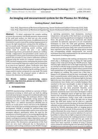
ACNCmachine,aplasmaweldingpowersource,andawire feederarecombinedtoimplementtheplasmaarcwelding processinthisexperiment.
Additionally, the MC500S Weld Vision Camera System, a specialweldingcamera,isusedformonitoringtheprocess.A videocontrollermoduleallowschanginggain,intensity,and shutterspeedtowhichthecameraisconnected.Aswecan observefromfigure1,thecameraismountedonthemoving panelofthiscomputernumericalcontrol(CNC)gantry,with thehelpofanarticulatedarm.Therelativepositionbetween the camera and the torch remains the same during the deposition process because the torch is mounted on the samemovingpaneloftheCNCmachine.Alltheequipment mentioned above issetup insidea chamber.Toavoid the oxidationoftitaniumwhilethedepositionisbeingprocessed the chamber is used to create an atmosphere of inert gas, withargon.Becausethetorchisveryclose(about8mm)to thesubstrateduringtheweldingprocess,whichthecamera willbecalibratedtoward,LEDsusedatthecornerslightwill mostlikelybeblockedbythecomputernumericalcontrol machineandthetorch.Suchasettingwillintroduceshadows inthecalibrationgrid,whichwillmaketheimageprocessing morecomplicated.Anadditionalcablealsomustbesetupin thealreadycrowdedCNCmachine.Whilemeasuringspecific propertiesfromtheimages,thelocationofthecameraplays animportantroleindeterminingthequalityoftheimages. To find out the best configuration of the camera, several experiments were conducted with different camera positions, as illustrated in Fig. 2. The wire can be visible withthehelpoftheleftsetup,butthevisualqualityofthe weldpoolispoorduetoalargeamountofweldingarcand thespecularsurfaceoftheweldpool.Inthemiddleimage,
International Research Journal of Engineering and Technology (IRJET) e-ISSN:2395-0056
Volume: 09 Issue: 11 | Nov 2022 www.irjet.net p-ISSN:2395-0072
the wire can be observed clearly much similar to the previousone,butthevisualizationoftheweldpoolisstill verymuchaffectedbyalargeamountofarclight.Whenwe areobservingintherightsetup,providesthebestviewof theweldpoolwithlessreflection,butinthissetup,wireis not visible. In this experiment mainly focus was on the measurementofthewidthoftheweldpoolonly,sotheright setupwasused.
straightlineandmakesthemcurvyinimages.Thedistortion is caused by the lens. Generally, we can be described distortionbyfiveparameters
{k1k2k3p1p2} ……(2)
wherep1andp2aretangentialparametersandk1,k2,and k3areradialparameters.Thecorrectdistortionmodelscan bewrittenas ………..(3) ………..(4)
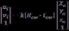
Fig.2.Capturedimageswithdifferentcamerapositions
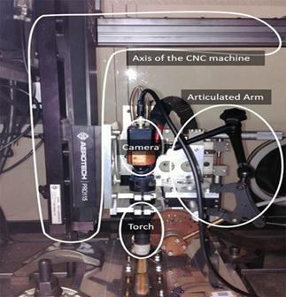
Thecameracalibrationistheprocessofestimatingthe intrinsic and distortion parameters of the imaging sensor andlens,andextrinsicparametersconcerningtheobjectfor measurement.Theseparametersdefinehowapointinthe3Dworldisprojectedintotheimageplane,andtheyarethe keytomeasuringthegeometryofanobject,correctinglens distortions,orfindingthepositionofthecamera.Without consideringdistortion,theequation
……….(1)
mapsany3-Dpointintheworldcoordinatesystemtothe imageplane,where{ui,vi}aretheidealcoordinatesinthe unitofthepixeloftheimageand{ , , }isa3-Dpointin theworldcoordinatesystem.ThesymbolKcorrespondstoa 3×3matrixcontainingtheintrinsicparameters,and[ . ]correspondstoa3×4matrixcontainingtheextrinsic parameters (a rotation matrix and a translation vector), which denotes the transformation from the 3-D world coordinatetothe3-Dcameracoordinate.Equivalently,the extrinsicparametersdefinethepositionofthecameracenter andthecamera’sheadingintheworldcoordinate.
Inphotography,distortionisgenerallyreferredtoasan optical aberration that deforms and bends the physically
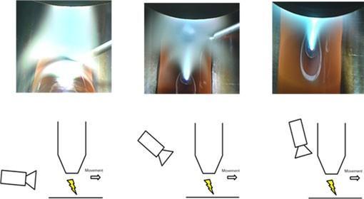
Fig-3.Pinholecameramodelwithintrinsicparameters.
where{ , }arethetruecoordinateintheimagesand theradialdistanceofanidealpixeltothecenteroftheimage isr,expressedas ………(5)
Usually,onlyradialdistortionisconsidered,andtangential parametersaresettozero.
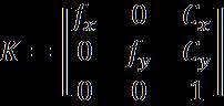
Intrinsicparametersremainconstantoncethecamera and lens is integrated and focused. If the focal length is changed, intrinsic parameters will also change. Intrinsic parametersmodelthepinholecameramodel,whichprojects any3-Dpointfromacoordinatesystemfixedconcerningthe camera into the image plane. The matrix of the intrinsic parameterscanbewrittenas
International Research Journal of Engineering and Technology (IRJET) e-ISSN:2395-0056
Volume: 09 Issue: 11 | Nov 2022 www.irjet.net p-ISSN:2395-0072
………(6)
wherethefocallengthsinthexandydirectionsaredenoted by and respectively.Theyareinpixelsandifassuming square pixels it can be simplified as = = f. and correspondtoanoffsettomovethecenteroftheimageto the upper left corner. Fig. 3 shows these parameters graphically.
The extrinsic parameters consist of a homogeneous transformation,whichincludesarotationandatranslation operation.Thetranslationoperationconsistsofvectorsfrom threedimensions,describedas (7)
Foreachoftheaxis,a rotationoperationhas3-degreesof freedomcorresponding tothreeanglesof rotation,one or each of the axis. In The Euler angles are employed to describearotationoperation,inthisexperimentwhichcan bewrittenas …………(8) where corresponds to a rotation of θ degree aroundthey-axis, correspondstoarotationofφ degreearoundthez-axis,and correspondstoa rotationofψdegreearoundthex-axis.Then,equation(8) canberewrittenas ….(9)

Notethattheextrinsicparametersdependonthelocationof the camera. Any movement of the camera will require recalculationoftheseparameters.
The proposed calibration method requires taking multiplephotographsofthecalibrationpatternfrommore thanoneperspectivetoimproveaccuracy.Inthispaper,a checkerboard,whichisawell-acceptedcalibrationpatternin manyresearches,hasbeenused.Ifthesizeofthechessboard square is determined, the 3-D world coordinates of the
points on the grid can also be estimated, using the world coordinatesystemonit.Thecalibrationprocessconsistsof solvingasystemofequationstofindtheintrinsic,distortion, andextrinsicparameters,whicharetheonesthatrelateany 3-D world point with a pixel position on the image plane. Hence, by knowing the 3-D world coordinate of the checkerboard points and knowing the 2-D pixel position correspondingtoeachofthesepoints,asystemofequations canbesolvedtofindallthenecessaryparameters.Notethat theoretically only one pair of 3-D–2-D points would be needed for each parameter, but as aforementioned increasingthenumberofpointstheerrorcanbereducedby averagingtheresults.
Generally,duringcalibratingonacamera,theprocedure is simply moving a calibration pattern in front of a fixed camera. During this process, some problems arose when tryingthisapproach
1) Thecalibrationpatternmustbeverysmall(15mm ×10.5mm)becausethecamerahasanarrowfield ofview.Itmakesdifficulttomovethepatternonly withsmallhandshaking.
2) TherearemanyelementssuchastheCNCmachine, thetorch,orthechamberitselfthatwouldlimitthe movementofthecalibrationgrid,oncethecamera isfixed.
3) The fact is that all equipment inside a chamber leadstoalackoflight.Ifthegridismoved,alampto illuminateitmustbemovedtoo,duetowhichthis processbecameverycomplicated.
Inthispaper,thecamerawillbemovedwithrespectto thecalibrationpattern,whichwillremainfixed,toovercome these problems, instead of moving the calibration pattern concerningthecamera.Eventhoughsucharoutinehasbeen generally used in the calibration of many applications, its application is new in plasma arc welding monitoring. Furthermore, to estimate the camera’s position, the proposed methodology uses the position of the nozzle concerningtheworldorigin,whichcanbeobtainedbyusing the position of the nozzle displayed by the CNC machine interface. It is noted that the problems listed in the above threemainpoints,sometimesdonotapplybecauseinternal camera calibration usuallydoes not need to beconducted online.
International Research Journal of Engineering and Technology (IRJET) e-ISSN:2395-0056
Volume: 09 Issue: 11 | Nov 2022 www.irjet.net p-ISSN:2395-0072
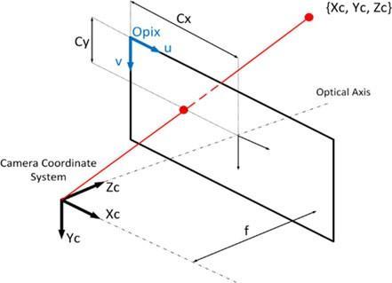
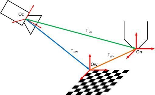
Fig.4.Thecoordinatesystemsrepresentationand transformationsinvolvedinmeasuringthecamerapose.
Ifexceptforadjustingthelens,itisanofflinestepthatdoes not depend on the surrounding equipment. The proposed calibrationroutinecanbesummarizedasfollows.
1) Toplacethecalibrationgridontheplanewherethe depositionprocesswillbeundertaken.
2) Calculate the position of the world origin in the ComputerNumericalControl(CNC)coordinate.
3) Focusthecameraconsideringitslocation.
4) Move the camera to capture pictures of the calibrationgridfromdifferentanglesofview.While moving the camera, the difference between two consecutive pictures should be noticeable. It is suggestedtotakepictureswhenthegrid'srowlines and column lines are not parallel in the image. A picturetakenfromexactlythetopofthegrid,where thelinesareparallel,willcontainlessinformation.
5) Estimatetheintrinsicanddistortioncoefficientsby usingthecapturedpicturesinstep4.
6) Fixthecameratothepositionwheretherecording oftheprocesswillbeconducted,takeapictureof the calibration pattern and record the position of theCNCmachine.
7) Estimate the extrinsic parameters by using the capturedpictureinstep6.
Thelocationofthecameradeterminesthequality oftheimagesreceived.Theproposedimagingsystem alsoallowsautomaticlocalizationofthecamera.The positionofthecameraforthenozzlewillnotchange,asthe cameraismountedwithanarticulatedarmmountedonthe moving system. Since the calibration grid can be fixed whereverconvenient,thepositionofthecamerashouldbe calculated for a point on the moving elements of the CNC machine. The solution to this system is to use an
intermediatecoordinatesystematthenozzle.Thisfig.4that the external parameters obtained in step 7 of the blue change calibration routine compose these. It acts as a rotation and translation transformation to convert the cameracoordinatesystemtotheworldcoordinatesystem. Orange Transformation The task of converting the world coordinatesystemtothenozzlecoordinatesystemisdone bytheorangetransformation.Toestimatethiscanbedone bycomputingthedifferencebetweenthepositionoftheCNC machine in the world origin and the position of the CNC machinerecordedinstep 6. Notethatthistransformation willonlyinvolveatranslationbetweenthetwocoordinate systems,butwillnotinvolveanyrotation.
Weknowthebluetransformationmatrix (10)
andtheorangetransformationmatrix ……..(11)
thegreentransformationmatrix …….(12)
whichcorrespondstothelocationofthenozzlewithrespect tothecamera,canbeestimatedby …….. (13)
The homogeneous transformation is 4 × 4 matrices composed of a 3 × 3 rotation matrix, a 3 × 1 translation vector,andthescalingfactor.
Once the nozzle position in the camera coordinate (green transformation)isestimated,thelaststepistoinvert this transformationtoobtainthecamera'spositionwithrespect to the nozzle coordinate system. Note that the camera coordinatesofthesystemarealwaysdefinedwiththez-axis pointingtothedirectioninwhichthecameraisrecording. Toreducecomputationaltime,withoutinvertingthe4× 4 transformation matrix, the camera rotation matrix and translation vector can be calculated based on the green transformationdescribedby(14)and(15),respectively, (14) · (15)
International Research Journal of Engineering and Technology (IRJET) e-ISSN:2395-0056
Volume: 09 Issue: 11 | Nov 2022 www.irjet.net p-ISSN:2395-0072
Themajorproblemthatoccursduringtraducingthe measurefrompixelstoreal-worldunitsisthatthereisaloss ofinformation,particularlythedepthwhentakingapicture and projecting the 3-D coordinates of an object into the imageplane(2-D).Foreverypixelintheimage,thereisan infinite number of possible locations in the 3-D space. To measuredistancesandanglesontheimages,recoveringthis lostinformationisessential.
Toaddressthese types ofproblems stereovision isa well-known technique. It uses the principle of having the sametwopointsinbothimages,andthereforefindingthe intersectionofthetwo-pixelraysthe3-Ddepthinformation canberecovered.Inthepresentcase,thistechniqueisnot possiblebecauseonlyasinglecameraisused.Hence,some extra geometrical information is needed to find the 3-D coordinatefroma2-Dpixel. Theplaneequationinwhichwe know the desired pixel will be contained, the extra information that can be used. For instance, the plane that contains the two edges of the bead is a plain in which the welding is taking place during the measuring of the bead width.
Thevectorequationofalinecanbeexpressedas …….(16)
where isapointontheline,and isthelinedirection. Thismeans wouldcontainanypointonthelinebyvarying thedistanceλ∈(−∞,+∞)from tothispoint.Tofindthe vectorequationofthepixelraylineinnozzlecoordinates, canbecalculatedasthecamera position,foundinthe previoussectionexpressedas …(17)
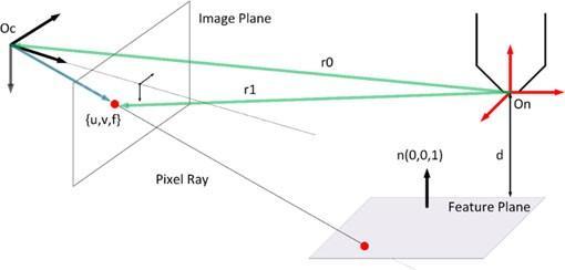
Tocalculatethedirectionvector ,thepoint shown in Fig. 6 can be used. Note that this point in the camera coordinatesystemcorrespondsto ………(18)
Fig-5.Pixelrayprojectionintothefeatureplanetorecover 3-Dinformation
Totransform fromthecameracoordinatesystemto the nozzle coordinate system, the rotation matrix and translationvectorisused.Thetransformcanbewrittenas + (19) Hence,thedirectionvectorcanbecalculatedby = =( + ) - = (20)
Fig-6.Differentpicturesfromdifferentcamerapositionsof thecalibrationpattern.
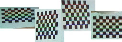
Fig.5showsthisconceptindetail.Toprojectthepixel intothefeatureplaneandrecoverthe3-Dcoordinate,the intersectionbetweenthepixelraylineandtheplanemustbe found. By using the intrinsic and extrinsic parameters obtained previously with the camera calibration the equationofthepixelprojectionlinecanbesolved.
Next,oncethepixelraylineequation,thatdefinesallthe possible 3-D positions of the 2-D pixel, is determined, the intersection with the feature plane is used to recover the exactlocationamongalltheinfinitepossibilities.Havinga generalnormalizedplane (21) where is a unit vector normal to the plane and d is the minimumdistancefromtheplanetotheorigin.Substituting
International Research Journal of Engineering and Technology (IRJET) e-ISSN:2395-0056
Volume: 09 Issue: 11 | Nov 2022 www.irjet.net p-ISSN:2395-0072
(16)into(21),theline-planeintersectioncanbefound;the valueofλcanbecalculatedby (22)
Thissectioncorrespondstosteps4and5ofthecamera calibration methodology explained in Section III-B. to estimatetheintrinsicanddistortioncoefficients,therearea total of 12 positions of the camera have been tested. The resolutionoftheimageis800×600pixels.Fourexamples areshowninFig.6thatillustratethedetectfeaturepointson thecalibrationcheckerboardtoperformthecalibration.Itis tobenotedthattheworldoriginwouldcorrespondtothe firstredpointfromthetopleft.Then,theaxiswillbedefined dependingonhowthesuccessivepointsaredefinedinthe3Dspace.Becausethecalibrationparameterswerecalculated byaveragingtheresultsfromdifferentcalibrationimages, more calibration images usually produce more accurate results. The Visual Studio C++ 2015 and OpenCV library implemented all calibration steps and image processing algorithms.
Assuming square pixels, the detected intrinsic parameters(unit:pixel)are: ……..(23)
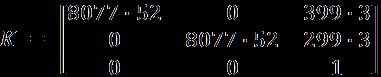
Basedonthematrixshownabovewecanconcludethat = =8077.52pixelsandtheupperleftcornerwithrespectto thecenteroftheimageis =399.3pixelsand =299.3 pixels.
Thedetectedcameradistortionparametersare =2.93 =1755.7 =5.30 ……………. (24)
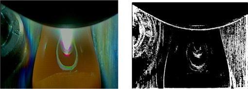
To the raw images we can apply (3) and (4) based on the identified parameters shown in (24) to reduce distortion, whichmeansthatthereliabilityofthemeasurementscanbe improved in the next steps. The right picture of Figure 7 shows a difference image between a raw image and the corresponding undistorted image in binary form. One can notice a clear variation at the boundary of the weld pool, whichwillaffectthefollowingmeasurements
The position of the camera was fixed on the working place after the intrinsic parameters and distortion parametersarecalculated,andonepictureofthegridwas takentocalculatetheextrinsicparameters,asstatedinsteps 6and7inSectionIII-B.
TofindtheorangetransformationinFig.4.Fig.7showsa picturecapturedfromthetopposition,thepositionofthe nozzle of the CNC machine has been used where the coordinatesofthenozzle(unit:mm)are (25)
Knowing that the position of the CNC in the world coordinate(inmm)canbeconvertedto
…………(26) thetranslationvectorfromtheworldcoordinatesystem to the nozzle coordinate system (the orange transformation) (in mm) can be calculated by …………(27)
Theextrinsicparameters,composedoftherotationand translation from the camera coordinate to the world coordinate(thebluetransformationinFig.4),areshown in(28)and(29),respectively
………..(28)

International Research Journal of Engineering and Technology (IRJET) e-ISSN:2395-0056
Volume: 09 Issue: 11 | Nov 2022 www.irjet.net p-ISSN:2395-0072
(29)
Sincethenozzledoesnotrotateconcerningtheworld coordinate system, finally, the camera rotation and translation,concerningthenozzlecoordinatesystem,canbe foundin(30)and(31),respectively ………..(30) ………..(31)
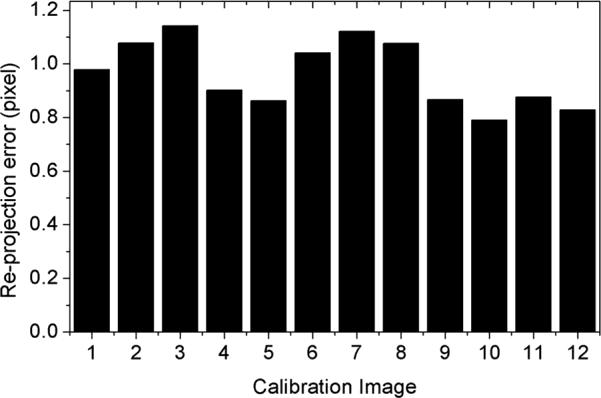
theimage.The12testswithdifferentpositionsofthecamera havebeenconductedtoestimatetheextrinsicparameters. Fig. 8 shows the plot of the reprojection error for every calibration image. In a relatively small range Variation of errorhasbeenobserved.Theaverageerroris0.964±0.124 pixels. Note the camera positions for the 12 cases are different,whichindicatesthattheextrinsicparametersare differentandthescalesbetweentheworldcoordinateand theimagecoordinatearedifferent.Theerrorinmmwould only be valid for a particular case; consequently, it is believed that providing the reprojection error in pixels is moregeneralbecauseitisindependentofthescale/distance oftheobjectthatisbeingrecorded.
The proposed imaging and calibration system aims to accommodatethemeasurementofdifferentpropertiesofthe weldpool.Thissectionpresentsacasestudytomeasurethe widthofthebeadtodemonstratethissystem.
Thefollowingtwoassumptionsaremadetoobtaingood resultsusingthisprocedure.
1) The edgeof the welding beadcanbefoundinthe images.
2) Thedesiredboundarymovementfromoneframeto anotherissmooth.Thisassumptionisvalidformost cases because the change in width of the welding beadwillhardlybeabrupt.
Thestepstomeasurethebeadwidthcanbedescribedas follows:
1) Thedistortionparametersareappliedasshownin (17)tocorrectthedistortion.
Fig-8.Reprojectionerrorforeachimageusedincalibration.

Therotationmatrixin(30)canalsobewrittenasEuler angles,asshownin(32)and(33) =19.10◦ =2.53◦ = 0.77◦ ……….(32) = 160.87◦ =177.42◦ = 179.20◦ ……….(33)
Thereprojectionerrorsofthecalibrationprocessare usedtoevaluatetheaccuracyofthecalibration.Itconsistsof projectingthe3-Dcalibrationgridpointsusingtheestimated calibrationparametersandthenmeasuringthemeansquare errorbetweentheprojectedpointsandtheoriginalpointsin
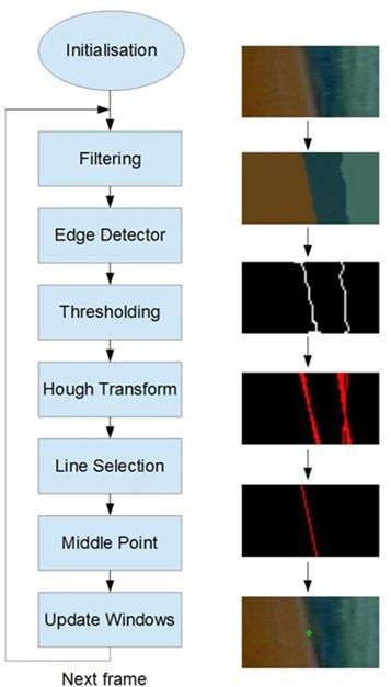
2) Initializeedgepointsandapplyawindow:Toknow wheretostarttrackingtheedgesofthebead,two edge points are initialized. These points are initializedmanuallybyclickingontheimage.Thex andycoordinatesofthefirstpointaswellastheycoordinate of the second point determines by the first click. The second click determines the x coordinate of the second point. Based on these points,twowindowsareapplied,oneforeachofthe edges,toreducetheregionofinterestallowingto reduce the number of calculations to process the imageandfindtheedges.
3) Imageenhancement: Toreducenoise,increasethe chancetofindtheedge,andimprovethereliability ofmeasurement,themeanshiftfilterisapplied.The mean shift of the filter is an iterative filter, which produces a color segmentation of the image by processingacertainamountofneighborpixelswith acertainrangeinthecoloracceptancetomakeone particularcolorregiongrowprogressively.
International Research Journal of Engineering and Technology (IRJET) e-ISSN:2395-0056
Volume: 09 Issue: 11 | Nov 2022 www.irjet.net p-ISSN:2395-0072
4) Edgedetection: Tofindreliableedgesinanimage, theCannyedgedetectorisused.
5) Thresholding: In this paper, Otsu’s thresholding method is employed to remove weak edges and preservethestrongones.
6) Lineextraction:TheHoughTransformtechniqueis employedtofindlinesinabinaryimage.
7) Lineselection:Afterobtaininga rangeofpossible linesfromtheHoughTransform,adecisionhasto be made to select which of the extracted lines correspondstotheboundaryofthebead.Because thepresenceofnoiseintheimageintroducesfalse edges, this step is very essential, which must be filteredbeforethelandmarkdetection.Toaddress this, several assumptions are made, which are as follows:
a) only the most reliable ones given by the Hough Transformwillbeanalysed;
b) the most reliable line will always be the one with the middle point closer to the previous bead corner if this distance is insideacertainthreshold;and
c) If the lines obtained are outside the threshold,themostreliablelinewilltend tobetheoneinsidetheweldpool&thatis attherightsidefortheleftedge,andatthe leftsidefortherightedge.
8) Landmark detection: The middle point on the selected lines will be used as a landmark to calculatethewidth.
9) Calculatethewidthintheunitof“mm”byapplying the extrinsic parameters shown in (23) and (24) identifiedfromthecalibrationprocedure.
Fig.9illustratestheroutineproceduretomeasurethe beadwidthandtheintermediateimagescorrespondingto eachstep.
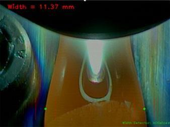
Fig.10plotstheresultsofbeadwidthmeasurementfor the40consecutiveframesfromtwotestsusingtheproposed calibrationsystemandimageanalysismethod,plottedbythe solidcurves Fig.11showsasnapshotoftheweldingbead widthmeasurement.
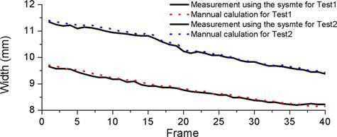
Fig-9.Illustrationofthedevelopedwidthtrackingmethod.
Fig-10.Widthmeasurementfor40consecutiveframesfrom twotests
Fig-11.Widthmeasurementsfortest1atframe1.
International Research Journal of Engineering and Technology (IRJET) e-ISSN:2395-0056
Volume: 09 Issue: 11 | Nov 2022 www.irjet.net p-ISSN:2395-0072
Toevaluatetheaccuracyofmeasurement,thewidthofthe beadwasmanuallymeasuredbasedonthesampledimages andtheresultsareplottedbythedottedcurvesinFig.10. A verygoodapproximationof thegroundtruthindicates by thevisualinspection.TheaverageerrorsforTests1and2 are0.052±0.030mmand0.062±0.034mm,respectively, or1.48±1.82and2.40±1.35pixels,respectively.
Althoughthiscasestudyfocusesononeparameteronly, the proposed imaging system can measure multiple parameters at the same time. For example, if the setup showninFig.2(b)isused,boththewidthofthebeadandthe position of the wire (e.g., the angle of the wire) can be measured.Thiscasestudyonlydemonstrateshowtousethe said system to measure a parameter. To measure other parameters such a methodology can be easily extended, while the difference would be the feature detection using imageprocessingmethods.
The main goal of this research was to investigate how to sense a PAW process through a low-cost computer vision techniqueinaneasy-to-useapproach.Toachievethisgoal, this paper proposed a passive imaging system, which includesadataacquisitionsetup,anovelcalibrationroutine, featureextraction,andmeasurement.Thissystemallowsthe user to track the weld pool geometry online during the welding processing, which can be feedbacked to the controllerofexperimentalparameterstobettercontrolthis process.Theverificationtestsshowedthattheaverageerror ofcalibrationislessthan1pixel.Acasestudytotrackthe beadwidthwaspresentedinthispapertodemonstratehow the proposed system measures the geometry of the weld pool. A novel routine of feature extraction using an image processingtechniquewasproposed.Theresultsshowedthat theproposedsystemcaneffectivelytrackthedynamicsof thebeadwidth.
The main novelty of the research was the calibration methodology, specifically for PAW, which allows transformingmeasurementsfrompixeltothereal-wordunit automaticallythroughaneasy-to-useroutineandaccurately through compensating camera distortion. The proposed calibration moves the camera concerning the calibration pattern on the deposition position instead of moving the calibration pattern due to the space limitation in the CNC machine.Becausethepositionofthecameraconcerningthe nozzlewasalwaysthesame,thepositionofthenozzleand the estimated parameters were then used to localize the camera position. The standard calibration process was tailored to better fit the monitoring of the Plasma Arc Welding(PAW)processthroughsuchuniquechanges.
The proposed system features the following key advantages:
1) Thecameradistortionwasconsideredtoimprove themeasurementaccuracy.
2) Havingthewholecameramodelallowsthefastand accuratecalculationofthecamerapositionin3-D. This can be especially useful to set up the experimental condition and to perform further experiments by changing the camera positions to improve the image quality or to measure other featuresoftheprocess.
3) Nolaserilluminationwasrequired,andthewhole imagingsystemwasrelativelylessexperience.
The proposed calibration process assumes that the camerahassquarepixels( = ,)whichfitsmostcameras. Ifthepixelswerenotexactlysquare,theprocesstoestimate intrinsicparameterswillnotbeaffected&twoindependent parameters and willbeestimated.However,thecurrent equations(18)-(20)willbeaffectedandneedtobeextended, whichwillbeoneofthefutureworks.
Thissystemisreadytoaccommodatethemeasurement of different features either by changing the camera or cameraposition.Futuresworkswillfocusonthefollowing:
1) Identifyingtheoptimalcamerapositiontomeasure multipleimportantparametersoftheweldpool;
2) 3-Dimensionalsurfacereconstructionofthewhole weldpool;and
3) Theinfluenceofdifferentcontrolparametersonthe geometryoftheweldpool.
[1] L. O. Vilarinho, B. Lucas, and M. Houghton, “Dedicated near-infrared vision system for monitoring welding processes,” in Proc. 20th Int. Congr. Mech. Eng., Gramado, Brazil,2009,pp.7–13.
[2] H. Song and Y. Zhang, “Measurement and analysis of three-dimensional specular gas tungsten arc weld pool surface,”Weld.J.,vol.87,pp.85–95,2008.
[3] Z. Wang, “An imaging and measurement system for robustreconstructionofweldpoolduringarcwelding,”IEEE Trans. Ind. Electron., vol. 62, no. 8, pp. 5109–5118, Aug. 2015.
[4] J. Zeshi, L. Haichao, J. Guoquing, and G. Hongming, “Dynamic non-linear modeling of 3D weld pool surface in GTAW,” Robot. Comput.-Integr. Manuf., vol. 39, pp. 1–8, 2016.
International Research Journal of Engineering and Technology (IRJET) e-ISSN:2395-0056 Volume: 09 Issue: 11 | Nov 2022 www.irjet.net p-ISSN:2395-0072
[5]W.Lucas,D.Bertasco,G.Melton,J.Smith,andC.Balfour, “Real-timevision-basedcontrolofweldpoolsize,”Weld.Int., vol.26,no.4,pp.243–250,2012.
[6] C. Wu, J. Gao, X. Liu, and Y. Zhao, “Vision-based measurementofweldpoolconstant-currentgastungstenarc welding,”Proc.Inst.Mech.Eng.,J.Eng.Manuf.,vol.217,pp. 879–882,2003.
[7] J. Liu, Z. Fan, S. I. Olsen, K. H. Christensen, and J. K. Kristensen,“Areal-timepassivevisionsystemforroboticarc welding,”inProc.IEEEInt.Conf.Autom.Sci.Eng.,2015,pp. 389–394.
[8]X.Z.Chen,Y.M.Huang,andS.B.Chen,“Modelanalysis andexperimentaltechniqueoncomputingaccuracyofseam spatial position information based on stereo vision for weldingrobot,”Ind.Robot,Int.J.,vol.39,no.4,pp.349–356, 2012
[9]J.Xiong,G.Zhang,Z.Qiu,andY.Li,“Visionsensingand beadwidthcontrolofsingle-beadmulti-layerpart:Material andenergysavinginGMAW-basedrapidmanufacturing,”J. CleanerProd.,vol.41,pp.82–88,2012.
[10]J.XiongandG.Zhang,“Adaptivecontrolofdeposited height in GMAWbased layer additive manufacturing,” J. Mater.Process.Technol.,vol.214,pp.962–968,2013.
[11] J. Xiong and G. Zhang, “Online measurement of bead geometry in GMAW-based additive manufacturing using passivevision,”Meas.Sci.Technol.,vol.24,no.11,2013,Art. no.115103.
[12] S. W. Williams, F. Martina, A. C. Addison, J. Ding, G. Pardal, and P. Colegrove, “Wire + arc additive manufacturing,”Mater.Sci.Technol.,vol.32,no.7,pp.641–647,2016.
[13]R.Kovacevic,Y.Zhang,andL.Li,“Monitoringofweld joint penetration based on weld pool geometrical appearance,”Weld.J.,vol.38,pp.317–329,1996.
[14] Q. Zhan, Y. Liang, J. Ding, and S. Williams, “A wire deflectiondetectionmethodbasedonimageprocessingin wire + arc additive manufacturing,” Int. J. Adv. Manuf. Technol.,vol.89,pp.755–763,2017.
[15]P.Ghantyetal.,“Artificialneuralnetworkapproachfor estimatingweldbeadwidthanddepthofpenetrationfrom infrared thermal image of weld pool,” Sci. Technol. Weld. Joining,vol.13,no.4,pp.395–401,2016.
[16]Z.ChenandX.Gao,“Detectionofweldpoolwidthusing infraredimagingduringhigh-powerfiberlaserweldingof type 304 austenitic stainless steel,” Int. J. Adv. Manuf. Technol.,vol.74,no.9,pp.1247–1254,2014.
[17] F. Bonnacorso, L. Cantelli, and G. Muscato, “An arc weldingrobotcontrolforashapedmetaldepositionplant: Modularsoftwareinterface andsensors,”IEEE Trans. Ind. Electron.,vol.58,no.8,pp.3126–3132,Aug.2011.
[18]J.Xiong,Z.Yin,andW.Zhang,“Closed-loopcontrolof variable layer width for thin-walled parts in wire and arc additivemanufacturing,”J.Mater.Process.Technol.,vol.233, pp.100–106,2016.
[19]F.Martina,J.Mehnen,S.Williams,P.Colegrove,andF. Wang,“Investigationofthebenefitsofplasmadepositionfor the additive layer manufacture of Ti–6Al–4V,” J. Mater. Process.Technol.,vol.212,pp.1377–1386,2012
Sandeep Kumar (Asst. Prof.), Department of Mechanical Engineering, Subharti University Meerut,M.Tech(Prod.),India.


Amit Kumar (Asst. Prof.), Department of Mechanical Engineering, Subharti University Meerut, M.Tech (Automobile Engg.)NITWarangalA.P.,India
Factor value: